Abstract
In the process of exploring the field of circuits, obtaining the exact solution of the equivalent resistance between two nodes in a resistor network has become an important problem. This paper aims to introduce Chebyshev polynomial of the second kind to improve the equivalent resistance formula of  rectangular resistor network, thereby improving the calculation efficiency. Additionally, the discrete sine transform of the first kind (DST-I) is utilized to solve the modeling equation. Under the condition of applying the new equivalent resistance formula, several equivalent resistance formulas with different parameters are given, and three-dimensional views are used to illustrate them. Six comparison tables are provided to showcase the advantages of the improved explicit formula in terms of computational efficiency, as well as the relationship between resistivity and the maximum size of the resistor network that the formula can effectively handle. This may provide more convenient and effective technical support for research and practice in electronic engineering and other related fields.
Subject terms: Applied mathematics, Electrical and electronic engineering
Introduction
The resistor network is an important research direction in the field of circuit analysis and design. These play a vital role in various electronic systems and applications, and are widely used in signal processing, power systems, communication systems and so on. Accurate analysis and efficient calculation of the equivalent resistance in a resistor network is essential for understanding its behavior and optimizing performance. Tan’s1–10 innovative work in establishing various resistor network models has provided significant theoretical support and has far-reaching implications for scientific researchers. By improving the efficiency of calculating the equivalent resistance formula, researchers can better solve complex scientific and technical problems. Therefore, in order to enhance the numerical processing of the formula, this paper re-expresses the original formula using Chebyshev polynomials to save calculation time.
According to research, many practical problems have been solved by establishing resistor network models11–18 and neural network models20–27. In the past few decades, researchers have extensively studied resistor networks, focusing on research directions such as electromigration phenomenon, graph theory, studies of impedance network, infinite network, finite network and the other Laplace matrix (LM) methods17–19,28–41,43–46. The neural network proposed by Shi et al.20–23 has similarities with the resistor network in processing and analyzing complex systems.
In recent years, the Recursion-Transform (RT) method proposed by Tan1–10,47–52 has attracted extensive attention in the research of resistor networks as a novel computational method. The RT method calculates the equivalent resistance by establishing a tridiagonal matrix and using matrix transformation and operation. Currently, there are many research results on tridiagonal matrices53–63. The traditional  s function method41–43 is usually employed to solve infinite resistor network problems or those with periodic boundary conditions by calculating equivalent resistance through the construction of a point source in the network. The
  s function approach relies on network symmetry and Fourier transforms, making it suited for obtaining analytical solutions in infinite or periodic networks. However, for finite networks, the resistance formulas derived from the Green’s function method are less suitable for numerical computation, as the integral convergence slows with increasing grid points, thereby complicating the calculations. In contrast, the RT method is applicable to finite network models of various sizes and complexities, offering greater flexibility in engineering applications. In 2015, the method is further improved, Tan2 studies the hard problem of two-point resistance on irregular
  spider webs with an arbitrary longitude. Additionally, Tan conducted research and analysis on spherical3 and sector8 network models. The RT method has become an important technical mean to study various topological resistor networks1–10,47–52, which has the potential to bring new breakthroughs and development opportunities to the field of electronic engineering and other fields.
This paper is organized as follows: In Sect. 2, the original equivalent resistance formula of rectangular resistor network is given. In Sect. 3, a new formula of equivalent resistance expressed by Chebyshev polynomials is given. In Sect. 4, the derivation of the new formula is introduced in detail. In Sect. 5, the equivalent resistance formulas and their three-dimensional diagrams for several special cases are presented. In Sect. 6, the efficiency of the original formula and the new formula for calculating equivalent resistance is analyzed. In Sect. 7, the paper is concluded.
Original equivalent resistance formula
In this section, the equivalent resistance formula for an  resistor network with an arbitrary boundary, derived by Tan7, is provided, along with the key equations necessary for solving it.
In 2016, Tan7 proposed an  rectangular resistor network, as shown in Fig. 1. The resistance in the vertical and horizontal directions are
  and r, where
  is the right boundary resistor, m and n are the number of resistors between two nodes on each vertical line and horizontal line, respectively.
  is an arbitrary resistor on the right boundary. Various geometric structures can be obtained by adjusting the right boundary. For example, when
  , a fan-shaped network model is obtained, and when
  , a regular rectangular network model is formed. The nodes in the resistor network are represented by coordinates (x, y). Where
  and
and  are two arbitrary nodes on the common vertical axis of the
  resistor network. A part of the rectangular resistor network is selected for analysis and study using Kirchhoff’s law. The schematic diagram of the partial resistor network is shown in Fig. 2, which represents all current distributions and parameters in the resistor network.
Fig. 1.
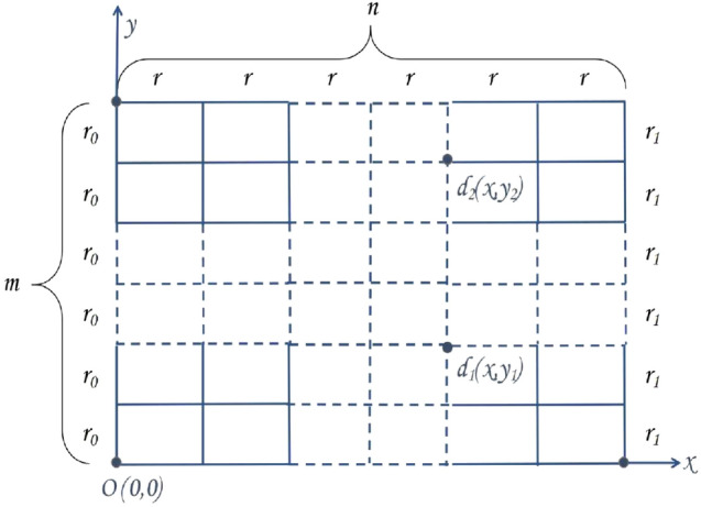
An  rectangular resistor network, except the right boundary resistor in the vertical direction is
  , its horizontal and vertical resistors are r and
  , respectively.
Fig. 2.
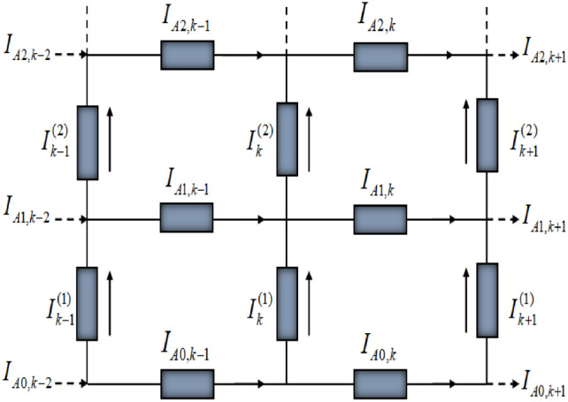
Partial resistor network with current directions and parameters.
The equivalent resistance  between two arbitrary nodes
  and
and  in an
in an  rectangular resistor network is shown below
 |
1 |
where
 |
2 |
 |
3 |
Tan analyzed and studied the resistor network, and established a resistor network model based on Kirchhoff’s law. The general matrix equation is given below.
 |
4 |
the function  is defined as
  ,
,  and
and  are the
  column matrices which can be described as
 |
where  is the element of
  when injecting current J at
  and exiting at
  ,
,
 |
5 |
where  .
.
New formula of equivalent resistance represented by Chebyshev polynomials
For the equivalent resistance formula (1), Eq. (2) is an explanation of the symbols in formula (1), which involves complex exponential operations and has high computational complexity. In order to improve the calculation efficiency of equivalent resistance, this section introduces the improved equivalent resistance formula using the Chebyshev polynomial of the second kind.
Let the current J be input at  and output at
  , the equivalent resistance between two nodes in the
  resistor network is given by
 |
6 |
where
 |
7 |
 |
8 |
 |
9 |
 |
10 |
Derivation of the new equivalent resistance formula
In this section, Chebyshev polynomial of the second kind is adopted to signify the Horadam sequence64, which improves the calculation efficiency. And the discrete sine transform is introduced to obtain the solution of the model equations, the equivalent resistance formula is re-derived.
Horadam sequence represented by Chebyshev polynomials
Horadam sequence contains the following conditions:
 |
11 |
where  ,
,  is the set of all natural numbers and
  is the set of all complex numbers.
Horadam sequence65 represented by Chebyshev polynomial of the second kind is
 |
12 |
where
 |
13 |
is the Chebyshev polynomial of the second kind66.
Equation (13) contains complex numbers, since  , which in this study can be described as
 |
14 |
where  , i is the imaginary unit.
Discrete sine transform
Let
 |
15 |
The matrix  is a well-known discrete sine transform of the first kind (DST-I)67,68.
  is an orthogonal matrix, and the inverse and transpose of
  are still itself, i.e.
 |
16 |
For Eq. (5), perform the following orthogonal diagonalization
 |
17 |
therefore,
 |
18 |
where
 |
19 |
From Eq. (17), it is known that the matrix  is similar to
  , so
, so  is the eigenvalue of
  .
.
By left-multiplying Eq. (17) by  , we obtain the following equation
 |
i.e.,
 |
20 |
where  ,
,
 |
Equation (20) can be expressed as
 |
21 |
Based on Eq. (21), the eigenvector  corresponding to
  is obtained.
Let
 |
22 |
where the  column matrix
  is
is
 |
According to Eqs. (16) and (22), it can be obtained as follows
 |
23 |
Considering the boundary conditions of the rectangular resistor network, the following current equations are established based on Kirchhoff’s law
 |
24 |
 |
25 |
where  ,
,  is given by Eq.(5) and
  is the
  identity matrix.
Equations (4), (24) and (25) are multiplied by  on the left, and then combine with Eq. (22) to obtain the following equations
 |
26 |
 |
27 |
 |
28 |
where
 |
29 |
Solving the matrix equations
The homogeneous equation of Eq. (26) is expressed as follows
 |
let  ,
,  ,
,  and
and  in Eq. (11), combine Eqs. (12), (13) and (14) to get the following equation
 |
30 |
where
 |
31 |
 is defined by Eq. (19).
Next, consider the solution of Eq. (26) with the current input at  and output at
  . According to Eq. (30), the piecewise solutions of Eq. (26) are obtained as follows
 |
32 |
 |
33 |
 |
34 |
where  is defined by Eq. (31).
Based on Eqs. (27), (28), (32), (33) and (34), the expression of  can be described as
 |
35 |
From Eqs. (15), (23) and (35), the sum of currents between two nodes can be expressed as
 |
36 |
According to Ohm’s law, the equivalent resistance formula between two nodes is described as
 |
37 |
due to Eqs. (36) and (37), the explicit formula (6) for the equivalent resistance between two nodes can be obtained.
Demonstrating the equivalent resistance formulas for some special cases
Formula (6) is a general conclusion for rectangular resistor networks that includes all cases. The influence of different variables on the explicit equivalent resistance formula is analyzed from two aspects as follows, and 3D views are used to demonstrate them.
Influence of current input node on equivalent resistance
This part gives examples of the change of equivalent resistance when the current input node is different.
Case 1. Assume that the current J is input at node  , and the current flows out of the resistor network at node
  , the equivalent resistance between nodes
  and
and  can be written as
 |
where  ,
,  and
and  are defined by Eqs. (7), (8) and (8), respectively.
When  and
and  , in other words,
  , the following formula is obtained
 |
38 |
where
 |
39 |
 |
40 |
 |
41 |
 |
42 |
 |
A three-dimensional view of Eq. (38) is shown in Fig. 3.
Fig. 3.
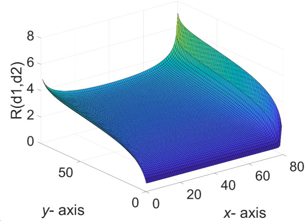
The 3D equivalent resistance distribution diagram of  in Eq. (38).
Case 2. If the current J is input at node  in the resistor network and output at node
  , the equivalent resistance formula between
  and
and  can be characterized as
 |
43 |
where  ,
,  and
and  are defined by Eqs. (7), (8) and (8), respectively.
In a resistor network of size  , when
  and
and  , Eq. (43) is defined as
 |
44 |
where  ,
,  ,
,  and
and  (
( ) are the same as Eqs. (39), (40), (41) and (42), respectively.
A three-dimensional view of Eq. (44) is shown in Fig. 4.
Fig. 4.
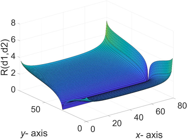
The 3D equivalent resistance distribution diagram of  in Eq. (44).
Case 3. Assume that the current J is input into the resistor network,  is the input node of the current and
  is the output node, then the equivalent resistance formula between these two nodes can be expressed as
 |
45 |
where  ,
,  and
and  are defined by Eqs. (7), (8) and (8), respectively.
When  and
and  , Eq. (45) is described in the resistor network of size
  as
as
 |
46 |
where  ,
,  ,
,  and
and  (
( ) are the same as Eqs. (39), (40), (41) and (42), respectively.
A three-dimensional view of Eq. (46) is shown in Fig. 5.
Fig. 5.
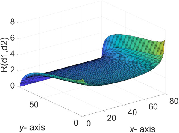
The 3D equivalent resistance distribution diagram of  in Eq. (46).
Effect of resistivity h ( ) on equivalent resistance
The following discusses the values of the equivalent resistance between nodes  and
and  on each vertical axis of the resistor network when the value of
  at the current input node
  remains constant and the resistivity h is different. The resistivity here is the ratio of r to
  , denoted by h, i.e.,
  .
.
Case 4. If the node  in the resistor network is used as the input node of the current J, and
  is used as the output node, then the equivalent resistance formula between the two nodes
  and
and  is written as
 |
where  ,
,  and
and  are defined by Eqs. (7), (8) and (8), respectively.
When  and
and  the following formula is obtained
 |
47 |
where  ,
,  ,
,  and
and  (
( ) are the same as Eqs. (39), (40), (41) and (42), respectively.
A three-dimensional view of Eq. (47) is shown in Fig. 6.
Fig. 6.
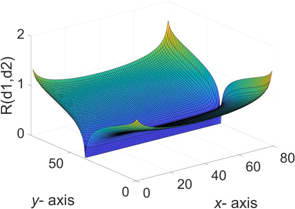
The 3D equivalent resistance distribution diagram of  in Eq. (47).
Case 5. Assume that the current  flows from a fixed input node
  to a fixed output node
  in a rectangular resistor network.
In this case, given  , in other words,
  the equivalent resistance formula between these two nodes is described as
 |
48 |
where  ,
,  and
and  are defined by Eqs. (7), (8) and (8), respectively.
When the size of the resistor network is  , ie
, ie  ,
,  , Eq. (48) is represented as
 |
49 |
where  ,
,  ,
,  and
and  (
( ) are the same as Eqs. (39), (40), (41) and (42), respectively.
A three-dimensional view of Eq. (49) is shown in Fig. 7.
Fig. 7.
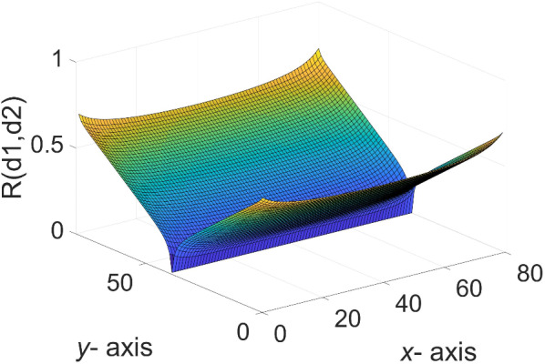
The 3D equivalent resistance distribution diagram of  in Eq. (49).
Case 6. Suppose the current  flows into resistor network through
  and out at
  , at this time, the equivalent resistance formula between
  and
and  can be expressed as
 |
where  ,
,  and
and  are defined by Eqs. (7), (8) and (8), respectively.
Let  , that is ,
  the following formula is obtained
 |
50 |
where  ,
,  ,
,  and
and  (
( ) are the same as Eqs. (39), (40), (41) and (42), respectively.
A three-dimensional view of Eq. (50) is shown in Fig. 8.
Fig. 8.
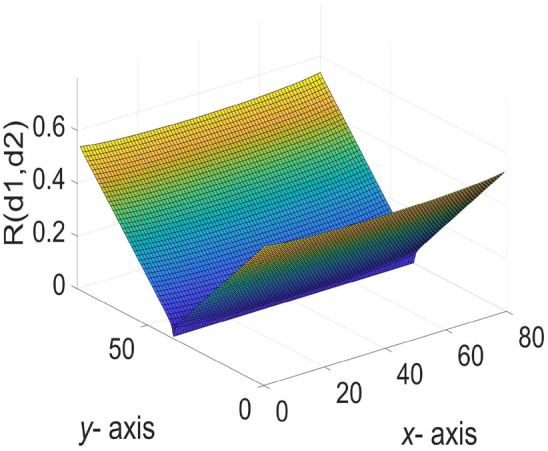
The 3D equivalent resistance distribution diagram of  in Eq. (50).
Calculation efficiency of different equivalent resistance formulas
In this section, examples are shown that demonstrate the computational efficiency of two equivalent resistor formulas. In the  rectangular resistor network,
  and
and  represent the current input and output nodes, respectively. In the experiment, the
  value of the input node is fixed, and each
  node on each vertical axis is traversed. The CPU processing times
  and
and  represent the time required to calculate the equivalent resistance using formula (1) and formula (6), respectively, and demonstrate the calculation efficiency of the two different formulas.
These experiments are done on an Intel Core i7-12700H laptop with 2.30 GHz CPU and NVIDIA GeForce RTX 3060 GPU. In the following tables, the calculation time is in seconds, “ ” denotes the scale of resistor network, “*” and the dashed empty bar indicate computer memory overflow.
When  ,
,  , the CPU time spent calculating the equivalent resistance by formula (1) and formula (6), respectively is shown in Fig. 9.
Fig. 9.
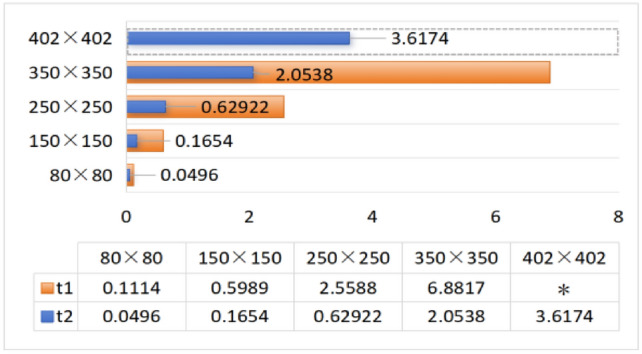
CPU time to calculate equivalent resistance using formula (1) and formula (6), respectively.
When  ,
,  , the CPU time spent calculating the equivalent resistance by formula (1) and formula (6), respectively is shown in Fig. 10.
Fig. 10.
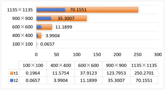
CPU time to calculate equivalent resistance using formula (1) and formula (6), respectively.
When  ,
,  , the CPU time spent calculating the equivalent resistance by formula (1) and formula (6), respectively is shown in Fig. 11.
Fig. 11.
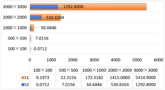
CPU time to calculate equivalent resistance using formula (1) and formula (6), respectively.
When  ,
,  , the CPU time spent calculating the equivalent resistance by formula (1) and formula (6), respectively is shown in Fig. 12.
Fig. 12.
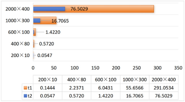
CPU time to calculate equivalent resistance using formula (1) and formula (6), respectively.
When  ,
,  , the CPU time spent calculating the equivalent resistance by formula (1) and formula (6), respectively is shown in Fig. 13.
Fig. 13.
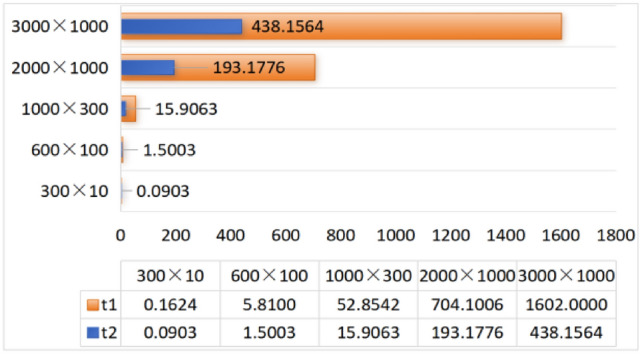
CPU time to calculate equivalent resistance using formula (1) and formula (6), respectively.
When  ,
,  , the CPU time spent calculating the equivalent resistance by formula (1) and formula (6), respectively is shown in Fig. 14.
Fig. 14.
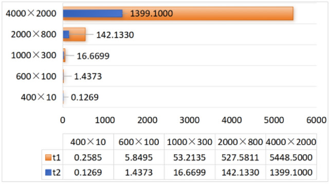
CPU time to calculate equivalent resistance using formula (1) and formula (6), respectively.
It can be clearly seen from the above six visualization charts that the computational efficiency of the improved formula (6) is higher than that of formula (1), and as the scale of the resistor network increases, the advantages of formula (6) become more obvious. As the resistivity decreases, the size of the data that can be processed using the equivalent resistance formula increases.
Conclusion
This paper uses Chebyshev polynomial of the second kind to improve the equivalent resistance formula of the  rectangular resistor network. Some special and interesting equcations of the resistor network, such as Eqs. (38), (44), (46), (47), (49) and (50) were introduced. To provide a visual representation, their three-dimensional views were plotted using MATLAB. Finally, several comparison tables were provided to show the calculation efficiency of two equivalent resistance formulas. The design philosophy and formulas presented in this study will inspire further research in fields such as neural networks and other related areas.
Acknowledgements
The research was Supported by the National Natural Science Foundation of China (Grant No.12101284), the Natural Science Foundation of Shandong Province (Grant No. ZR2022MA092) and the Department of Education of Shandong Province (Grant No.2023KJ214).
Author contributions
Xiao-Yu, Jiang and Yan-Peng, Zheng conceived the project, performed and analyzed formulae calculations. Ru, Wang and De-liang, Xiang validated the correctness of the formula calculation, and realized graph drawing. Zhao-Lin, Jiang proposed an improved formula for calculating equivalent resistance. All authors contributed equally to the manuscript.
Data availibility
All data generated or analysed during this study are included in this article.
Competing interests
The authors declare no competing interests.
Footnotes
Publisher's note
Springer Nature remains neutral with regard to jurisdictional claims in published maps and institutional affiliations.
Contributor Information
Xiaoyu Jiang, Email: jxy19890422@sina.com.
Yanpeng Zheng, Email: zhengyanpeng0702@sina.com.
References
-
1.Tan, Z.-Z., Zhou, L. & Yang, J.-H. The equivalent resistance of a
 cobweb network and its conjecture of an
  cobweb network. J. Phys. A: Math. Theor.46(19), 195202 (2013). [Google Scholar]
 -
2.Tan, Z.-Z. Recursion-transform method to a non-regular
 cobweb with an arbitrary longitude. Sci. Rep.5, 11266 (2015).
[DOI] [PMC free article] [PubMed] [Google Scholar]
 - 3.Tan, Z.-Z., Essam, J. W. & Wu, F. Y. Two-point resistance of a resistor network embedded on a globe. Phys. Rev. E.90(1), 012130 (2014). [DOI] [PubMed] [Google Scholar]
-
4.Essam, J. W., Tan, Z.-Z. & Wu, F. Y. Resistance between two nodes in general position on an
 fan network. Phys. Rev. E.90(3), 032130 (2014). [DOI] [PubMed] [Google Scholar]
 -
5.Tan, Z.-Z. & Fang, J.-H. Two-point resistance of a cobweb network with a
 boundary. Commun. Theor. Phys.63(1), 36–44 (2015). [Google Scholar]
 -
6.Tan, Z.-Z. Theory on resistance of
 cobweb network and its application. Int. J. Circ. Theor. Appl.43(11), 1687–1702 (2015). [Google Scholar]
 -
7.Tan, Z.-Z. Two-point resistance of an
 resistor network with an arbitrary boundary and its application in RLC network. Chin. Phys. B25(5), 050504 (2016). [Google Scholar]
 -
8.Tan, Z.-Z. Recursion-transform method and potential formulae of the
 cobweb and fan networks. Chin. Phys. B26(9), 090503 (2017). [Google Scholar]
 -
9.Tan, Z., Tan, Z.-Z. & Chen, J. Potential formula of the nonregular
 fan network and its application. Sci. Rep.8, 5798 (2018).
[DOI] [PMC free article] [PubMed] [Google Scholar]
 -
10.Tan, Z. & Tan, Z.-Z. Potential formula of an
 globe network and its application. Sci. Rep.8(1), 9937 (2018).
[DOI] [PMC free article] [PubMed] [Google Scholar]
 - 11.Hadad, Y., Soric, J. C. & Khanikaev, A. B. Self-induced topological protection in nonlinear circuit arrays. Nat. Electron.1, 178–182 (2018). [Google Scholar]
- 12.Zhang, D. et al. Impact damage localization and mode identification of CFRPs panels using an electric resistance change method. Compos. Struct.276, 114587 (2021). [Google Scholar]
- 13.Kirchhoff, G. Ueber die Aufölsung der Gleichungen, auf welche man bei der Untersuchung der linearen Vertheilung galvanischer Ströme geführt wird. Ann. Phys.148, 497–508 (1847). [Google Scholar]
- 14.Winstead, V. & Demarco, C. L. Network essentiality. IEEE T. Circ.-I.60(3), 703–709 (2012). [Google Scholar]
- 15.Ferri, G. & Antonini, G. Ladder-network-based model for interconnects and transmission lines time delay and cutoff frequency determination. J. Circuit. Syst. Comp.16, 489–505 (2007). [Google Scholar]
- 16.Owaidat, M. Q., Hijjawi, R. S. & Khalifeh, J. M. Network with two extra interstitial resistors. Int. J. Theor. Phys.51, 3152–3159 (2012). [Google Scholar]
- 17.Kirkpatrick, S. Percolation and conduction. Rev. Mod. Phys.45, 497–508 (1973). [Google Scholar]
- 18.Pennetta, C. et al. Biased resistor network model for electromigration failure and related phenomena in metallic lines. Phys. Rev. B70, 174305 (2004). [Google Scholar]
- 19.Kook, W. Combinatorial Green’s function of a graph and applications to networks. Adv. Appl. Math.46, 417–423 (2011). [Google Scholar]
- 20.Shi, Y. et al. Novel discrete-time recurrent neural networks handling discrete-form time-variant multi-augmented Sylvester matrix problems and manipulator application. IEEE Trans. Neur. Net. Lear.33(2), 587–599 (2022). [DOI] [PubMed] [Google Scholar]
- 21.Shi, Y., Zhao, W.-H., Li, S., Li, B. & Sun, X.-B. Novel discrete-time recurrent neural network for robot manipulator: a direct discretization technical route. IEEE Trans. Neur. Net. Lear.34(6), 2781–2790 (2021). [DOI] [PubMed] [Google Scholar]
- 22.Liu, K.-P. et al. Five-step discrete-time noise-tolerant zeroing neural network model for time-varying matrix inversion with application to manipulator motion generation. Eng. Appl. Artif. Intel.103, 104306 (2021). [Google Scholar]
- 23.Sun, Z.-B. et al. Noise-suppressing zeroing neural network for online solving time-varying matrix square roots problems: A control-theoretic approach. Expert. Syst. Appl.192, 116272 (2022). [Google Scholar]
- 24.Jin, L., Qi, Y.-M., Luo, X., Li, S. & Shang, M.-S. Distributed competition of multi-robot coordination under variable and switching topologies. IEEE Trans. Autom. Sci. Eng.19(4), 3575–3586 (2022). [Google Scholar]
- 25.Jin, L., Zhang, Y.-N., Li, S. & Zhang, Y.-Y. Modified ZNN for time-varying quadratic programming with inherent tolerance to noises and its application to kinematic redundancy resolution of robot manipulators. IEEE Trans. Ind. Electron.63(11), 6978–6988 (2016). [Google Scholar]
- 26.Jin, L., Zheng, X. & Luo, X. Neural dynamics for distributed collaborative control of manipulators with time delays. IEEE-CAA J. Autom.9(5), 854–863 (2022). [Google Scholar]
- 27.Wang, X., Che, M. & Wei, Y. Complex-valued neural networks for the Takagi vector of complex symmetric matrices. Neuron223, 77–85 (2017). [Google Scholar]
- 28.Klein, D. J. & Randi, M. Resistance distance. J. Math. Chem.12, 81–95 (1993). [Google Scholar]
- 29.Giordano, S. Disordered lattice networks: general theory and simulations. Int. J. Circ. Theor. Appl.33, 519–540 (2005). [Google Scholar]
- 30.Wu, F. Y. Theory of resistor networks: the two-point resistance. J. Phys. A: Math. Gen.37, 6653 (2004). [Google Scholar]
- 31.Tzeng, W. J. & Wu, F. Y. Theory of impedance networks: the two-point impedance and LC resonances. J. Phys. A: Math. Gen.39, 8579 (2006). [Google Scholar]
-
32.Essam, J. W. & Wu, F. Y. The exact evaluation of the corner-to-corner resistance of an
 resistor network: asymptotic expansion. J. Phys. A: Math. Theor.42, 025205 (2008). [Google Scholar]
 -
33.Izmailian, N. S. & Huang, M.-C. Asymptotic expansion for the resistance between two maximum separated nodes on an
 by
by  resistor network. Phys. Rev. E.82, 011125 (2010). [DOI] [PubMed] [Google Scholar]
 - 34.Lai, M.-C. & Wang, W.-C. Fast direct solvers for Poisson equation on 2D polar and spherical geometries. Numer. Meth. Part. D. E.18, 56–68 (2002). [Google Scholar]
- 35.Borges, L. & Daripa, P. A fast parallel algorithm for the Poisson equation on a disk. J. Comput. Phys.169, 151–192 (2001). [Google Scholar]
- 36.Izmailian, N. S., Kenna, R. & Wu, F. Y. The two-point resistance of a resistor network: a new formulation and application to the cobweb network. J. Phys. A: Math. Theor.47, 035003 (2014). [Google Scholar]
- 37.Izmailian, N. S. & Kenna, R. A generalised formulation of the Laplacian approach to resistor networks. J. Stat. Mech: Theor. E.9, 1742–5468 (2014). [Google Scholar]
- 38.Izmailian, N. S. & Kenna, R. The two-point resistance of fan networks. Chin. J. Phys.53(2), 040703 (2015). [Google Scholar]
- 39.Chair, N. Trigonometrical sums connected with the chiral Potts model, verlinde dimension formula, two-dimensional resistor network, and number theory. Ann. Phys.341, 56–76 (2014). [Google Scholar]
- 40.Chair, N. The effective resistance of the N-cycle graph with four nearest neighbors. J. Stat. Phys.154, 1177–1190 (2014). [Google Scholar]
- 41.Cserti, J. Application of the lattice Green’s function for calculating the resistance of an infinite network of resistors. Am. J. Phys.68, 896–906 (2000). [Google Scholar]
- 42.Kook, W. Combinatorial Green’s function of a graph and applications to networks. Adv. Appl. Math.46, 417–433 (2011). [Google Scholar]
- 43.Katsura, S. & Inawashiro, S. Lattice Green’s functions for the rectangular and the square lattices at arbitrary points. J. Math. Phys.12, 1622 (1971). [Google Scholar]
- 44.Bairamkulov, R. & Friedman, E. G. Effective resistance of finite two-dimensional grids based on infinity mirror technique. IEEE T. Circuits-I67(9), 3224–3233 (2020). [Google Scholar]
- 45.Bairamkulov, R. & Friedman, E. G. Effective resistance of two-dimensional truncated infinite mesh structures. IEEE T. Circuits-I66(11), 4368–4376 (2019). [Google Scholar]
- 46.Kose, S. & Friedman, E. G. Effective resistance of a two layer mesh. IEEE T. Circuits-II58(11), 739–743 (2011). [Google Scholar]
-
47.Jiang, X.-Y., Zhang, G.-J., Zheng, Y.-P. & Jiang, Z.-L. Explicit potential function and fast algorithm for computing potentials in
 conic surface resistor network. Expert. Syst. Appl.238, 122157 (2024). [Google Scholar]
 -
48.Zhou, Y.-F., Zheng, Y.-P., Jiang, X.-Y. & Jiang, Z.-L. Fast algorithm and new potential formula represented by Chebyshev polynomials for an
 globe network. Sci. Rep.12(1), 21260 (2022).
[DOI] [PMC free article] [PubMed] [Google Scholar]
 - 49.Jiang, Z.-L., Zhou, Y.-F., Jiang, X.-Y. & Zheng, Y.-P. Analytical potential formulae and fast algorithm for a horn torus resistor network. Phys. Phys. E.107(4), 044123 (2023). [DOI] [PubMed] [Google Scholar]
- 50.Zhou, Y.-F., Jiang, X.-Y., Zheng, Y.-P. & Jiang, Z.-L. Exact novel formulas and fast algorithm of potential for a hammock resistor network. Aip. Adv.13, 9 (2023). [Google Scholar]
-
51.Zhao, W.-J., Zheng, Y.-P., Jiang, X.-Y. & Jiang, Z.-L. Two optimized novel potential formulas and numerical algorithms for
 cobweb and fan resistor networks. Sci. Rep.13(1), 12417 (2023).
[DOI] [PMC free article] [PubMed] [Google Scholar]
 -
52.Meng, X., Jiang, X.-Y., Zheng, Y.-P. & Jiang, Z.-L. A novel formula for representing the equivalent resistance of the
 cylindrical resistor network. Sci. Rep.14(1), 21254 (2024).
[DOI] [PMC free article] [PubMed] [Google Scholar]
 - 53.Wang, J.-J., Zheng, Y.-P. & Jiang, Z.-L. Norm equalities and inequalities for tridiagonal perturbed toeplitz operator matrices. J. Appl. Anal. Comput.13(2), 671–683 (2023). [Google Scholar]
- 54.Fu, Y.-R., Jiang, X.-Y., Jiang, Z.-L. & Jhang, S. Inverses and eigenpairs of tridiagonal Toeplitz matrix with opposite-bordered rows. J. Appl. Anal. Comput.10(4), 1599–1613 (2020). [Google Scholar]
- 55.Fu, Y.-R., Jiang, X.-Y., Jiang, Z.-L. & Jhang, S. Analytic determinants and inverses of Toeplitz and Hankel tridiagonal matrices with perturbed columns. Spec. Matrices.8, 131–143 (2020). [Google Scholar]
- 56.Wei, Y.-L., Zheng, Y.-P., Jiang, Z.-L. & Shon, S. The inverses and eigenpairs of tridiagonal Toeplitz matrices with perturbed rows. J. Appl. Math. Comput.68, 623–636 (2022). [Google Scholar]
- 57.Wei, Y.-L., Jiang, X.-Y., Jiang, Z.-L. & Shon, S. On inverses and eigenpairs of periodic tridiagonal Toeplitz matrices with perturbed corners. J. Appl. Anal. Comput.10(1), 178–191 (2020). [Google Scholar]
- 58.Wei, Y.-L., Zheng, Y.-P., Jiang, Z.-L. & Shon, S. A study of determinants and inverses for periodic tridiagonal Toeplitz matrices with perturbed corners involving Mersenne numbers. Mathematics.7(10), 893 (2019). [Google Scholar]
- 59.Wei, Y.-L., Jiang, X.-Y., Jiang, Z.-L. & Shon, S. Determinants and inverses of perturbed periodic tridiagonal Toeplitz matrices. Adv. Differ. Equ.2019(1), 410 (2019). [Google Scholar]
- 60.Jiang, Z.-L., Wang, W.-P., Zheng, Y.-P., Zuo, B.-S. & Niu, B. Interesting explicit expressions of determinants and inverse matrices for Foeplitz and Loeplitz Matrices. Mathematics.7(10), 939 (2019). [Google Scholar]
- 61.Meng, Q.-Y., Zheng, Y.-P. & Jiang, Z.-L. Exact determinants and inverses of (2,3,3)-Loeplitz and (2,3,3)-Foeplitz matrices. Comput. Appl. Math.41, 35 (2022). [Google Scholar]
- 62.Meng, Q.-Y., Zheng, Y.-P. & Jiang, Z.-L. Determinants and inverses of weighted Loeplitz and weighted Foeplitz matrices and their applications in data encryption. J. Appl. Math. Comput.68, 3999–4015 (2022). [Google Scholar]
- 63.Meng, Q.-Y., Jiang, X.-Y. & Jiang, Z.-L. Interesting determinants and inverses of skew Loeplitz and Foeplitz matrices. J. Appl. Anal. Comput.11, 2947–2958 (2021). [Google Scholar]
- 64.Horadam, A. F. Basic properties of a certain generalized sequence of numbers. Fibonacci Q.3, 161–176 (1965). [Google Scholar]
-
65.Udrea, G. A note on the sequence
 of A.F. Horadam. Port. Math.53, 143–156 (1996). [Google Scholar]
 - 66.Mason, J. C., Handscomb, D. C. Chebyshev Polynomials (Chapman & Hall, 2002).
- 67.Garcia, S. R. & Yih, S. Supercharacters and the discrete Fourier, cosine, and sine transforms. Commun. Algebra.46(9), 3745–3765 (2018). [Google Scholar]
- 68.Sanchez, V., Peinado, A. M., Segura, J. C., Garcia, P. & Rubio, A. J. Generating matrices for the discrete sine transforms. IEEE T. Signal. Process.44(10), 2644–2646 (1996). [Google Scholar]
Associated Data
This section collects any data citations, data availability statements, or supplementary materials included in this article.
Data Availability Statement
All data generated or analysed during this study are included in this article.


