Abstract
In this paper, a widely used disc-buckle support frame is taken as the object, and parallel positive and negative bending tests are carried out on the connection nodes of the disc-buckle support frame. The failure mode, stress distribution law and bending resistance of the connection nodes of the disc-buckle support frame are systematically studied, and the connection characteristics of the connection nodes of the disc-buckle support frame are verified to be semirigid connections. On the basis of the test results, a finite element model of the connection joint of the disc buckle frame is established, and the calculation results are in good agreement with the test results. Based on the established finite element model, parametric analysis was carried out on the influencing factors, such as the depth of the pin inserted into the connecting disc, the thickness of the connecting disc. The insertion depth of the pin cannot exceed 29 mm, and the bearing capacity of the joint will be reduced when the insertion depth exceeds 29 mm. The bearing capacity of the joint increases with the increase of the thickness of the connecting disc.
Keywords: Inserting-type support frame, Theoretical calculation, Bending test, Finite element
Subject terms: Civil engineering, Mechanical engineering
Introduction
In the process of building construction, steel pipe scaffolds have become an indispensable auxiliary tool. Scaffolds play two main roles in the process of building construction. The first is the external scaffold system, and the other is the support system of the building when pouring concrete1,2. However, because the mechanical performance of the scaffold has not yet formed a more unified calculation method, which also leads to some safety accidents in the construction process of the scaffold, as shown in Fig. 1.
Fig. 1.
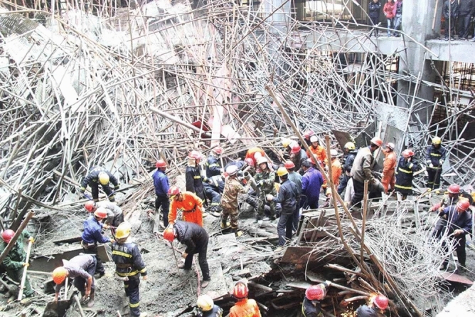
Collapse accident of the high-formwork support frame.
In Reference3 and Reference4, the stability calculation method of formwork support is given, but this calculation method has been questioned by scholars5. This also led many researchers to study the mechanical properties of the scaffold support system. Sevim6, Zhao7 and Rezaiee-Pajand8 shown that the connection joints in the disc-buckled high-rise support system had semi-rigid connection characteristics, and the bending moment-rotation curve of the joints was nonlinear. Ding9 analyzed the collapse accident of the formwork support frame, and found that the main reasons were the serious defects of the vertical rod, the unreasonable number and setting mode of the inclined rod, and the external impact load. Huang10 carried out strain monitoring on the vertical rod of the support frame and obtained the variation law of its axial force. Then, the lateral displacement is measured by the linear variable differential transformer method. The relationship between the above data is summarized and analyzed, and the failure mode of the bar is obtained. Chen11 found that the joint stiffness, initial defects and erection methods have an impact on the bearing capacity of the high support system. Zhao12 deduced the effective length coefficient of semi-rigid connection with lateral displacement and applied it to the calculation of stable bearing capacity on the basis of considering the semi-rigid property of joints. Peng13 found that the number of horizontal bars at the joint will affect the rotational stiffness of the joint through experimental research, and the bending moment-rotation curve of any joint can be fitted with a three-linear model. Zhao14,15 found that the mechanical properties of the connection joints are very complex due to the need for rapid assembly of the formwork support during construction, and the semi-rigidity of the joints has a significant impact on the stable bearing capacity of the overall support system. Peng13 conducted an experimental study on the vertical ultimate bearing capacity of the basic force unit of the socket-type steel tube support frame, and obtained the relationship between the joint wedge tightness and the ultimate bearing capacity. Peng16 deduced the moment–curvature relationship of steel tubular scaffolds through a large amount of experimental data, and on this basis, a second-order inelastic analysis method was proposed for application to the hinged form of a formwork support system. Chan17,18 proposed that it is not accurate to use completely ideal rigid and hinged connection forms in the calculation of semirigid frame joints, and the existing test data are not sufficient to evaluate the connection stiffness of joints. After analyzing the existing experimental data and theoretical research, he proposed a relatively approximate mathematical calculation method. First, he estimated the effective length of the scaffold member and then used the corresponding relationship between the effective length and the stiffness of the joint to calculate the stiffness of the joint. Yu19,20 studied the change in the buckling curve of door-type steel scaffolds according to experimental results. On the basis of experimental and numerical studies, they further studied the structural instability of multistory door-type modular steel scaffolds. Lightfoot21 used plastic analysis and elastic buckling analysis to analyze the overall bearing stability of a formwork support system. Homes22 deeply analyzed the full-scale model of a scaffold and analyzed the stability bearing capacity of the scaffold system under vertical loading and horizontal loading. Chen23 performed an ultimate bearing capacity test of a disc-buckle connection point. On the basis of the test results, finite element software was used to model and analyze the disc-buckle steel pipe support frame. According to the test results and simulation comparison analysis, it is concluded that the disc-buckle formwork support structure has good systematicity. The number of spans and steps has little effect on the stability of the support structure. The main factor affecting the overall stability of the disc-buckle formwork support structure is the length of the cantilever section at the top of the pole. Hu24 conducted an experimental study on the inserting-type steel pipe support frame of a construction platform and compared the characteristics of the inserting-type, door-type and steel tube–coupler scaffolds in detail. The structural form of the bolt-type steel pipe support frame was studied, and the internal stress distribution law of the inserting-type steel pipe support frame during the construction of the installation platform was noted.
Through the above research, it is found that the research on the stability of high support system is mostly focused on the fastener support system25,26. The influence of manufacturing error on the bearing capacity of the joint is not much, especially based on the semi-rigid characteristics of the joint, the failure mode, stress distribution law and bending resistance of the joint are studied. In this paper, the disc-buckle scaffold joint is taken as the research object, and the influence of some defects caused by the scaffold fabrication error on the mechanical performance of the joint is studied. Based on the test results, the finite element model of the disc-buckle scaffold is established, and the parametric analysis of the disc-buckle scaffold is carried out to grasp the influence of relevant parameters on the bending resistance of the joint and optimize the design parameters of the joint components.
Theoretical calculation of the insertion-type support frame
Internal force transmission path of the formwork support
In terms of the internal force distribution and transmission, the inserting-type high-support formwork can be summarized in terms of the following five points. During the construction process, the live load and the dead load can be divided into horizontal load and vertical load.
The horizontal load is first transferred to the U-shaped top support by the rectangular tube or wood above the formwork and the vertical poles, and then the load is transferred to the foundation by the vertical poles.
The vertical load is transmitted to the horizontal poles by the wooden square on the upper part of the formwork and the vertical poles and then transmitted to the vertical poles through the connecting disc; finally, the load is transmitted to the foundation by the vertical poles.
The vertical bar connection of the insert-type formwork support is the same axis socket, and the joint is located in the frame plane. The joint has mechanical properties such as shear resistance, bending resistance and torsion resistance, so the connection structure is stable, and the bearing capacity is large.
The horizontal poles mainly bear the horizontal force generated by the frame during the construction process, which can reduce the slenderness ratio of the vertical poles and further improve the stability and bearing capacity of the vertical poles.
The diagonal brace and the scissor brace are the structural measures of the support frame, which is beneficial for improving the stability of the support frame and limiting the lateral displacement of the frame body so that the vertical poles of the high support frame are closer to the vertical axial force component.
Calculation theory of formwork support
Inserting-type steel pipe scaffolds are a new support frame system introduced from abroad. The calculation theory of its mechanical properties is relatively imperfect and lacks corresponding technical specifications in China. The insertion-type steel pipe scaffold is derived from the ordinary steel tube–coupler scaffold. Compared with those of steel tube–coupler scaffolds, the mechanical properties and economy of these materials have been optimized. Therefore, we can learn from research on steel tube–coupler scaffolds and then study the calculation theory of inserting-type scaffolds. Through the analysis of the relevant literature on scaffolding, whether it is a steel tube–coupler or an inserting-type formwork support, the node property of the connection between the vertical poles and the horizontal poles is an important factor in determining the effective length of the vertical bar, so the property of the nodes should be considered when calculating the internal force of the support. At present, there are three methods for calculating the internal force of the support frame according to the property of the node in China, namely, the hinged calculation method, rigid calculation method and semirigid calculation method27,28.
(1) Hinged model
The hinged model is based on the simplification of the formwork support from the three-dimensional system to the plane system. The principle of this model is to simplify the nodes of the scaffold as hinges for research and calculation. China's current technical safety specifications for scaffolding and related technical safety specifications in Japan and the United Kingdom are based on this calculation method. The calculation method regards the connection node between the vertical poles and the horizontal poles as hinged, and the stability calculation of the whole frame is simplified to the calculation of a single vertical pole in a step range. Therefore, this calculation method is also called the single pole hinged calculation method. The design method of steel pipe scaffolds in China is the probability limit state design theory, and the partial coefficient is used for calculation29.
(2) The calculation of the stability of the upright poles:
When the wind load is not combined:
 |
1 |
 |
2 |
When combined with the wind load:
 |
3 |
where N is the axial force design value of the compression member.
 —The stability coefficient of the vertical poles under compression is determined according to the slenderness ratio λ of the vertical bar.
W—Modulus of the section.
A—Foundation bottom surface area or cross-sectional area.
 —Bending moment generated by the wind load design value.
f —The design value of the compressive strength of steel.
In the formula,  is the effective length of the vertical pole of the formwork support, and
  is the radius of gyration of the cross-section. The correction coefficient η and the reduction coefficient k should be considered for the length
  of the formwork support poles. According to the following formula calculation and taking the larger value:
 |
4 |
 |
5 |
where  is the calculated length of the vertical tube.
 —Bracket pole length correction coefficient.
 —The maximum vertical step distance of the upright pole.
 —The vertical step distance between the top or bottom horizontal poles of the stand rod of the bracket is generally less than the maximum step distance by one inserting-type distance.
k—Length reduction coefficient of cantilever end.
 —The distance between the top or bottom adjustable support point and the centerline of the top or bottom horizontal poles.
The formula for calculating the axial force design of the steel pipe scaffold pole is:
Uncombined wind load calculation:
 |
6 |
Combined wind load calculation:
 |
7 |
where  is the standard value of the self-weight load of the frame body.
 —Standard value of self-weight load of components.
 —Standard value of construction load.
(3) The American standard considers the initial defect condition of the member when calculating the scaffold30. The calculation method is as follows:
 |
8 |
In the formula:
 —The safety factor is generally set to 2.0.
 —Axial stress of the steel tube.
 —Yield strength of the steel pipe.
 —0.3.
—0.3.
 —Euler critical force,
 .
.
 —Slenderness ratio.
(4) The Japanese standard method for calculating scaffolding is as follows30:
 |
9 |
where  is the design value of the steel compressive strength.
 —Effective cross-sectional area of the steel tube.
 —Buckling coefficient of the compression poles.
 —Axial force of the compression poles when subjected to force.
 —Reduction factor of the steel tube joints.
Through the above calculation theory, it can be found that for both the Chinese code and the American or Japanese code, in the design and calculation of the support frame poles, the vertical poles are multiplied by a safety factor in different forms. The Chinese specification guarantees the safety of the vertical poles by adjusting the calculated length of the vertical poles. The American specifications are directly multiplied by a safety factor of 2, and the Japanese specifications guarantee the safety of the vertical pole design by setting a  . In this paper, finite element calculations are used to verify the change in the axial force of the vertical poles when the operation or bearing capacity of the base varies during the construction process and to verify the rationality of the theoretical safety factor.
(5) Calculation model of a rigid frame with lateral displacement
This method is based on the assumption that there is no relative rotation between the two sides when the joint of the cross bar is stressed, and the joint can transmit all the shear force and bending moment. Du31,32 studied and calculated the double-row scaffold according to the steel frame without lateral displacement instability and then calculated the formwork support according to the rigid frame with lateral displacement instability. This calculation method does not conform to the actual failure form of the formwork support. The theoretical analysis and experimental research show that the overall instability failure of the steel tube formwork support system generally occurs in the frame plane with low stiffness, and the full rigidity of the joint cannot be achieved, so the bearing capacity of the steel tube scaffold calculated by the rigid connection calculation method is unsafe.
(6) Semirigid frame model
When analyzing the steel pipe scaffold, it is assumed that the connection between the frame pole and the crossbar is ideally rigid or hinged. When the slope between the members is completely continuous and most of the bending moment is transmitted from the beam to the column, this form is regarded as a rigid connection. If the characteristics of the beam are the same as those of the simply supported beam, the bending moment is not transmitted and is regarded as hinged. The above two methods greatly simplify the calculation, but in practical engineering, the joint structure of the frame is not completely rigid or hinged, and the vertical and horizontal rods will produce a certain bending moment transmission and relative rotation, so it is regarded as a semirigid connection. According to the above assumptions, a certain rotation angle will be generated at the frame joint, and the specific value can be obtained via finite element calculations and joint tests. The semirigid connection not only affects the bending moment of the beam and column but also increases the overall lateral displacement of the frame, thereby increasing the P-Δ effect in the analysis of the steel structure frame.
Experimental study on disc-buckle scaffolds
Scaffold material property test
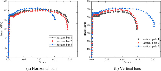
According to reference33, the material test specimens of all the specimens can be designed according to unified specifications, and the detailed dimensions of the horizontal bar and the vertical bar specimens are shown in Fig. 2. The tensile test of the material was carried out by a universal testing machine. The displacement variation was collected by an extensometer connected to the testing machine, and the collected test results are shown in Fig. 3. The parallel test results of each type of specimen are shown in Table 1. Finally, the average value of the sampling test is taken as the final result of each specimen.
Fig. 2.

Material test specimens.
Fig. 3.
Stress‒strain curves.
Table 1.
Results of the material test.
| Specimens | Tensile strength (MPa) | Yield strength (MPa) | Elastic modulus (MPa) | Elongation (%) | |
|---|---|---|---|---|---|
| Horizontal bars | H1 | 572.31 | 496.78 | 2.05 × 10⁵ | 19.24 |
| H2 | 583.65 | 517.76 | 2.05 × 10⁵ | 20.76 | |
| H3 | 601.45 | 532.47 | 2.05 × 10⁵ | 20.38 | |
| Average value | 585.80 | 515.67 | 2.05 × 10⁵ | 20.13 | |
| Vertical bars | V1 | 497.25 | 461.03 | 2.10 × 10⁵ | 16.34 |
| V2 | 520.94 | 445.12 | 2.10 × 10⁵ | 18.61 | |
| V3 | 510.87 | 440.70 | 2.10 × 10⁵ | 17.46 | |
| Average value | 509.69 | 448.95 | 2.10 × 10⁵ | 17.47 | |
Specimen design
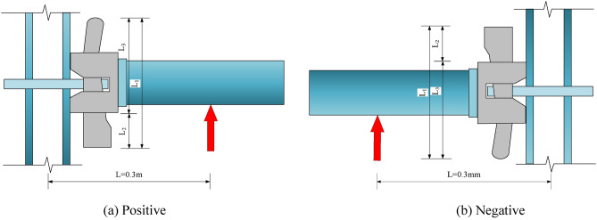
The components used in the test were all from the construction site. Due to errors in the processing and manufacturing process of the members, there are certain differences in the size of the components, resulting in differences in the structural forms of each group of test nodes. The specific differences are reflected in the depth of the bolt inserted into the connecting plate, the thickness of the bolt and the thickness of the connecting plate. The size diagram of the positive and negative test bolt insertion states is shown in Fig. 4. The detailed dimensions of the insertion depth of the pin into the connecting disc, the thickness of the pin and the thickness of the connecting disc are shown in Table 2. The bending state of the joint includes positive bending and negative bending. To study the positive and negative bending performances in detail, four groups of positive and negative bending parallel tests were carried out. When the joint is in the positive bending state, it is positive (J1-J4), and when the joint is in the negative bending state, it is negative (J5-J8).
Fig. 4.
Size diagram of the specimen after installation.
Table 2.
Characteristic parameters of each specimen (mm).
| Specimen number | L2 | L1 | L3 | t | b |
|---|---|---|---|---|---|
| J1 | 34 | 128 | 94 | 9.86 | 5.78 |
| J2 | 30 | 128 | 98 | 9.88 | 5.76 |
| J3 | 38 | 128 | 90 | 10.00 | 5.68 |
| J4 | 34 | 128 | 94 | 9.68 | 5.76 |
| J5 | 35 | 128 | 93 | 9.84 | 5.73 |
| J6 | 37 | 128 | 91 | 9.84 | 5.82 |
| J7 | 32 | 128 | 96 | 9.88 | 5.77 |
| J8 | 31 | 128 | 97 | 9.91 | 5.72 |
The thickness of the bolt is indicated by the letter ' b', and the thickness of the connecting plate is indicated by the letter ' t'.
Loading device and loading system
The test loading device is shown in Fig. 5. The vertical bending parallel test is carried out on the connection node of the plate-type formwork support through the reaction frame and the loading mold. The upper and lower ends of the node are fixed to the reaction frame through the loading mold to avoid relative slipping of the node during the loading process. The external force required for loading the specimen is provided by a 5-ton mechanical jack. The mechanical jack is connected to the tension and pressure sensor, the tension and pressure sensor is connected to the data acquisition instrument, the data acquisition instrument is connected to the computer, and the data acquisition is carried out by the computer. Because the wedge tightness of the bolt and the connecting plate during the installation of the formwork support may have an impact on the bending resistance of the joint, the horizontal bar bolt should be hammered to the same position as possible during the installation of the specimen.
Fig. 5.
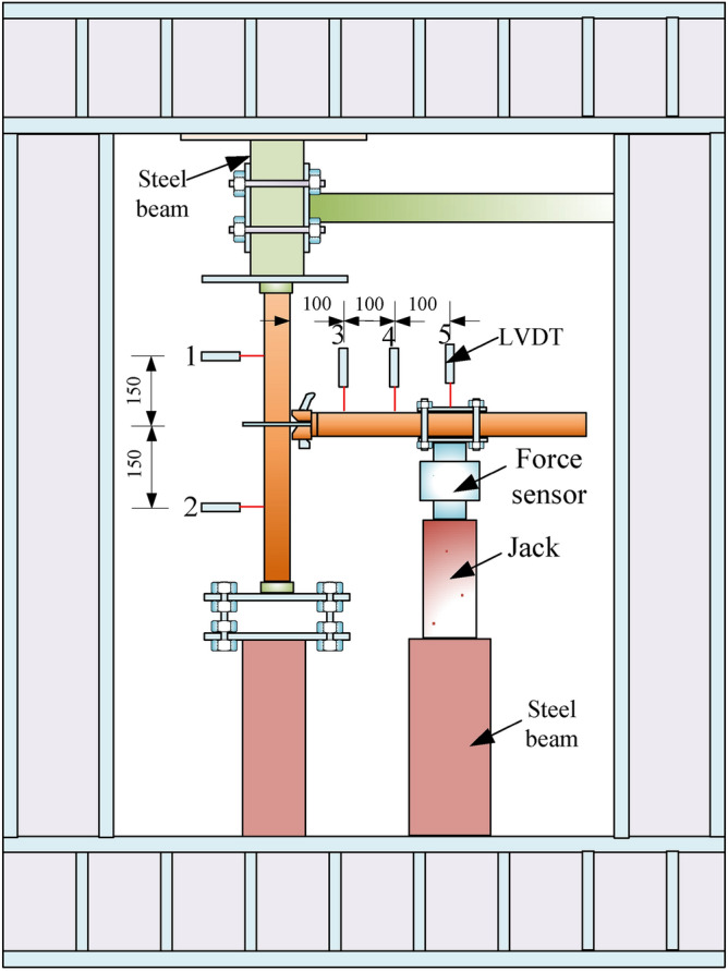
Loading device.
Before formal loading, the scaffold was preloaded. According to the finite element simulation, the preload is applied according to 20% of the yield load of the member, namely, 0.12 kN. The preload can check whether the loading equipment can work normally. After the preloading is completed, formal loading is carried out, and the loading of each stage is 1/10 ~ 1/15 of the estimated ultimate load. Due to the great reference significance of the rotational stiffness of the nodes in the initial stage, the loading of each stage is 0.1 kN at the initial loading, and the loading of each stage is 2 min. When the design load is approximately 3.5 kN (obtained by preliminary simulation), the loading is changed to 0.2 kN per stage. Finally, when the horizontal bar has a large rotation angle relative to the vertical bar and the load no longer increases, the displacement gradually increases, and it can be considered that the specimen node reaches the ultimate failure state.
Test measurement content
(1) Displacement measuring point arrangement
Five displacement sensors with a measurement accuracy of 0.01 mm were used to measure the displacement of the horizontal bar and the vertical bar during the loading process. The specific arrangement of the measuring points is shown in Fig. 5.
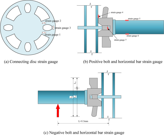
(2) Strain gauge
A total of 7 strain gauges were used in this test. Due to the different loading directions of the nodes, the positions of strain gauges 4 and 7 should be changed accordingly. The specific positions of the strain measuring points are shown in Fig. 6.
Fig. 6.
Strain gauge measuring points.
Analysis of test results
Test phenomena and failure modes
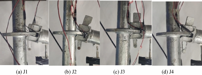
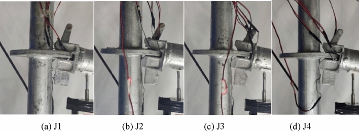
The failure mode of the connection joint of the disc-type formwork support under the action of the positive bending moment is shown in Fig. 7. At the beginning of the test, there was no obvious deformation of the specimen because the stiffness of the joint was relatively large at the beginning of loading. With the continuous increase in the bending moment of the joint, the rotational stiffness of the joint begins to decrease. When the bending moment reaches a peak, the displacement increases sharply when the bending moment increases little. At this time, joint buckling failure occurs, and the bolt and its components do not break. At this time, the upper part of the bolt is separated from the contact part of the vertical rod, and the horizontal rod has a large rotation angle relative to the vertical rod. It can be approximately considered that the joint has entered the bending limit state.
Fig. 7.
Positive bending failure mode.
The failure mode of the connection joint of the disc-type formwork support under the action of the negative bending moment is shown in Fig. 8. The overall failure mode is similar to the failure mode of the bolted scaffold connection node under the action of a positive bending moment.
Fig. 8.
Negative bending failure mode.
Analysis of the bending capacity
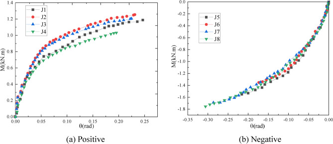
The moment-rotation curve corresponding to each specimen is shown in Fig. 12. The positive flexural bearing capacity is approximately 1.0–1.4 kN·m bending moment, and the negative flexural bearing capacity is approximately 1.6–1.8 kN·m bending moment. The positive and negative flexural bearing capacities are almost the same, and the negative flexural bearing capacity is slightly larger than the positive flexural bearing capacity.
Fig. 12.
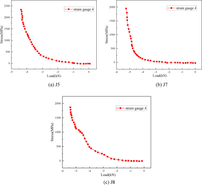
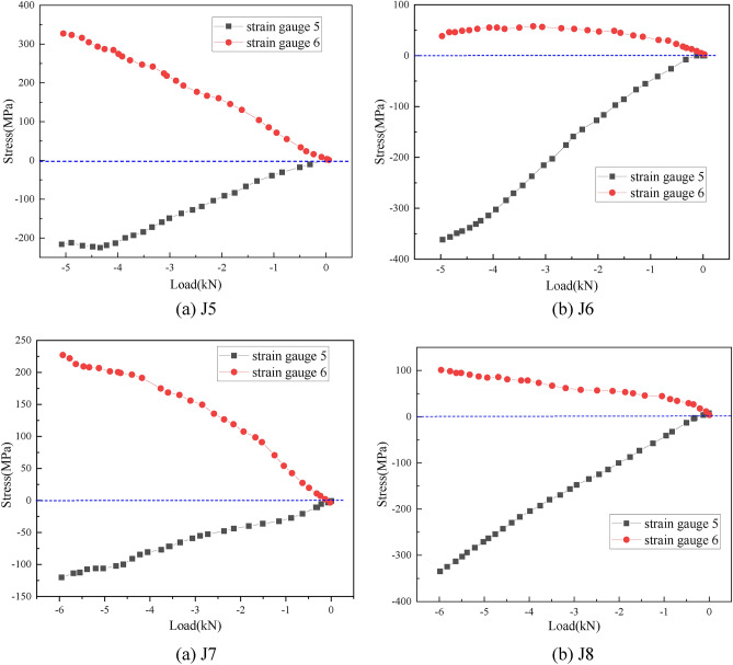
Stress–load curves of the vertical pole strain measuring points in the negative direction.
It can be found from Fig. 9a that although J1 and J4 have the same insertion depth, the bearing capacity of J1 is larger than that of J4 because the thickness of the connecting plate of J1 is larger than that of J4. The bearing capacity of J2 is higher than that of J1 and J4. The main reason is that the insertion depth of J2 is greater than that of J1 and J4. J2 and J1 have basically the same thickness of the connecting disc and the thickness of the pin. Although J3 has a connecting plate thickness greater than J2, its pin insertion depth is less than J2, resulting in a bearing capacity less than J2.Thus, it can be found that the ultimate bearing capacity of the joint is greatly affected by the insertion depth of the pin and the thickness of the connecting plate.
Fig. 9.
Moment–rotation curves obtained by experiments.
It is found from Fig. 9b that J7 and J8 have basically the same insertion depth of the bolt, but the thickness of the connecting plate of J8 is larger than that of J7, so its bearing capacity is slightly higher than that of J7.Since the insertion depth of J5 and J6 is smaller than that of J7 and J8, and the thickness of the connecting plate is also smaller than that of J7 and J8, the bearing capacity of all J5 and J6 is smaller than that of J7 and J8.Comparing J5 and J6, it can be found that because the insertion depth of J6 is smaller than that of J5, its bearing capacity is smaller than that of J6.It can also be found that the bearing capacity of the joint is also related to the insertion depth of the bolt and the thickness of the connecting plate under negative loading.
Stress analysis
The stress distribution of the connecting plate position
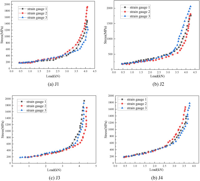
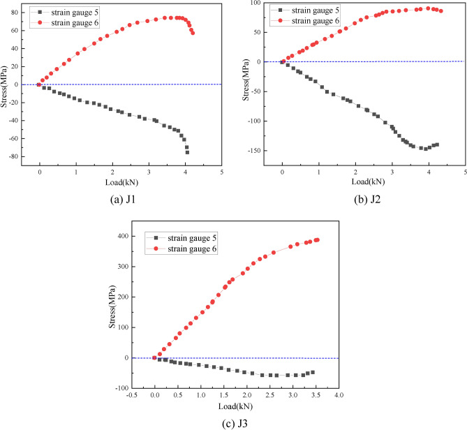
For the positive bending moment, the stress‒load curves of the three strain gauges at the position of the connecting plate are shown in Fig. 10. For the J4 test, strain gauge 3 is invalid, and the strain gauges of the other groups in the positive test are valid. It can be seen from Fig. 13 that in the initial stage of loading, as the load increases, the stresses at the three positions on the connecting plate are almost the same. As the load continues to increase, the stress of the three strain measuring points at the position of the connecting plate will be different, but the overall difference is not large. The stress distribution is very uniform, indicating that the joint is in a positive bending state. The stress difference between the tensile zone of the bending surface and the tensile zone of the nonbending surface is not large.
Fig. 10.
Stress–load curves of the disk-plate strain measuring points in the positive direction.
Fig. 13.
Load curves of the horizontal bar strain measuring points in the positive direction.
By comparing the above results, it can be found that when the node is in the positive bending state, the stress state on the connecting plate shows a relatively uniform development trend, and the overall stress is greater. When the node is in the negative bending state, the stress state on the connecting plate shows an uneven development trend. The stress in the tension zone of the bending surface is lower, but the stress in the tension zone of the nonbending surface is greater, indicating that for the positive bending state, the force capacity of the connecting plate generally has greater requirements for the negative bending state. Higher requirements are put forward for the force capacity of the bolt insertion position of the connecting plate.
(2) Stress distribution at the buckling position of the pole
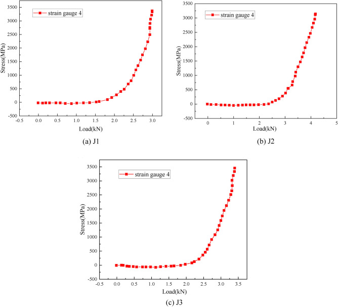
For the positive bending moment, the stress-load curve of the strain gauge measuring point at the buckling position of the vertical bar is shown in Fig. 11. The strain gauges of the corresponding measuring points in the J3 test failed, and the other groups of test data were complete. As shown in Fig. 14, at the initial stage of loading, with increasing load, the buckling position on the vertical rod shows a small degree of compression. As the load continues to increase, the buckling position on the vertical rod shows a tensile state, and the growth rate is very fast. Finally, when the node reaches the ultimate state of flexural bearing capacity, the stress on the vertical rod also reaches a higher level, which is higher than the tensile stress on the connecting plate.
Fig. 11.
Stress–load curves of the vertical pole strain measuring points in the positive direction.
Fig. 14.
Stress–load curves of the horizontal bar strain measuring points in the negative direction.
For the negative bending moment, the stress-load curve of the strain gauge measuring point at the buckling position of the vertical bar is shown in Fig. 12. The strain gauges of the corresponding measuring points in the J6 test were invalid, and the other groups of test data were complete. As shown in Fig. 12, at the initial stage of loading, with increasing load, the buckling position on the vertical rod shows a small degree of compression. As the load continues to increase, the buckling position on the pole shows a tensile state, and the growth rate is very fast. Finally, when the node reaches the ultimate state of flexural capacity, the stress on the pole also reaches a higher level, which is not much different from the tensile stress on the connecting plate. Compared with the positive stress state, when the joint is in the negative bending state, the stress at the buckling position on the vertical bar is only 2/3 of that on the vertical bar, indicating that when the joint is in the positive bending state, the buckling performance of the vertical bar is greater.
(3) Stress distribution of the buckling position of the horizontal bar
For the positive bending moment, the stress-load curve of the strain gauge measuring point at the buckling position of the horizontal bar is shown in Fig. 13. The strain gauges of the corresponding measuring points in the J3 test were invalid, and the other groups of test data were complete. For the position of the strain gauge measuring point on the horizontal bar of the J1 test, the distances from the nodes of the J2 and J4 tests are relatively close. As shown in Fig. 13, the tensile and compressive stress values on the horizontal bar of the J1 test are relatively close, and the tensile and compressive stress values on the horizontal bar of the J2 and J4 tests are quite different, indicating that the position slightly farther from the node is more prone to the difference between tension and compression, and this change is not regular.
For the negative bending moment, the stress-load curve of the strain gauge measuring point at the buckling position of the horizontal bar is shown in Fig. 14. For all the negative test horizontal bars, the distance between the strain gauge measuring point position and the node is not much different. As shown in Fig. 14, the distance between the tensile and compressive stress measuring points on the horizontal bars of the J5 and J7 tests is not much different. The distances between the tensile and compressive stress measuring points on the horizontal bars in the J6 and J8 tests are quite different. When the node is in a negative bending state, the symmetry of the stress of the tensile and compressive states on the horizontal bar is related to the symmetry of the distance from the node and has nothing to do with the distance from the node.
Characteristics of semirigid joints
When the connection section of the horizontal rod and the vertical rod of the formwork support is the full section of the horizontal rod, it is a rigid connection. When the connection section of the horizontal bar and the vertical bar gradually decreases, the inertia moment of the connection section gradually decreases, and the ability of the connection node to transmit the bending moment will decrease. Therefore, how much the bending moment at the end of the horizontal bar can be transmitted to the vertical bar depends on the section inertia moment of the connection node of the horizontal bar and the vertical bar. Starting from the rigid connection of the full section connection, the moment of inertia of the horizontal bar and the vertical bar connection section is gradually reduced. When it is reduced to a certain value, the critical state of the rigid and semi-rigid connection is reached. When it continues to decrease, the critical state of the semi-rigid and flexible connection will be found. Thus, the semi-rigid criterion of the socket node is obtained as shown in Fig. 15.
 |
Fig. 15.
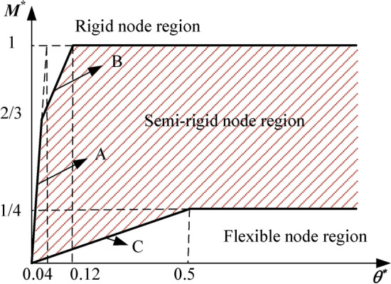
Semi-rigid judgment criterion of socket joint.
For the disc-type formwork support component, the section size of the horizontal rod is R = 24 mm, and the wall thickness is t = 2.5 mm.According to the material test results, the yield strength of the horizontal rod is fy = 515.67 × 10⁶ Pa, and the elastic modulus E = 2.06 × 10¹¹ Pa. Therefore, Wpx = 3.8648 × 10⁶m3 can be calculated, and then Mp = 1551.5N·m, Mplb/EIb = 0.02436 rad can be obtained.
Through the above formula, the bending moment‒rotation curve obtained from the bending test of the joint can be nondimensionalized (Fig. 16) and plotted into a curve to divide the rigid area of the joint, as shown in Fig. 17.
Fig. 16.
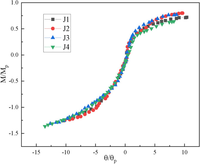
Dimensionless bending moment–rotation curves.
Fig. 17.
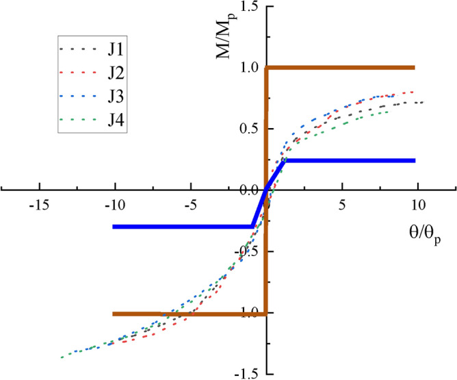
Rigid regions of the experimental joints.
The dimensionless bending moment‒rotation curve of the four groups of joints in the bending test of Fig. 16 shows that the plate-type formwork support connection joint is a typical semirigid connection joint. Whether the joint is in the positive bending state or the negative bending state, the bending moment‒rotation curve of the joint is in the middle of the semirigid joint area.
Finite element analysis
Finite element model establishment
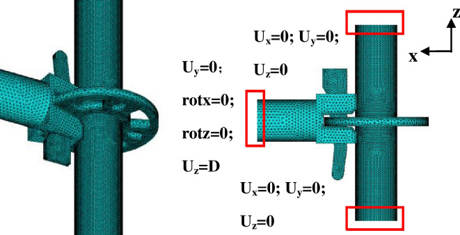
The finite element software ABAQUS is used to establish the three-dimensional solid model of the plate-type formwork support joint. The outer diameter of the horizontal rod is 48 mm, and the wall thickness is 2.5 mm. The outer diameter of the vertical rod is 48 mm, and the wall thickness is 3.2 mm. According to the material performance test results, the elastic modulus of the horizontal rod and the vertical rod material is 2.06 × 10⁵ N/mm2, the elastic modulus of the bolt and the connecting plate material is 1.95 × 10⁵ N/mm2, Poisson's ratio is 0.3, the friction coefficient is 0.2, and the normal stiffness is set to 1.0. Considering the irregularity of the model, the free mesh is used to mesh the nodes, and the mesh size is 2 mm. The finite element model is shown in Fig. 18.
Fig. 18.
Finite element model.
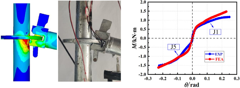
Figure 19 shows the comparison between the failure modes of the test and the finite element analysis. The comparison diagram shows that the finite element model can accurately predict the failure mode of the connection node of the disc-type formwork support.
Fig. 19.
The test results compared with the finite element results.
It can be found from Fig. 19 that the damage of the finite element calculation node is in good agreement with the test results, and the finite element model can accurately predict the bending stiffness and bending capacity of the forward joint.
Parametric analysis
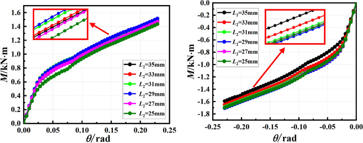
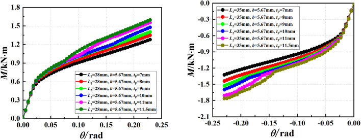
Through the experimental analysis, it can be known that the flexural capacity of the joint is related to the depth of the bolt inserted into the connecting plate and the thickness of the connecting plate. The buckling of the vertical bar is analyzed by parameterization of the influencing factors. The analysis results are shown in Figs. 20 and 21.
Fig. 20.
The influence of the insertion depth of the bolt on the mechanical properties of the joint.
Fig. 21.
The influence of different thickness of connecting plate on the mechanical properties of joints.
Through finite element analysis, it was found that the optimal depth for the insertion of the pin into the connecting disc was 29 mm. When the insertion depth of the pin exceeds 29 mm, the bearing capacity of the joint does not significantly improve. Regardless of whether the joint is in the positive or negative bending state.
Regardless of the positive and negative bending state of the joint, the thickness of the connecting plate has little effect on the initial stiffness of the joint, and has a significant effect on the bending capacity of the joint, especially on the ultimate bending capacity of the joint. With the increase of the thickness of the connecting plate, the ultimate bending capacity of the joint gradually increases, especially after the thickness of the connecting plate is greater than 10 mm, the bending capacity of the joint increases more obviously.
Conclusion
Through the parallel test of positive and negative bending resistance of the plate-type formwork support joints, the failure mode, stress distribution law and bending resistance of the plate-type formwork support joints are systematically studied, and the connection characteristics of the plate-type formwork support joints are verified to be semi-rigid connections.
The positive and negative bending bearing capacities are not very different, and the negative bending bearing capacity is slightly greater than the positive bending bearing capacity. The connection joint of the plate-type formwork support is a typical semirigid connection joint.
The test results show that the depth of the bolt insertion and the connection disc have a great influence on the bearing capacity of the joint regardless of the positive loading or negative loading.
The depth of the bolt inserted into the connecting disc is not the deeper the better. When the depth exceeds a certain value, the flexural bearing capacity of the joint will decrease instead.
The thickness of the connecting disc has little effect on the stiffness of the joint, but has a great influence on the bearing capacity of the joint under positive and negative loads. The bearing capacity increases with the increase of the thickness of the disc.
Acknowledgements
The Scientific Research Fund Project of China Construction Sixth Engineering (YKJ201928) and the Science and Technology Planning Project of the Ministry of Housing and Urban Rural Development (2019-K-165)
Author contributions
Guangjun Cheng . Writing – original draft,Data curation, Funding acquisition, Kun Han, Lei Wang and Ye Cheng .Experimental operation, data processing, proofreading. All authors have read and agreed to the published version of the manuscript.
Data availability
Data cannot be shared openly but are available on request from correspondence author.
Declarations
Competing interests
The authors declare no competing interests.
Footnotes
Publisher's note
Springer Nature remains neutral with regard to jurisdictional claims in published maps and institutional affiliations.
References
- 1.Yu, W. K., Chung, K. F. & Chan, S. L. Structural instability of multistory door-type modular steel scaffolds. Eng. Struct.26, 867–881 (2004). [Google Scholar]
- 2.Liu, H. B. et al. Structural performance and design method of new mortise–tenon full steel-tube scaffold. Adv. Steel Constr.14(02), 291–307 (2018). [Google Scholar]
- 3.Safety technical specification for socket type disc buckle steel pipe support in building construction, JGJ231–2010. China Building Industry Press, Beijing, (2010).
- 4.Technical standard for safety of disk lock steel tubular scaffold in construction JGJ/T231–2021. China Building Industry Press, Beijing, (2021).
- 5.Luo, Y. Z. et al. Classification and stability analysis on temporary support structures in construction. J. Build. Struct.37(4), 143–150 (2016). [Google Scholar]
- 6.Sevim, B., Bekiroglu, S. & Arslan, G. Experimental evaluation of tie bar effects on structural behavior of suspended scaffolding systems. Adv. Steel Constr.13(01), 62–77 (2017). [Google Scholar]
- 7.Zhao, Z. W. et al. Buckling capacity of socket-template scaffold system without X-bracing. J. Perform. Constr. Facil.34(01), 04019089 (2020). [Google Scholar]
- 8.Rezaiee-Pajand, M., Shahabian, F. & Bambaeechee, M. Buckling analysis of semi-rigid gabled frames. Struct. Eng. Mech.55(03), 605–638 (2015). [Google Scholar]
- 9.Ding, K. W. & He, X. P. Force mechanism and progressive collapse of steel tube-coupler scafford under local load. KSCE J. Civ. Eng.22(07), 2344–2353 (2018). [Google Scholar]
- 10.Huang, Y. L. et al. A monitoring method for scaffold-frame shoring systems for elevated concrete formwork. Comput. Struct.78(5), 681–690 (2000). [Google Scholar]
- 11.Chen, Z. H. & Zhao, Z. W. Analysis of door-type modular steel scaffolds based on a novel numerical method. Adv. Steel Constr.12(03), 316–327 (2016). [Google Scholar]
- 12.Zhao, Z. W. et al. Influence of random geometrical imperfection on stability of single-layer reticulated domes with semi-rigid connection. Adv. Steel Constr.15(01), 93–99 (2019). [Google Scholar]
- 13.Peng, J. L. et al. Stability study on scaffolds with inclined surfaces and extended jack bases in construction. Adv. Steel Constr.17(01), 73–83 (2021). [Google Scholar]
- 14.Zhao, Z. W. et al. Simplified numerical method for latticed shells that considers member geometric imperfection and semi-rigid joints. Adv. Struct. Eng.19(04), 689–702 (2016). [Google Scholar]
- 15.Zhao, Z. W. et al. The strong coupled form-finding and optimization algorithm for optimization of reticulated structures. Adv. Eng. Softw.140, 102765 (2020). [Google Scholar]
- 16.Peng, J. L. et al. Analytical and experimental bearing capacities of system scaffolds. J. Zhejiang Univ. Sci. A10(1), 82–92 (2009). [Google Scholar]
- 17.Chan, S. L. & Zhou, Z. H. A. Pointwise equilibrium polynomial (PEP) element for nonlinear analysis of frame. J. Struct. Eng.120(6), 1703–1717 (1994). [Google Scholar]
- 18.Chan, S. L., Huang, H. Y. & Fang, L. X. Advanced analysis of imperfect portal frames with semirigid base connections. J. Eng. Mech.131, 633–640 (2005). [Google Scholar]
- 19.Yu, W. K. An investigation into structural behavior of modular steel scaffolds. Steel Compos. Struct.4(3), 211–226 (2004). [Google Scholar]
- 20.Yu, W. K., Chung, K. F. & Chan, S. L. Structural instability of multistory door-type modular steel scaffolds. Eng. Struct.26(7), 867–881 (2004). [Google Scholar]
- 21.Lightfoot, E. & Oliveto, G. Collapse strength of tubular steel scaffold assemblies. Proc. Inst. Civ. Eng. Part 1- Des. Constr.63(2), 311–329 (1977). [Google Scholar]
- 22.Holmes, M. & Hindson, D. Structural behavior of load bearing false work. Proc. Inst. Civ. Eng. Part1- Des. Constr.67(2), 300–309 (1979). [Google Scholar]
- 23.Chen, A. C. Y., Guo, Z. X. & Wu, L. Experimental study on the mechanical properties of the steel tubular support frame structure. Ind. Constr.44(10), 140–145 (2014) ((In Chinese)). [Google Scholar]
- 24.Hu Q B. Study on mechanical properties of bolted scaffold platform. Dalian University of Technology, 2011. (In Chinese)
- 25.Liu, H. B. et al. Experimental and theoretical studies on the stability of steel tube-coupler scaffolds with different connection joints. Eng. Struct.106, 80–95 (2016). [Google Scholar]
- 26.Chu, A. Y. T., Chan, S. L. & Chung, K. F. Stability of modular steel scaffolding systems–theory and verification. Adv. Build. Technol.1, 621–628 (2002). [Google Scholar]
- 27.Guo Y. Study on bearing capacity of socket-type steel pipe formwork support frame. Xi 'an University of Architecture and Technology, 2014. (In Chinese)
- 28.Xu C. Study on the overall bearing capacity of the socket-type disc-type superthick formwork support system. Chongqing University, 2015. (In Chinese)
- 29.Technical Specification for Temporary Support Structures in Building Construction: JGJ 300–2013. Beijing: China Construction Industry Press, 2013. (In Chinese)
- 30.Buonopane, S. G. & Shafer, B. W. Reliability of steel frames designed with advanced analysis. J. Struct. Eng. ASCE132(2), 267–276 (2006). [Google Scholar]
- 31.Du, R. J. Key points of design calculation and construction management of scaffold and support engineering safety (7). Constr. Technol.46(02), 129–132 (2017) ((In Chinese)). [Google Scholar]
- 32.Du, R. J. Scientific specification for design and calculation of scaffold construction supports (6). Constr. Technol.39(06), 127–130 (2010) ((In Chinese)). [Google Scholar]
- 33.Tensile test of metallic materials, Part 1: Room temperature test method: GB/T 228.1–2010. Beijing: China Standard Press, 2010.
Associated Data
This section collects any data citations, data availability statements, or supplementary materials included in this article.
Data Availability Statement
Data cannot be shared openly but are available on request from correspondence author.


