Abstract
Based on the Hohai model, a creep constitutive model of viscoelastic-plastic soft rock with joint fracture damage is proposed to solve the rheological failure problem in soft rock tunnels surrounding rock. Based on the proposed creep model of rock with joint damage and the current analytical analysis method of circular tunnel, the analytical formulas of viscoelastic-viscoplastic stress and displacement of circular tunnel with joint damage surrounding rock are derived. ABAQUS finite element software is used to simulate the excavation of surrounding rock with different joint angles. The numerical solution is compared with the analytical solution to verify the accuracy of the theoretical formula. The results show that when the joint inclination is 45°, the displacement values of the two are 16.36 mm and 16.87 mm respectively. The error of the two is 3.02%. The theoretical calculation is in good agreement with the numerical simulation results, verifying the rationality of the derived analytical formula of viscoelastic-viscoplastic stress and displacement of soft rock tunnel with joint damage.
Keywords: Soft rock, Joint damage, Improved Hohai model, Plastic zone, UMAT subroutine
Subject terms: Natural hazards, Mathematics and computing
Introduction
The joints in rock masses are common geological structure, which is an important factor affecting rock stability. The presence of joints affects the deformation characteristics, stress changes, and integrity of tunnel surrounding rock more complex.1–3 When a tunnel passes through weak surrounding rock with developed joints, it is highly prone to engineering disasters such as the large deformation of the surrounding rock, deformation and distortion of the steel frame, and cracking of the secondary lining.4 The existence of joints greatly reduces the strength of rock masses, and the factors affecting the strength of jointed rock masses are often related to factors such as joint inclination angle, joint spacing, penetration rate, and joint roughness.5 The existence of joints makes the creep characteristics of rock masses more complex. How to define joint damage considering the primary joint, load-bearing joint and their mutual influence, which requires further research on the influence of joint damage on the stability of surrounding rock.
The creep effect of rock mass is an important cause of time-dependent deformation and even instability failure in tunnel engineering, mining engineering and slope engineering.6–8 It is crucial to establish a creep model that can describe the creep characteristics of rock mass throughout the entire process.9 The scholars have conducted research in this field and achieved a series of results in the viscoelastic plastic rheological constitutive model of rock masses. Steipi et al. described the viscoplastic parameters in the Nishihara model as a function of viscoplastic strain and proposed an improved Nishihara model.10 Gao et al. proposed a nonlinear rheological model that considers the effects of temperature and humidity.11 Xia et al. analyzed a unified rheological model containing four basic rheological elements.12,13 Although significant progress has been made in research,14,15 there are still some shortcomings. For example, most of the current creep constitutive models only study the complete rock mass, and the influence of the structural plane existing in the rock mass is not taken into account. Moreover, the built models are not suitable for simulating the failure process of the rock mass joint plane.
For tunnel engineering, the primary concerning issue is the stability of the surrounding rock after tunnel excavation. When analyzing the stability of jointed rock tunnels, the focus is usually on the displacement, stress, size and distribution of plastic zones in the surrounding rock. Therefore, scholars have conducted in-depth research on the plastic zone of tunnel surrounding rock in combination with engineering background. Jing et al. derived the boundary equation of the plastic zone of surrounding rock under non-uniform field based on the Drucker-Prager criterion, converted the equivalent radius of non circular section tunnels, analyzed the shape of the plastic zone under different lateral pressure coefficients, and used the single factor method to analyze the influencing factors of the plastic zone under different DP criteria.16 Taking Hualian high-speed Dongmachang No. 1 tunnel as an example, Nie et al. derived the invisible equation of the plastic zone radius of circular tunnel under non-isobaric conditions based on the Hoek–Brown strength criterion. The plastic zone radius was calculated using MATLAB mathematical software. Numerical simulations were conducted using FLAC3D finite difference software for comparative verification.17 Chen et al. introduced the nonlinear strength characteristics of rocks and established a logarithmic strain equation for the surrounding rock of deep buried tunnels. Considering the strain hardening characteristics of rocks, they proposed a finite strain analysis method based on the unified strain hardening strain softening and nonlinear shear dilation model for elastic–plastic coupling of surrounding rock.18 Bour et al. conducted a theoretical analysis on the stress distribution of the surrounding rock considering strain softening based on the variation law of the cohesive force of the borehole surrounding rock, and determined the theoretical formula for the plastic zone radius.19 So far, scholars have made significant achievements in the theoretical research of the plastic zone of surrounding rocks,20–22 but there are still some shortcomings: Firstly, a large number of studies only focus on solving the range of the plastic zone of the intact rock mass, and few studies have been done on the rock mass with joint cracks. The stress and displacement in the plastic zone of the tunnel have complicated changes with the joint dip angle, so further studies are needed. Secondly, when constructing the creep constitutive equation of rock mass, the joint damage characteristics of the rock mass are ignored, and only the classical constitutive model is used to solve the stress and displacement in the plastic zone of the tunnel. Its rationality needs to be discussed.
Therefore, building upon the current analytical method for circular tunnels, this study posits that the constitutive relationship of the surrounding rock adheres to the creep constitutive model of jointed damage rock. The analytical formulas for the viscoelastic plastic stress and displacement of circular tunnels containing jointed damage surrounding rock are derived and solved. The ABAQUS finite element analysis software is used for numerical simulation. The numerical solution is compared with the analytical solution to verify the accuracy of the theoretical formula calculation.
Derivation of viscoelastic plastic analytical formula for circular tunnels
Basic assumptions
Definition of joint damage variables
Assuming  represent the total number of joint damage elements, the original joint damage, the damage generated after being loaded, the damage caused by the interaction between the joint and the load, and the undamaged part, respectively.
The initial joint damage  is represented as the proportion of primary joint damage to total damage.
 |
1 |
After being subjected to a load, if the joint expands or new joints are formed, the damage variable  of the jointed rock mass under load is defined as
 |
2 |
In summary, the total damage variable  of the jointed rock mass under load can be defined based on the final degree of damage to the rock mass,
 |
3 |
Substituting Eqs. (1) and (2) into Eq. (3) yields the relationship between primary joint damage, damage under load, and total damage,
 |
4 |
According to Eq. (4), it can be seen that after the jointed rock mass is subjected to external loads, the stress concentration in the joint area accelerates the damage and failure of the rock mass, and the weakening caused by the coupling of joints and loads can be represented by  .
.
The elastic modulus, as a key parameter describing the elastic deformation stage of materials, indirectly evaluates the initial damage degree  by effectively measuring the initial loss of jointed rock masses,
 |
5 |
where  represents the elastic modulus of rock masses with different joint angles.
Assuming that the strength of rock microelements follows the Weibull statistical distribution law, the variable of rock damage under load can be represented by Eq. (6).
 |
6 |
where  and
and  are statistical distribution parameters that are related to the mechanical properties of the material.
  is the statistical distribution variable of microelement strength.
 |
7 |
According to the generalized principle of strain equivalence, the initial damage inside the jointed rock mass is regarded as the first damage state, and the total damage generated by the combination of joint damage and load damage is regarded as the second damage state. Therefore, the damage constitutive relationship of the jointed rock mass can be expressed as
 |
8 |
In order to make the joint damage model more specific and reflect the characteristics of joint damage, the joint damage model components are proposed as shown in Fig. 1.
Fig. 1.

Schematic diagram of joint damage element model.
Creep constitutive model
Through comparison and discussion with reference,23 it is found that the Hohai model can better describe the instantaneous deformation, attenuation creep, steady-state creep elastic aftereffect, and relaxation properties of rocks during rheological behavior. However, it do not consider the influence of joint damage on rock strength. Therefore, the creep constitutive model containing joint damage is obtained by combining as shown in Fig. 2.
Fig. 2.
Schematic diagram of creep element model with joint damage, where  are the elastic modulus of the elastic element and Kelvin model element.
  are the stress of the elastic element, viscous element, and Kelvin model element.
  are the viscosity coefficient of the Kelvin model element and viscous element.
  is the joint damage.
The first part is joint damage elastic elements,
 |
9 |
The second part is about adhesive damage components,
 |
10 |
The third and fourth parts are all Kelvin model components,
 |
11 |
If the damage creep constitutive model satisfies the series parallel connection rule of the component rheological model, then
 |
12 |
When all components participate in the creep process, substituting Eqs. (9)–(11) into Eq. (12) yields the constitutive relationship for joint damage creep,
 |
13 |
In the early stage of creep, i.e., t = 0 and  the initial condition is
 |
14 |
Substitute Eq. (14) into Eqs. (9) and (11), and perform Laplace transform to obtain
 |
15 |
The joint damage creep constitutive model obtained by performing inverse Laplace transform on Eq. (15) when t = 0 and 
 |
16 |
When  , By combining Eqs. (9–14), it can be concluded that
 |
17 |
where  represents performing Laplace transform on
  , S represents the Laplacian variable.
The one-dimensional joint damage creep constitutive equation derived above is only applicable to uniaxial stress states. The physical component model is limited to representing the one-dimensional creep differential model. However, three-dimensional rheological models have complex stresses and it is difficult to express them using component models. Consequently, analogical methods are usually used to derive them from one-dimensional to three-dimensional.
According to the elastic–plastic theory, the stress tensor  can be decomposed into the spherical stress tensor
  and the deviatoric stress tensor
  .
.
 |
18 |
The spherical stress tensor and deviatoric stress tensor of rocks under conventional triaxial stress state ( ) are expressed as
 |
19 |
where  is the spherical strain tensor,
  is the deviatoric strain tensor.
Substituting Eq. (19) into Eq. (18) yields
 |
20 |
For the viscoplastic model, the creep equation under three-dimensional stress state is
 |
21 |
The constitutive equation of a nonlinear sticky pot model under three-dimensional stress state can be expressed as
 |
22 |
By analogy with the one-dimensional form of Eq. (17), Eqs. (20) and (21) are substituted into Eq. (17). and  in Eq. (17) is replaced by a constant deviatoric stress
  in rock tests. Finally, based on the superposition principle, the deviatoric strain tensor of the joint damage creep constitutive equation under three-dimensional stress state can be obtained as
 |
23 |
Because strain tensors can be decomposed into spherical strain tensors  and deviatoric strain tensors
  , substituting Eqs. (20) into (23) yields the total axial deformation of the rock,
 |
24 |
where  can be obtained. Therefore, the total rock strain under principal stress
  can be transformed from Eqs. (24) to (25),
 |
25 |
The total strain of the rock in the triaxial state is  , and considering that the rock is positively compressed and negatively tensioned, therefore
  is negative, Eq. (25) can be written as
 |
26 |
The relationship between elastic modulus  , bulk modulus
  , Poisson’s ratio
  , and shear modulus
  is shown in Eqs. (27) and (28).
 |
27 |
 |
28 |
When t = 0, the initial strain of the rock can be obtained according to Eqs. (26–28).
 |
29 |
By combining Eqs. (17), (18) and (23) with the concepts of stress tensor and strain tensor, the total deformation of three-dimensional joint damage creep can be obtained as
 |
30 |
Model parameters identification
In this study, the parameters of constitutive model are identified by the least square method, Levenberg–Marquardt algorithm and curve decomposition method. Parameter identification of the creep constitutive model of joint damage can be divided into two parts, namely, joint parameter identification and creep model parameter identification. The following text takes the joint dip angle of 45° as an example. The calculation formula for joint damage parameter P0 and a are as follows,
 |
31 |
 |
32 |
where  is lateral nominal stress.
  is the elastic modulus of intact rock.
  is the elastic modulus of rock mass with joint dip angle
  .
.  is the Poisson’s ratio of rock mass with joint dip angle
  .
.  is creep stress.
  is creep strain.
The identification of creep model parameters is divided into two stages, namely the the pre-accelerated creep stage and the accelerated creep stage. For the pre-accelerated creep stage of carbonaceous shale, the least squares method can be applied to Eq. (30) to determine the model parameters of the first three parts of the three-dimensional constitutive model, For the accelerated creep stage curve, nonlinear least squares method is used to Eq. (30) to first determine modulus of elasticity  , shear modulus
  ,
,  and
and  , coefficient of viscosity
  and
and  . Then the least squares method is used to fit the second part of the creep test curve, finally obtaining the nonlinear clay pot parameter
  . The fitting curve is shown in the Fig. 3. The fitting equation is listed in the Table 1.
Fig. 3.
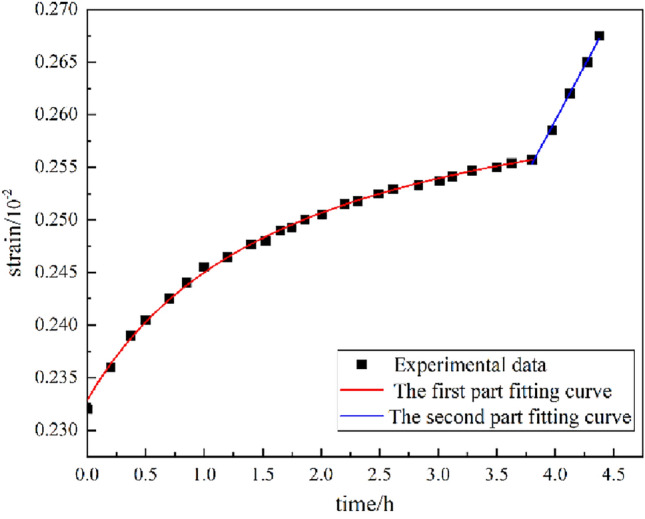
Rheological curve fitting diagram for parameter identification of carbonaceous slate.
Table 1.
Creep curve fitting equation.
| Curve | Fitting curve equation | R2 |
|---|---|---|
| Part I fitting curve equation |  |
0.9984 |
| Part II fitting curve equation |  |
0.9979 |
All parameters of the creep constitutive model for 45° joint fissures identified by parameter identification are shown in Table 2.
Table 2.
Parameters of joint damage creep model.
 
|
 
|
 
|
 
|
 
|
 
|
 
|
 |
 |
|---|---|---|---|---|---|---|---|---|
| 16.73 | 10.53 | 51.66 | 52.85 | 19.73 | 250.42 | 92.864 | 0.426 | 1586.54 |
Mechanical model
Because the longitudinal length of the circular cavity is much larger than the size of the transverse section, the mechanical analysis of the circular cavity structure can be simplified to the plane strain problem. Due to the complex and changeable conditions of surrounding rock in practical engineering, it is necessary to simplify the theoretical analysis. The surrounding rock material is regarded as an ideal viscoelastic-plastic material. The following assumptions are made.
The surrounding rock is considered a continuous, homogeneous and isotropic medium.
Within the range of the plastic zone, the rock mass conforms to the Hoek Brown strength criterion.
The surrounding rock in the plastic zone after yielding complies with the flow law of rock volume expansion.
The small elastic deformation caused by stress redistribution in the yielding surrounding rock can be disregarded.
The support resistance is assumed to be uniformly distributed radially.
Based on the above assumption, the calculation diagram of the circular tunnel model is shown in Fig. 4. Where  is the range of the circular tunnel,
  is the range of the viscoplastic zone.
  is the original rock stress. When
  , it is the viscoplastic zone. When
  , it is the viscoelastic zone.
Fig. 4.
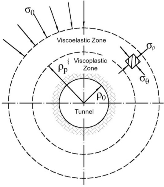
Calculation diagram of circular tunnel.
Stress solution in viscoelastic zone
In a polar coordinate system, its geometric equation is
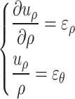 |
33 |
where  represents the radial displacement of the surrounding rock of the tunnel.
  is the radial strain
  of the surrounding rock of the cavern. The tangential strain of the surrounding rock of the tunnel.
According to the theory of linear elasticity, the static equilibrium equation for elastic problems is
 |
34 |
where  is the distance from any point around the cave to the center of the cave.
  is the radial stress in the surrounding strata of the cave.
  represents the tangential stress in the surrounding strata of the cave.
The boundary conditions of the viscoelastic zone are
 |
35 |
Due to the redistribution of surrounding rock stress caused by tunnel excavation, a secondary stress state develops. The radial stress of the surrounding rock tends to decrease from a distance to the center of the tunnel, and decreases to 0 at the tunnel wall. Considering that the radial stress of the surrounding rock is released when there is no support, the radial stress at any point in the surrounding rock can be expressed as
 |
36 |
where  is the stress release coefficient of the surrounding rock, which is related to the range of influence of the palm face.
According to the rock creep curve, its elastic strain  and creep strain
  together constitute the total strain of the viscoelastic zone
  , as shown in Eq. (37).
 |
37 |
For the creep constitutive plane strain problem considering joint damage, the elastic strain follows the generalized Hooke’s law. The radial and tangential elastic strains are shown in Eq. (38).
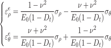 |
38 |
Assuming that creep only depends on the deviation part of the stress tensor and the volume is constant,24 the creep strain can be expressed as
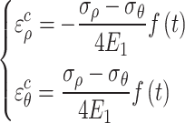 |
39 |
where  .
.
Therefore, the total strain of the surrounding rock before yielding can be represented by Eqs. (38) and (39) as
 |
40 |
According to the solution to the plane strain problem in the elastic zone proposed by Mitchell, combined with Eq. (36), the stress distribution solution of the surrounding rock in the viscoelastic zone can be obtained,
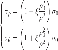 |
41 |
Solution of displacement in viscoelastic zone
Substituting Eq. (41) into Eq. (40) yields
 |
42 |
Simplification can be obtained,
 |
43 |
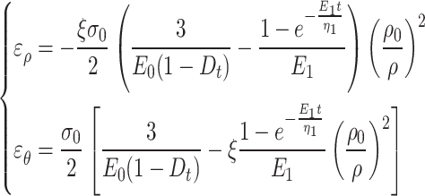
For the surrounding rock of a deeply buried tunnel in an isotropic and isobaric state, its Poisson’s ratio can be taken as 0.5. Therefore, the total viscoelastic strain in the viscoelastic zone of a circular tunnel is
 |
44 |
Stress solution in the viscoplastic zone
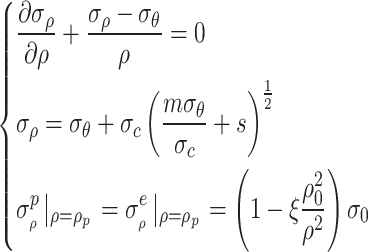
In the range of the viscoelastic plastic zone of a circular tunnel, when the boundary interface is the range of the plastic zone, i.e.  , the radial stress on the boundary interface of the viscoelastic plastic zone is equal. Combining the Hoek Brown criterion with the equilibrium equation, the following equation system is obtained,
 |
45 |
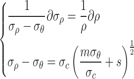
According to Eq. (45), it can be concluded that
 |
46 |
According to the third equation in Eq. (45),25 it can be concluded that
 |
47 |
By solving Eq. (47), the radial stress within the viscoplastic zone of a circular tunnel can be obtained as
 |
48 |
By substituting the radial stress within the viscoplastic zone into the Hoek Brown strength criterion, the tangential stress within the viscoplastic zone can be obtained,
 |
49 |
Solution of displacement in the viscoplastic zone
The strain of surrounding rock within the viscoplastic zone is composed of elastic strain  , creep strain
  and plastic strain
  , as shown in Eq. (50).
 |
50 |
According to the assumption (3), the flow rule of rock mass volume expansion is obtained by combining Eqs. (31) and (47),
 |
51 |
where  is the plastic expansion coefficient.
Since the elastic strain and creep strain of the surrounding rock do not occur volume strain before yielding, it can be obtained that
 |
52 |
Substituting Eq. (52) into Eq. (51) yields
 |
53 |
According to the creep constitutive Eq. (17) and the total strain Eq. (43) of the viscoelastic zone, the creep strain of the viscoplastic zone is
 |
54 |
For the model in this paper, it is assumed that the small deformation caused by stress redistribution has a weak influence on the elastic strain, so it can be ignored. At this time, the elastic strain in the viscoelastoplastic region has been completed, and it is considered that the elastic strain at the interface of the viscoelastic region and the viscoplastic region (i.e.  ) is equal. Therefore, it can be concluded that
 |
55 |
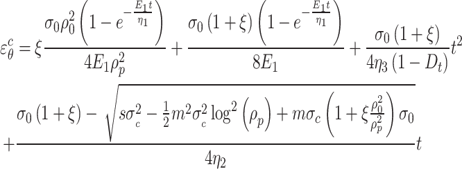
There is a positive proportional relationship between the principal stress difference and creep strain. In order to facilitate problem-solving, the average creep strain obtained from the difference between the creep strain outside the viscoelastic zone and the stress difference at the circular cavity wall is taken as an the approximate value for the creep strain of the surrounding rock in the viscoelastic zone.26
 |
56 |
For the interface between the viscoelastic zone and the viscoplastic zone, both radial displacement and tangential strain are equal. By integrating Eq. (53), the solution for the tangential strain in the viscoplastic zone can be obtained.
 |
57 |
where  . A is the solution for tangential strain in the viscoelastic region.
According to Eq. (56), the solution for radial strain in the viscoplastic zone is
 |
58 |
Calculation of plastic zone range
The radial stress in the plastic zone at the inner boundary of the surrounding rock is  , which conforms to the Hoek Brown strength criterion. It can be obtained by substituting it into the second equation of Eq. (45),
 |
59 |
where  is the stress release coefficient of the surrounding rock with a viscoelastic boundary. The circumferential stress
  is 0.
is 0.
For the surrounding rock within the plastic zone of a circular tunnel, the stress release coefficient  . When the stress release coefficient of the surrounding rock increases, the range of the plastic zone also correspondingly increases. The stress at the interface between the tunnel wall and surrounding rock is
  . By substituting the boundary conditions into the radial stress Eq. (48) in the viscous plastic zone, it can be obtained that
 |
60 |
where  is the stress release coefficient of the surrounding rock.
  is the excavation range of the tunnel.
  is the range of the viscoplastic zone.
  is the initial stress.
  is the compressive strength of rock. m and s are the parameters for the Hoek Brown strength criterion. Equation (60) contains only one unknown range of plastic zone of surrounding rock. So the range of plastic zone of circular tunnel can be obtained by solving this equation.
Example analysis
Numerical model construction
In order to verify the feasibility of the theoretical calculation, the analytical solution based on the formula in the paper is compared with the numerical simulation numerical solution. ABAQUS finite element software is used to simulate and analyze the excavation of surrounding rock with joint inclination angles of 0°, 30°, 45°, 60° and 90°, respectively. Taking the surrounding rock tunnel model with joint inclination angles of 0° and 45° as an example, numerical models are established as shown in Fig. 5. The length, width and height of the surrounding rock model are 80 m, 80 m and 10 m respectively, The width and height of the tunnel excavation are 12.5 m and 9.5 m. The distance between the bottom of the tunnel and the ground surface is 40 m. To better simulate joint damage, the joint thickness is 40 cm and the joint spacing is 4 m. The material properties used in the surrounding rock are the material constitutive relationships developed for the secondary development of the joint damage creep model established. The parameters of the joint creep model are listed in Table 3.
Fig. 5.
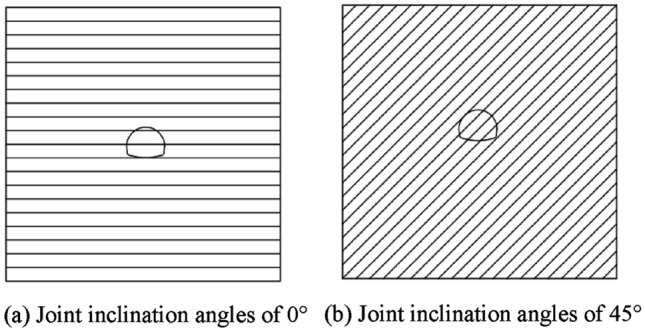
Numerical simulation diagram of surrounding rock tunnel.
Table 3.
Parameters of joint creep model.
| Joint inclination angle |
 /GPa /GPa |
 /GPa /GPa |
 /GPa /GPa |
 /GPa /GPa |
 /GPa·h /GPa·h |
 /GPa·h /GPa·h |
 /GPa·h /GPa·h |
 |
 |
R2 |
|---|---|---|---|---|---|---|---|---|---|---|
| 0° | 29.67 | 18.67 | 82.89 | 79.66 | 44.92 | 214.65 | 17.48 | 1.90 | 1046.17 | 0.9956 |
| 45° | 16.73 | 10.53 | 51.66 | 52.85 | 19.73 | 250.42 | 9.29 | 0.43 | 1586.54 | 0.9982 |
| 90° | 25.15 | 14.37 | 132.88 | 131.65 | 56.74 | 1090.00 | 36.95 | 1.54 | 1106.48 | 0.9931 |
Analysis of surrounding rock displacement
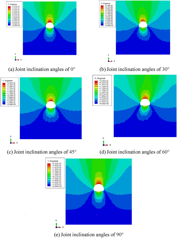
Figure 6 shows the displacement cloud maps of ABAQUS post-processing output joints with inclination angles of 0°, 30°, 45°, 60° and 90° during excavation of surrounding rock with different joint damage. From Fig. 5, it can be seen that joint damage causes a stepped change in the displacement of the surrounding rock. The displacement of the surrounding rock shows a layered and symmetrical arrangement with the depth of the surrounding rock, and gradually increases from the surface downwards. The inner surrounding rock of the tunnel is subjected to greater load and more severe compression displacement deformation due to the superposition of the self weight of the outer surrounding rock. At the top of the tunnel arch, the displacement reaches its maximum value, which is due to the weak support caused by tunnel excavation and the increased settlement of the arch; The displacement of the surrounding rock gradually decreases from the bottom of the inverted arch downwards. This is due to the redistribution of stress in the surrounding rock caused by tunnel excavation, and the surrounding rock around the tunnel compresses each other, resulting in uplift at the bottom of the inverted arch. Therefore, the displacement at the inverted arch is greater than that of the surrounding rock below it.
Fig. 6.
Displacement cloud map of surrounding rock with different joint angles.
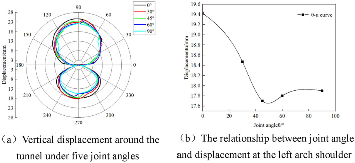
The the vertical displacement of surrounding rock with five different joint angles are plotted in Fig. 7a. According to Fig. 7a, it can be seen that the displacement of the surrounding rock around the tunnel gradually decreases with the increase of joint inclination angle. When the dip angle of the joint is 0°, the displacement of the surrounding rock around the tunnel reaches its maximum. When the dip angle of the joint is 45°, the displacement of the surrounding rock around the tunnel has a minimum value or a stable trend of change. Taking the left arch shoulder as an example, draw the relationship curve between joint angle and displacement as shown in Fig. 7b. As shown in Fig. 7b, when the joint angle is 0°, the displacement of the left arch shoulder of the surrounding rock reaches its maximum value of 19.43 mm. When the joint angle increases, the displacement sharply decreases, reaching a minimum value of 17.72 mm at a joint angle of 45°. Subsequently, the displacement slightly increases with the increase of the joint angle, and finally stabilizes at a joint angle of 90°, with a displacement value of 17.93 mm.
Fig. 7.
Effect of different joint damage on tunnel displacement.
Comparison of results
In order to verify the reliability of the joint damage rock creep constitutive model proposed in this paper, the analytical solution of plastic zone range of circular tunnels was compared with the numerical simulation solution. According to reference,27 the parameters m and s of the Hoek Brown criterion are determined. The remaining parameters are listed in Table 3. The range of the plastic zone with joint dip angles of 0°, 45° and 90° was calculated using the parameters of the joint damage creep model. The calculation results are listed in Table 4.
Table 4.
Calculation results of plastic zone range.
| Joint angle | 0° | 45° | 90° |
|---|---|---|---|
| Plastic zone range /m | 24.08 | 9.49 | 22.92 |
According to the calculation results of the plastic zone range, the displacement values of the corresponding positions of the model in the numerical simulation are extracted, and the numerical simulation results are obtained. The range of the plastic zone in Table 4 and the model parameters are substituted into Eqs. (44) and (56) respectively to calculate the theoretical values of plastic zone displacement.
From Table 4, it can be seen that as the dip angle of the joint increases, the range of the plastic zone shows a trend of first decreasing and then increasing. It is consistent with the study in reference.28 A small plastic range zone means that the stress on the surrounding rock of the tunnel is more concentrated. The support structure will bear greater pressure, which may cause local damage to the surrounding rock or premature damage or failure of the support structure, increasing the risk of tunnel collapse. Figure 8 shows the comparison between theoretical displacement values and numerical simulation results for the same plastic zone range. From Fig. 8, it can be seen that there is a negative correlation between displacement and joint inclination angle within the same plastic zone range. When the dip angle of the joint is 0°, the theoretical displacement value is 24.08 mm, the numerical simulation value is 22.31 mm, and the error between the two is 7.93%. When the dip angle of the joint is 45°, the displacement values of the two are 16.36 mm and 16.87 mm, respectively, with an error of 3.02%, which is relatively small. When the joint inclination angle is 90°, the theoretical displacement is 15.10 mm, and the numerical model displacement value is 14.48 mm, with an error of 4.28%. The results indicate that the established creep constitutive model with joint damage has good applicability.
Fig. 8.
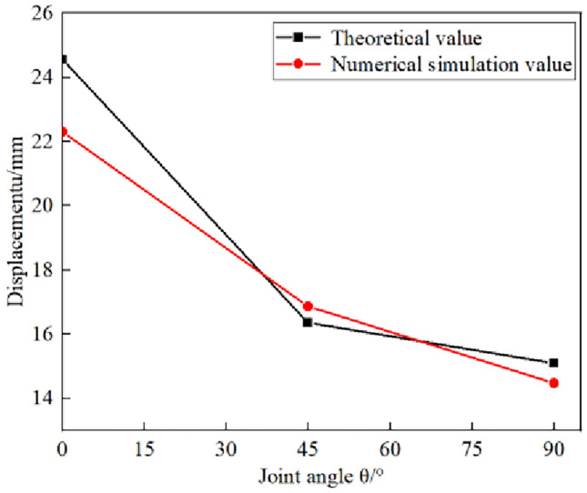
Comparison between theoretical values and numerical simulations.
Conclusion
This paper focuses on the creep constitutive plane strain problem of jointed damaged surrounding rock, and proposes a derivation and solution method for the analytical formulas of viscoelastic plastic stress and displacement in circular tunnels with jointed damaged surrounding rock. Based on the creep constitutive model of jointed damaged rock proposed in this article and the secondary development of UMAT subroutine, numerical simulation calculations of tunnel excavation are completed. The influence of different joint inclination angles on surrounding rock displacement is analyzed. The main conclusions are as follows:
On the basis of considering the damage of soft rock joints, the joint damage element model is reorganized with the improved Hohai model. A viscoelastic plastic creep constitutive model of soft rock containing joint crack damage is proposed. Based on the proposed constitutive model, combined with the generalized Hoek Brown strength criterion and the analytical method for circular tunnels, the viscoelastic viscoplastic stress and displacement calculation formulas for circular tunnels with joint damage surrounding rock are derived.
By embedding the creep constitutive model of joint damage surrounding rock into UMAT subroutine, ABAQUS finite element analysis software is used to numerically simulate the tunnel excavation of surrounding rock with joint inclination angles of 0°, 30°, 45°, 60° and 90°, respectively. It can be seen from the results that the displacement of surrounding rock presents a layered symmetrical arrangement with the depth of surrounding rock, and gradually increases from the surface down. When the joint inclination angle is 0°, the displacement of the left arch shoulder surrounding rock reaches the maximum value of 19.43 mm.
The analytical solution of the circular tunnel is compared with the numerical simulation results. When the joint inclination angle is 45°, the theoretical and analytical displacement values are are 16.36 mm and 16.87 mm, respectively. The error of both is 3.02%, which is the smallest error. When the joint inclination angle is 90°, the theoretical displacement is 15.1 mm, and the numerical model displacement value is 14.48 mm, with an error of 4.28%.
Acknowledgements
This research is supported by National Natural Science Foundation of China (NSFC Contract No. 52378388), the Fundamental Research Funds for the Central Universities, CHD (Program no. 300102213211, 300102214105), Research Funds for the Interdisciplinary Projects, CHU (Program no. 300104240912).
Author contributions
Taotao Hu, Peng Tu and Jianlong Liu wrote the main manuscript text. Yulong Zhao prepared figures. All authors reviewed the manuscript.
Data availability
The datasets generated and/or analysed during the current study are not publicly available due [The subject needs further research and is inconvenient to be disclosed] but are available from the corresponding author on reasonable request.
Declarations
Competing interests
The authors declare no competing interests.
Footnotes
Publisher’s note
Springer Nature remains neutral with regard to jurisdictional claims in published maps and institutional affiliations.
References
- 1.Lin, C. B. et al. Influence of three-dimensional persistent joints on surrounding rock stability of large-span tunnel. J. Central South Univ. Sci. Techno.54, 1141–1152 (2023). [Google Scholar]
- 2.Wang, J., Song, W. D. & Fu, J. X. A damage constitutive model and strength criterion of rock mass considering the dip angle of joints. Chin. J. Rock Mech. Eng.37, 2253–2263 (2018). [Google Scholar]
- 3.Wang, Z. B., Zhang, H. G., Zhang, Y. Y. & Zhang, L. J. Study on quality evaluation and supporting for surrounding rock of large section tunnel with abundant joint fissure. Chin. Energ. Env. Prot.45, 254–262 (2023). [Google Scholar]
- 4.Luo, S. L., Wu, R. B. & Zhang, Z. Q. The influence of joint inclination angle and set number on stability of railway tunnel surrounding rock. Railway Invest. Surv.49, 48–53 (2023). [Google Scholar]
- 5.Tao, Z. Y. Mechanism and Engineering Application of Fracture Evolution of Intermittent Joint Surrounding Rock in Deep Tunnels, Chin. Univ. Min. Techno., (2023).
- 6.Lin, H., Cao, P. & Fang, J. Q. Confirmation on reasonable timbering time for tunnel in rheological cases of III-rock mass. Disaster Adv.5, 220–225 (2012). [Google Scholar]
- 7.Sun, J. Rheology of geotechnical materials and their engineering applications. Chin. Archit.& Build. Press (1999).
- 8.Xiao, C., Zheng, H. C., Hou, X. L. & Zhang, X. J. A stability study of goaf based on mechanical properties degradation of rock caused by rheological and disturbing loads. Int. J. Rock Mech. Min.25, 741–747 (2015). [Google Scholar]
- 9.Hu, T. T., Kang, Z. B., Chen, J. X., Hu, X. & Wang, D. Non-constant viscoelastic-plastic creep model and finite elementanalysis based on interbedded rock mass. J. Chongqing Univ.46, 118–126 (2023). [Google Scholar]
- 10.Steipi, D. & Gioda, G. Visco-plastic behaviour around advancing tunnels in squeezing rock. Rock Mech. Rock Eng.42, 319–339 (2009). [Google Scholar]
- 11.Gao, Y. N., Gao, F., Zhang, Z. Z. & Zhang, T. Visco-elastic-plastic model of deep underground rock affected by temperature and humidity. Int. J. Min. Sci. Techno.20, 183–187 (2010). [Google Scholar]
- 12.Xia, C. C., Wang, X. D., Xu, C. B. & Zhang, C. S. Method to indentify rheological models by unified rheological model theory and case study. Chin. J. Rock Mech. Eng.27, 1594–1600 (2008). [Google Scholar]
- 13.Xia, C. C., Xu, C. B., Wang, X. D. & Zhang, C. S. Method for parameters determination with unified rheological mechanical model. Chin. J. Rock Mech. Eng.28, 425–432 (2009). [Google Scholar]
- 14.Yan, J. B., Kong, L. W. & Wang, J. T. Evolution law of small strain shear modulus of expansive soil: From a damage perspective. Eng. Geol.315, 107017 (2023). [Google Scholar]
- 15.Yan, J. B., Kong, L. W., Xiong, C. F. & Xu, G. F. Damage analysis of shear mechanical behavior of pile-structural soil interface considering shear rate effect. Acta Geotech.18, 5369–5383 (2023). [Google Scholar]
- 16.Jing, L. W., Zhang, S. X., Xiao, Q. H., Fang, X. & Jing, W. Analysis of influencing factors of roadway surrounding rock plastic zone based on Drafcker-Prager criterion. China Mingng Magazine32, 150–157 (2023). [Google Scholar]
- 17.Nie, J. C. et al. Distribution law of tunnel plastic zone and disturbed stress field under non-isobaric load. Railway Stand. Des.10.21203/rs.3.rs-4702596/v1 (2024). [Google Scholar]
- 18.Chen, J. J., Lu, Z. J., Meng, C., Hu, S. H. & Zhao, L. H. Finite strain solution for the surrounding rock of deeply buried tunnels based on the nonlinear strength characteristics. J. Railway Sci. Eng.31, 1–12 (2024). [Google Scholar]
- 19.Bour, K., Goshtasbi, K. & Bour, M. Effect of constitutive model on the convergence-confinement method and plastic zone radius. Geotech. Geol. Eng.42, 1487–1504 (2024). [Google Scholar]
- 20.Liu, H. T. et al. Approximate solution of plastic zone boundary of surrounding rock of circular roadway considering axial stress. Coal Sci. Techno.51, 12–23 (2023). [Google Scholar]
- 21.Zhang, C. G., Fan, W. & Zhao, J. H. New solutions of rock plastic displacement and ground response curve for a deep circular tunnel and parametric analysis. Rock Mech. Rock Eng.37, 12–24+32 (2016). [Google Scholar]
- 22.Zhang, J. H., Wang, L. G., Zhu, S. S. & Li, Q. H. Mechanical analysis of the plastic zones propagation of loose soft rock roadway and the supporting practice. J. Min. Saf. Eng.32, 433–438 (2015). [Google Scholar]
- 23.Xu, W. Y., Yang, S. & Chu, W. J. Nonlinear Viscoelasto-Plastic rheological model (hohai model) of rock and its engieering application. Chin. J. Rock Mech. Eng.25, 433–447 (2006). [Google Scholar]
- 24.Cai, Y. Y., Zhang, J. Z., Yu, J. & Chen, S. H. Nonlinear displacement solutions for deep tunnels considering whole process of creep and dilatation of surrounding rock. Rock Soil Mech.36, 1831–1839 (2015). [Google Scholar]
- 25.Sulem, J., Panet, M. & Guenot, A. An analytical solution for time-dependent displacements in a circular tunnel. Int. J. Rock Mech. Min.24, 155–164 (1987). [Google Scholar]
- 26.Zhang, L. H., Xiong, H. J. & Zhang, Q. Analytical solution for displacements Elastic-Viscoplastic ground around tunnel. Chin. J. Rock Mech. Eng.19, 66–72 (1997). [Google Scholar]
- 27.Cao, R. L., Duan, Q. W., Zhao, Y. F., Liu, L. P. & Yao, W. B. Hoek-Brown strength criterion and Nishihara model-based visco-elastoplastic solutions for circular tunnel. Water Resour. Hydropo. Eng.48, 64–71 (2017). [Google Scholar]
- 28.Song, G. & Jiang, H. B. Study on temperature field and plastic zone characteristics of joint surrounding rock of high ground temperature hydraulic tunnel. Water Resour. Plan. Des.03, 73–78 (2024). [Google Scholar]
Associated Data
This section collects any data citations, data availability statements, or supplementary materials included in this article.
Data Availability Statement
The datasets generated and/or analysed during the current study are not publicly available due [The subject needs further research and is inconvenient to be disclosed] but are available from the corresponding author on reasonable request.


