Abstract
The rocket-based combined-cycle (RBCC) engine is regarded as one of the most viable propulsion systems for single-stage-to-orbit launch vehicles. Because of the relatively low total temperature of the incoming flow, it is difficult to maintain sustained and efficient subsonic combustion when the rocket engine is turned off. Mode transition and its control have also become critical techniques in the RBCC study. In the current work, it is proposed for the first time to improve the performance of RBCC engines in mode transition by using plasma combustion support. The numerical simulation and validation were conducted on the full path configuration of the RBCC engine, which is suitable for wide range operation. The impact of multi-channel gliding arc (MCGA) plasma-assisted combustion technology on the flow field was investigated during the transition phases from RBCC ejector/ramjet mode to ramjet/scramjet mode. The results show that: Adding arc plasma into the cavities at low Mach numbers promotes the heat release of the fuel, expanding the high-temperature flame range in the combustor. Although it weakens the ability of some air inlet to capture air, it overall increases engine thrust and diminishes aerodynamic drag during the transition process from ejector/ramjet mode. At high Mach numbers, the fast incoming flow speed results in the inability of the fuel to mix and burn with air in a timely manner, resulting in poor heat release and work performance. However, the addition of arc plasma for combustion support using the same mode transition method reduces the thrust fluctuation of the RBCC engine during the ramjet/scramjet mode transition process, greatly reducing the time required for mode transition, reducing engine resistance, and significantly improving engine thrust.
Keywords: Mode transition, Plasma assisted combustion, Combustion enhancement, Transient simulation
Subject terms: Energy science and technology, Engineering
Introduction
The rocket-based combined-cycle (RBCC) engine is acknowledged as a highly promising propulsion system for single-stage-to-orbit launch vehicles1. The propulsion mode of this combined cycle can switch the engine to a more favorable working mode according to different incoming flow conditions, making the overall performance of the whole flight trajectory optimal. Combined with its wide speed range and the characteristics of multi-mode integrated structure design, RBCC engine has become a potential research power for advanced aircraft in the new era, such as aerospace vehicles, near space surveillance platforms, high mobility fast response missiles, Additionally, its associated technology has emerged as a focal point in both domestic and international research on advanced propulsion technologies1,2.
The mode transition on ejector-to-ramjet is an important technology in the working process of RBCC engine, the rocket ejection mode (takeoff to Ma∞ = 2.5 ~ 3) is the most critical stage to determine whether the RBCC engine can meet the expected performance requirement3. Ejector mode starts from RBCC engine taking off at zero speed on the ground, the incoming flow get into the engine under the dual effect of speed ram and injection suction, the engine generates the required thrust through the combustion combined with rocket and the secondary fuel in the downstream afterburning chamber4. When the flight speed increases to Ma∞ = 2.5 ~ 3, the engine gets into the ramjet mode. In this mode, the mass flow of the air captured by the inlet increases, and a strong combustion area is generated in the upstream of the injection, which causes a strong shock train structure area by the pressure rise. The flow will be further compressed to the subsonic speed to organize a violent subsonic combustion. For the sake of reducing the excessive fuel depletion of RBCC in the ejector mode, it is necessary to transition to the ramjet mode at the lowest possible Mach number5–8. Such as a few representative RBCC engines were devised to complete the mode transition at Ma∞ = 2.59,10. ISTAR plans to conduct mode transition experiment when Ma∞ = 3.511. GTX-RBCC is a single stage to orbit research program using hydrogen fuel combined cycle propulsion hosted by NASA Green Research Center (GRC), the performance of GTX-RBCC under ejector and IRS (Independent Ramjet Stream) operating modes was studied through a large number of numerical calculations in literature7–10. A plan for numerical simulation of the transition process from ejector to ramjet mode was proposed, the related experiment was planned under the condition of Ma∞ = 2.511. In 2012, the mode transition12–15 technology was selected as a critical skill in the RBCC engine study in the next ten years16.
As the aircraft ascends, operating at extremely low speeds leads to a substantial heat load on the engine walls17. Typically, RBCC engines undergo the transition from ramjet mode to scramjet mode when the Mach number (Ma∞) is in the range of 5.5–618–20. The elevated inlet flow rate poses challenges for effective fuel–air mixing, resulting in a decrease in combustion efficiency. Therefore, how to improve the fuel combustion efficiency of RBCC in the scramjet mode and meet the thrust requirements of the engine has become a research difficulty in transitioning from ramjet mode to scramjet mode. In investigating the performance of the RBCC engine at high Mach numbers, Chun et al.21 conducted experiments to observe the variations in performance parameters with changes in fuel equivalence ratio during the transition from ramjet to scramjet mode. and introduced the concepts of weak combustion and strong combustion. Through direct connection experiments, Sullins et al.22 found that the separation of the boundary layer caused by increasing combustion back pressure and the formation of the corresponding pre-combustion shock wave system were the cause of mode transition. Doolan et al.23 conducted experiments and demonstrated that thermal throats were more easily formed in the equal area cross-sections for subsonic combustion mode. Kanda et al.24,25 also conducted direct connection experiments in a scramjet model engine, and two combustion modes were obtained by changing the fuel injection position.
MCGA plasma is another way to increase combustion intensity, it is evolved from the gliding arc plasma discharge technique26. MCGA plasma can generate a large amount of heat and active substances to enhance the combustion intensity in the combustor27,28. A. Klimov et al.29 conducted a dual power plasma combustion experiment. The results implicate that plasma combustion can accelerate the fuel transportation speed and enhance the stability of fuel combustion. Rodney Meyer et al.30,31 carried out the experiment of discharge plasma combustion support. The experimental results show that the use of discharge plasma combustion support technology can provide a large number of chemically active particles for combustion reaction, thus improving the combustion stability. Feng et al.32 used (MCGA) plasma to suppress combustion mode transition in scramjet combustor, the results show that the high temperature heat source generated by MCGA can increase the back pressure and make the fuel and air better mixing and combustion. Recently, many researchers began to pay attention to the investigations on the plasma addition in scramjet combustion33–36.
For RBCC engines, mode transition is a sudden change in flow path pressure, posing a huge challenge to engine thrust and overall aircraft control. Many physical phenomena and parameters, such as aerodynamics, thermodynamics, chemical reaction, fuel and oxidant characteristics, need to be considered in the numerical simulation of smooth transition and combustion characteristics of RBCC mode transition process. In previous studies, changes in fuel heat release position, rocket mass flow rate, and engine configuration were commonly used to achieve a smooth transition of mode transition. Although plasma combustion supporting technology has been extensively applied in ramjet, there is little research on the use of plasma in RBCC mode transition. Therefore, this article combines the MCGA assisted combustion technology with RBCC engine mode transition for the first time to improve the fuel combustion efficiency under high-speed incoming flow conditions and alleviate thrust fluctuations during the mode transition process. In the present study, three-dimensional numerical simulations were conducted for the RBCC full flow path configuration under the conditions of Ma∞ = 3.0 (transition from ejector to ramjet mode) and 5.5 (transition from ramjet to scramjet mode). The aim was to explore the dynamic characteristics of the flow field during the mode transition process. Subsequently, the numerical investigation delves into the impact of multi-channel gliding arc (MCGA) on the performance of the RBCC engine during the mode transition process. Firstly, the simulation method was introduced and the accuracy of numerical calculations was analyzed to verify the simulation method. Next, the combustion organization characteristics during the ejector/ramjet mode transition process of RBCC engine at Ma∞ = 3.0 were analyzed without plasma interaction. Then, while in other conditions unchanged, the numerical simulation results after the introduction of arc plasma are compared in detail. Finally, a comparison was made between the dynamic characteristics of the flow field during the ramjet/scramjet mode transition process with and without plasma interaction at Ma∞ = 5.5.
Integrated RBCC combustor model
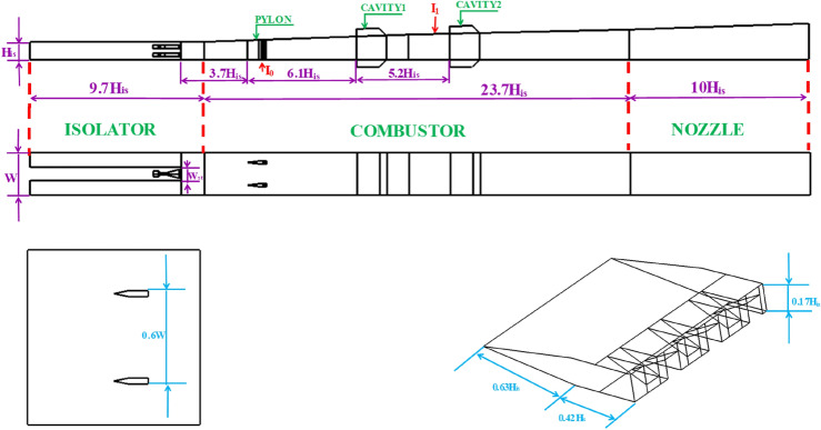
In this investigation, the RBCC configuration utilized the experimental model from the China Aerodynamics Research and Development Center, with Ma∞ = 5.5 being the designated operating point37. Geometric parameters of the RBCC model are illustrated in Fig. 138. The hypersonic inlet adopts a hybrid compression configuration with external compression angles of 8.3° and 9.8°, respectively. Boundary layer relief blocks are employed to mitigate combustion-induced airflow separation. Model parameters are normalized by the inlet throat height (His) and central strut width (W). The strut rocket adopts a single thrust chamber and dual nozzle configuration, with a nozzle expansion ratio of 6 (The expansion ratio is the area ratio between the end of the nozzle and the throat). Furthermore, two cavities are employed to create a recirculation zone with low velocity to stabilize the flame. The cavity’s aspect ratio (L/D) is set at 3.0. The first part of the combustion chamber has a volume ratio of 1.2, while the second part has a ratio of 1.8, allowing for flexibility to meet various performance requirements of RBCC engines. Three locations for kerosene fuel injection are incorporated in the engine: the isolator, the fuel strut (I0), and the upstream walls of the second pair of cavities (I1). Adopting a staggered structure, the struts facilitate accelerated fuel diffusion in the mainstream, enhancing mixing efficiency39. A total of 24 fuel nozzles, each with a diameter of 0.5 mm, are distributed on both sides for each fuel strut. Liquid kerosene is injected from the fuel strut in a direction perpendicular to the airflow.
Fig. 1.
Model diagram of the RBCC engine integrated model38.
Numerical methodology and validation
Numerical methodology
The three-dimensional RANS equations with chemical reactions are used to simulate the reacting viscous flow in the model RBCC engine by using Fluent40 as the following:
| 1 |
| 2 |
| 3 |
| 4 |
where , , , , , and are the component enthalpy, mass fraction, diffusion coefficient, fluid-phase density, and correlation coefficients, respectively. The shear stress tensor and energy term are addressed using the Menter Shear Stress Transport (SST) k–ω model. This model has undergone testing and demonstrated its applicability in the domain of supersonic flow.
When the droplet crosses the control volume, the changes in momentum, mass, and energy between gas phases and droplet during the period can be described as follows40:
| 5 |
| 6 |
| 7 |
where , , , , , , , , , , and are the velocity of the kerosene droplet, velocity of the flow fluid, drag coefficient, specific heat of the control volume, its temperature on the entry and exit, its temperature on the entry and exit, droplet’s density, droplet’s diameter, time step, relative Reynolds number, respectively. This numerical simulation method for scramjet engine has been validated in previous typical researches41,42.
The laminar finite rate model relies on solving the component transport equation and simulating the reaction through a customized chemical reaction mechanism. Therefore, this model is employed to simulate chemical reactions in this study. The kinetic model for chemical interactions adopts a reduced twelve-step reaction43. The validation of this kinetic model will be confirmed in the subsequent sections.
Arc plasma governing equation
The meaning of the momentum conservation equation is: within a specific time, the increment of momentum in the micro-element body is equal to the sum of various forces acting on the micro-element body44. Its expression is as follows:
| 8 |
Among them, F represents the various forces acting on the micro element.
Considering that the fluid microelements are subjected to viscous dissipation force (caused by relative motion between particles), frictional force, volume force of ions and electrons, thermal force (caused by electron temperature) and the centrifugal force of ions in the arc is much greater than that of electrons during MCGA discharge. The centrifugal force, the mass of the electron is much smaller than the mass of the ion, ignoring the viscous stress of the electron, the centrifugal force on the electron, the submass flow rate and the inertial component, the momentum equation can be obtained:
| 9 |
where B is the interpole magnetic induction intensity.
For MCGA, the ion temperature is much smaller than the electron temperature, and under the action of the external electric field, the electron gains kinetic energy and converts it into thermal energy; Ions, on the other hand, rely on elastic collisions between electrons and ions to obtain energy, while ionic heat terms can be ignored. In the supersonic vacuum arc, the arc current value is not high, and the radiation phenomenon of electrons and ions can be ignored while the influence of electronic viscous stress work on the electron temperature can be ignored. Combined with the above assumptions, the equation for conservation of electron and ion energy is as follows44:
| 10 |
| 11 |
where is the isobaric specific heat of electrons, is the specific heat of ion isobaric heat, and are electron and ion heat flux respectively; is the ion viscosity dissipation work; After electrons collide with ions, is the energy lost by electrons, and is the energy absorbed by ions; is the heat term of electrons.
There is a coupling relationship between the electric field and the magnetic field of MCGA, which has a non-negligible influence on the flow trend of sliding arc plasma and plasma characteristic parameters. The current density j and magnetic induction intensity B can be obtained from Maxwell’s equations and generalized Ohm’s law. Maxwell’s equations are as follows:
| 12 |
| 13 |
| 14 |
| 15 |
where is the charge body density; is vacuum permeability.
Unlike ordinary metals, in the plasma arc is affected by both temperature and pressure gradients, electromagnetic fields, etc., so the generalized Ohm’s law for fully ionized gases is as follows:
| 16 |
In summary, as shown in Fig. 228, arc plasma mainly achieves the combustion support effect on fuel through three methods. (1) By transferring energy and considering the influence of Joule heat, the temperature of the flow field is increased to strengthen the chain reaction. (2) Generate active free radicals. (3) Under the influence of magnetic and electric fields, the Lorentz and Coulomb forces generated by plasma alter the flow velocity and turbulence intensity of nearby fluids, thereby improving the mixing efficiency between air and fuel.
Fig. 2.
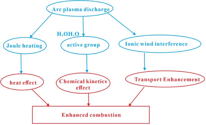
Principle of arc plasma combustion support28.
Boundary conditions and mesh
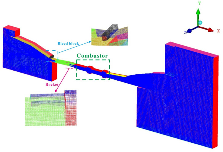
In this study, the full flow path configuration of RBCC engine structure is symmetric. In order to save calculation cost, the total grid cell is set at 2.05 million and half of the configuration is selected for calculation (Fig. 3).
Fig. 3.
Mesh of RBCC model.
Taking into account the impact of thermal protection and the reactivity of the secondary kerosene fuel, the oxygen-to-fuel ratio is established at 0.87. The initial total mass flow rate and entry temperature of the rocket are set at 0.2 kg/s and 1943 K, respectively. The mass fractions of high-temperature rocket gas are computed using the Chemical Equilibrium with Applications (CEA) code44: H2: 0.044, H2O: 0.246, CO2: 0.13, and CO: 0.58. The initial total equivalence ratio of the secondary fuel is 1.0. The pressure outlet condition is specified at the RBCC engine exit, with characteristic parameters set to ambient values, and the walls are designated as no-slip adiabatic wall boundaries. In this study, Ma∞ = 3.0 (ejector to ramjet mode) and 5.5 (ramjet to scramjet mode) are chosen as the research points. The flight conditions involve the boost phase (Ma∞ = 0–8) flight trajectory45.
Mesh sensitivity and validation
The validation data for the model is derived from free-jet test data conducted by the China Aerodynamics Research and Development Center at Ma∞ = 5 and an altitude of 21 km. The total equivalence ratio of kerosene fuel employed in the test is 0.9, with a focus on the I1 injection location38.
Independence verification is conducted using three mesh sizes: 426,000 (coarse), 1,260,000 (medium), and 2,050,000 (fine). The grid resolutions of 300 × 52 × 26, 440 × 75 × 38, and 513 × 88 × 45 are explored for the three density cases. To maintain a surface y + of the combustor less than 1, the distance of the first grid point off the wall is set to 1 × 10⁻⁴ mm.
In Fig. 4, the pressure variation along the centerline of the flow path is depicted, with Pi representing the reference pressure. It is noteworthy that, among the three grid configurations, the fine grids exhibit a more precise depiction of the shock train length in the isolator. In this study, the numerical simulation focuses on the internal flow field interaction within the inlet, isolator, combustor, and nozzle, utilizing a full flow path configuration. When investigating the dynamic characteristics of the RBCC flow field by altering fuel injection strategies, the parameters of the isolator and combustor undergo a continuously changing non-stationary process. Precisely capturing the starting and ending positions of the shock wave train in the isolator is crucial for accurately determining the extent of the high-pressure region in the combustor. Therefore, to ensure calculation accuracy, fine grids are employed in the numerical simulation research.
Fig. 4.
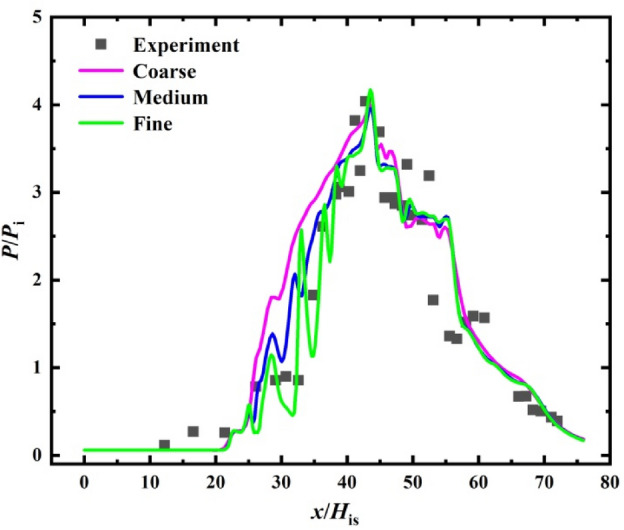
Validation results.
Results and discussion
Dynamic process of ejector/ramjet mode transition under Ma∞ = 3.0
Without plasma addition
This paper outlines a total of four designated working cases. Cases 1 and 2 are employed to analyze the dynamic characteristics of the flow field during the ejector/ramjet mode transition process of the RBCC engine, without and with plasma, respectively. Cases 3 and 4 are utilized to examine the flow field alterations during the transition process from ramjet to scramjet mode. The specific conditions for each case are detailed in Table 1.
Table 1.
Mode transition laws under different cases.
| Case | Mach number | Injection 0 ER | Injection 1 ER | Rocket (kg/s) | Plasma |
|---|---|---|---|---|---|
| 1 | 3.0 | 0.12 ~ 0.08 | 0.48 ~ 0.32 | 0.2 ~ 0.0 | None |
| 2 | 3.0 | 0.12 ~ 0.08 | 0.48 ~ 0.32 | 0.2 ~ 0.0 | Turn on |
| 3 | 5.5 | 0.2 ~ 0.08 | 0.8 ~ 0.32 | 0.2 ~ 0.0 | None |
| 4 | 5.5 | 0.2 ~ 0.08 | 0.8 ~ 0.32 | 0.2 ~ 0.0 | Turn on |
Due to the low flow velocity and total pressure at Ma∞ = 3.0, the anti-backpressure ability of the air inlet is greatly reduced, so it is necessary to explore the interaction between the air inlet, isolator, combustor and tail nozzle in the RBCC engine during the mode transition process of the ejector/ramjet mode. To investigate the primary diffusion combustion flame structure, a valuable parameter known as the mixing ratio Z is utilized, providing insight into premixed combustion flames46. The representation of Z is as follows:
| 17 |
In Eq. (17), Y represents the mass fraction, φ denotes the equivalence ratio, and its interpretation is . S signifies the mass ratio, expressed as , where W denotes the molecular mass. The mixture fraction under stoichiometric conditions, is defined as 0.0626. The remaining boundary conditions are outlined in Table 2.
Table 2.
Inflow condition of RBCC engine under Ma∞ = 3.0/
| Parameters | Value |
|---|---|
| Mach number | 3.0 |
| Static pressure (MPa) | 0.0286 |
| Static temperature (K) | 226.4 |
| O2 mass fraction | 0.2031 |
| N2 mass fraction | 0.7969 |
| Initial total equivalent ratio of kerosene | 1 |
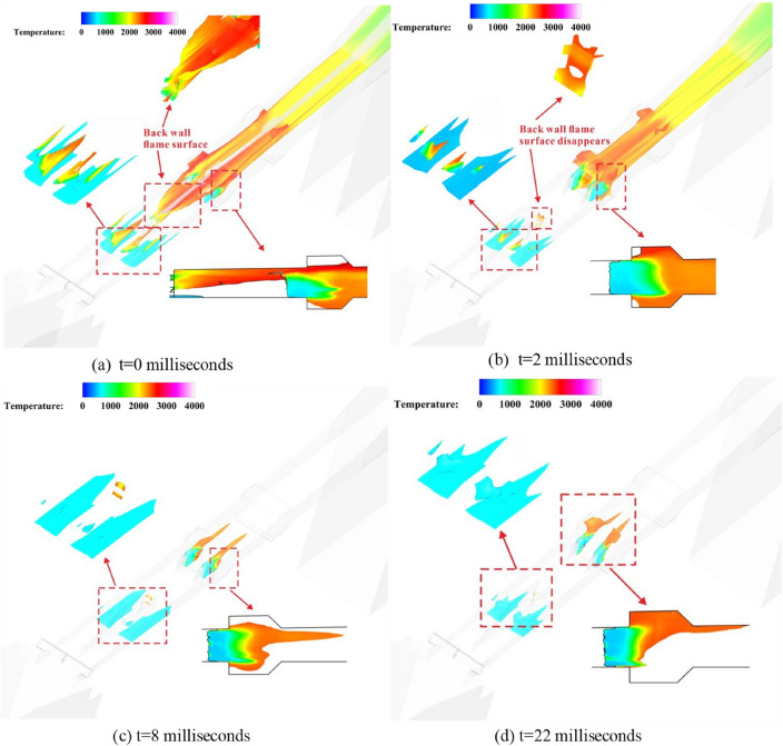
Figure 5 illustrates the flame structure under Case 1 conditions, where the flame surface is defined by = 0.0626, flooded by temperature. In Fig. 6, the pressure variation during the mode transition process is presented. It is observed that initially, the temperature on the flame surface is high and can propagate nearly throughout the entire combustor when the fuel equivalence ratio is large. By t = 2 ms, as the kerosene fuel equivalence ratio decreases and the rocket hot jet is turned off, the high-temperature zone on the flame surface in the isolator diminishes. Additionally, the mixing layer formed by the rocket jet and the air at the back wall of the main strut gradually dissipates. The low temperature zone of the flame surface of the trailing edge of the fuel strut increases, but the high temperature flame surface can still exist stably in the cavity.
Fig. 5.
Two-phase flame surface structure: temperature equivalent surface on the surface of mixing fraction Zst = 0.0626 in Case 1. (a) t = 0 ms; (b) t = 2 ms; (c) t = 8 ms; (d) t = 22 ms.
Fig. 6.
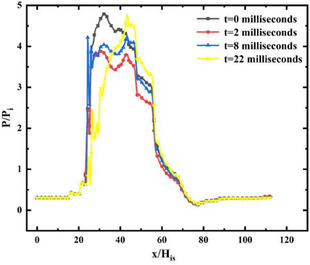
The pressure distribution curve in Case 1. (Data extracted from the line: X = 0–112His, Y = 0.86His, Z = 0.025His).
With the passage of time, by t = 22 ms, the flow field in RBCC is stable, the mode transition process is completed, and there is no high-temperature flame surface in the isolator. After losing the role of the high-temperature jet of the rocket, kerosene is injected by the isolator with a lower equivalent ratio, cannot be effectively blended and burned with the incoming air in time, resulting in flame extinguishing. In contrast, the flame stabilization zone composed of the tail of the fuel strut and the first pair of cavities in the combustor can fully ignite the fuel. Although the high-temperature flame surface is reduced, it is always stable. On the pressure distribution curve, it can be clearly seen that the high pressure region first decreases and then increases in the process of mode transition, and the range of the high pressure region gradually shifts backward with time. Finally, the pressure at the fuel strut reaches a maximum of 4.6 Pi.
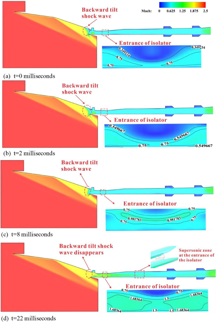
Figure 7 illustrates the Mach number contour at the z = 1His section, and Fig. 8 presents the average Mach number distribution along the x-axis under Case 1 conditions. In Fig. 7a during the ejector mode, the intensity of the shock train in the isolator is insufficient to withstand the back pressure increase in the combustor, resulting in its complete expulsion from the isolator. Additionally, flow separation on the wall surface is mitigated with the bleed block. At this juncture, the inflow enters the inlet at subsonic speeds, leading to the formation of a large-scale subsonic region.
Fig. 7.
Mach number distribution of section z = 1His. (a) t = 0 ms; (b) t = 2 ms; (c) t = 8 ms; (d) t = 22 ms.
Fig. 8.
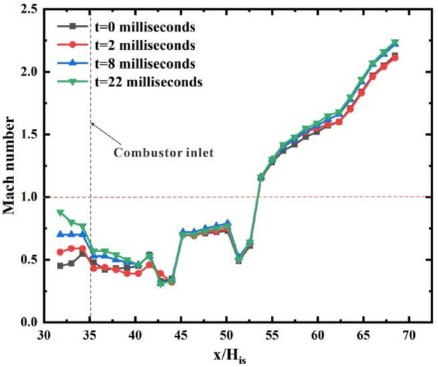
The average Mach number distribution curve of the x-axis in Case 1.
As seen in Fig. 7c, with the time to 8 ms, the weakening of the combustion intensity in the combustor leads to a decrease in the pressure. The flow separation zone near the bleed block nearly vanishes, and the backward-tilted shock wave is reflected by the wall and approaches the inlet lip. Furthermore, the deceleration and boosting effect are diminished, resulting in an enhancement of the Mach number at the combustor inlet. Although a small area close to the speed of sound appears in the central area at the entrance of the isolator and the average Mach number in the isolator has slightly increased, it still runs through the entire isolator at subsonic speed. The inlet is still in an unstart state. When the mode transition is completed, as seen in Fig. 7d, at t = 22 ms, the flame in the isolator is extinguished due to the loss of the rocket’s high-temperature jet, and the heat release position of the fuel moves back, causing the high-pressure area in the combustor to move downstream. It can be seen that the flow separation area near the bleed block has completely disappeared, and the backward shock wave formed due to the influence of flow separation has also disappeared. The pre-combustion shock train is stable in the isolator, except for the small boundary near the wall. The air inlet is in a start-up state. The inlet of the combustor exhibits a supersonic/subsonic mixed flow state dominated by subsonic flow. It can be seen that although the mass flow rate of the fuel has been significantly reduced, there is only a slight change in the average Mach number distribution in the combustor of the RBCC engine during the mode transition process, which further demonstrates the importance of the starting state of the inlet for the performance of the RBCC engine at low Mach numbers.
Enhance of Arc plasma on combustion
To improve the performance of RBCC engine, arc plasma is added to the RBCC mode transition process in Case 2. In order to prevent a large degree of overflow caused by the poor anti-backpressure capability of the air inlet at low Mach number, as shown in Fig. 9, it is only installed in the rear of the combustor, that is, in the second pair of cavities, and the boundary condition adopts 10000 V DC power supply.
Fig. 9.
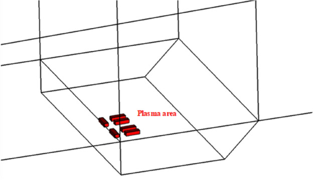
Arc plasma action area in Case 2.
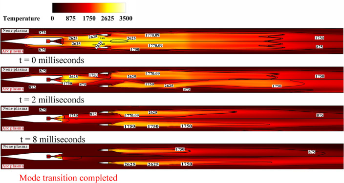
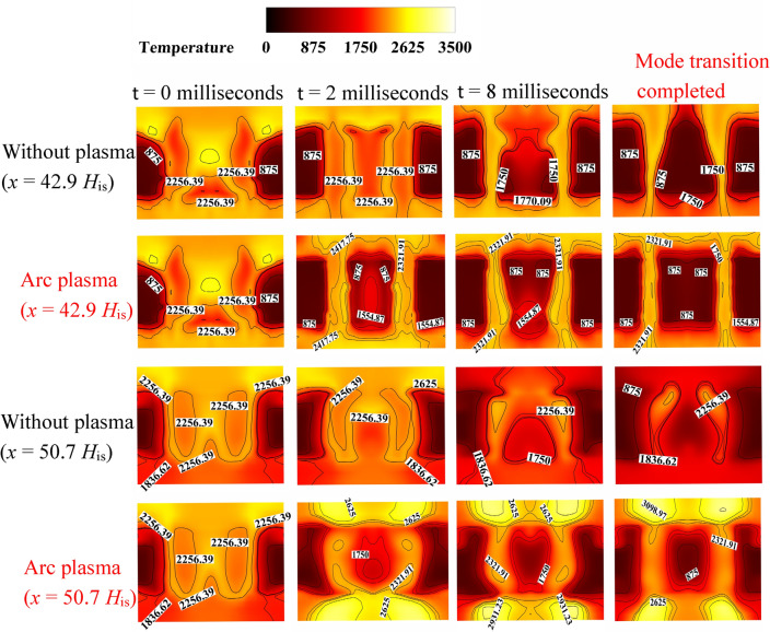
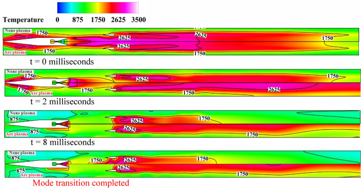
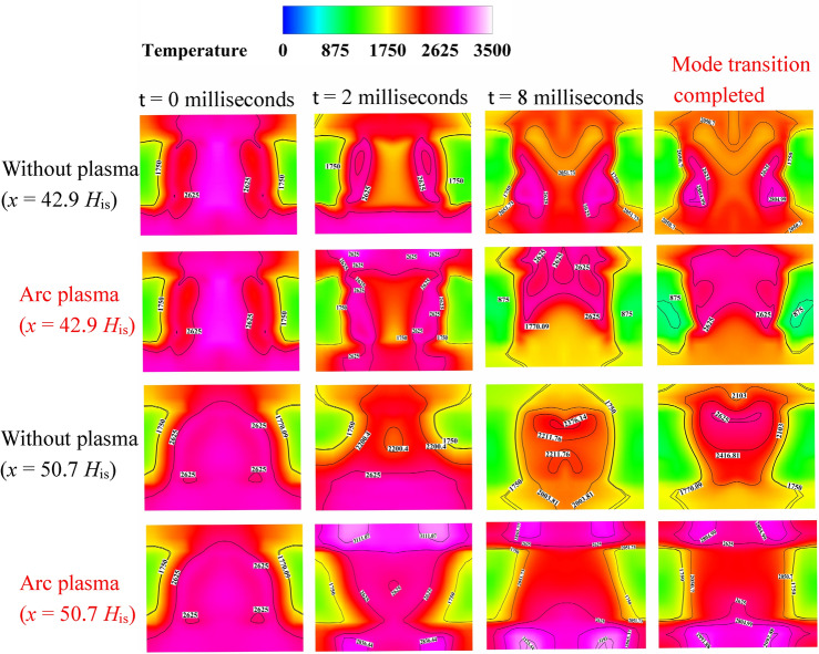
Figure 10 shows the temperature distribution contour on the plane of y = 1His during the process of ejector/ramjet mode (the upper half is Case 1 without plasma combustion support, the lower half is Case 2 with arc plasma added in the second pair of cavities). Figure 11 shows the temperature contour of the x-axis sections at the center of two pairs of cavities under two cases. It can be seen that at t = 2 ms, a high temperature zone of 3000 K has been established in the second pair of cavities in the combustor due to the temperature rise in the plasma interaction area. Although the range of the high pressure zone does not increase significantly, the high pressure value reaches 4.5Pi, which is about 0.5Pi higher than the Case 1(without plasma). At t = 16 ms, the stability of the flow field means the completion of the mode transition process, and the entire transition time is shortened by 6 ms, indicating that under the action of arc plasma combustion support, the engine can adapt more quickly to the decrease in combustion intensity caused by fuel reduction in the flow field, and.
Fig. 10.
Temperature distribution contour on the plane of y = 1His in Case 1 (upper half) and Case 2 (lower half).
Fig. 11.
Temperature distribution contour of two pairs of cavity central x-axis sections.
reorganize stable combustion. From the analysis of the pressure curve (Fig. 12), it can be seen that under the action of plasma, the pressure fluctuation of the flow field is small during the mode transition process, and the stability of the flow field is improved. After the flow field is stabilized, although the maximum value of the flow path pressure remains at about 4.6Pi, the range of the high-pressure area is extended to x = 32His-50His. It can be seen that the range of the high-pressure area in the first section of the combustor has been significantly improved, and the heat release range of the fuel in the front is expanded. Although the kerosene fuel injected into the isolator cannot be effectively ignited upstream after the mode transition is completed, the propagation of downstream flames in the spanwise direction is enhanced under the action of the plasma high-temperature region in the second pair of cavities, and the diffusion ability of high-temperature flames is also improved.
Fig. 12.
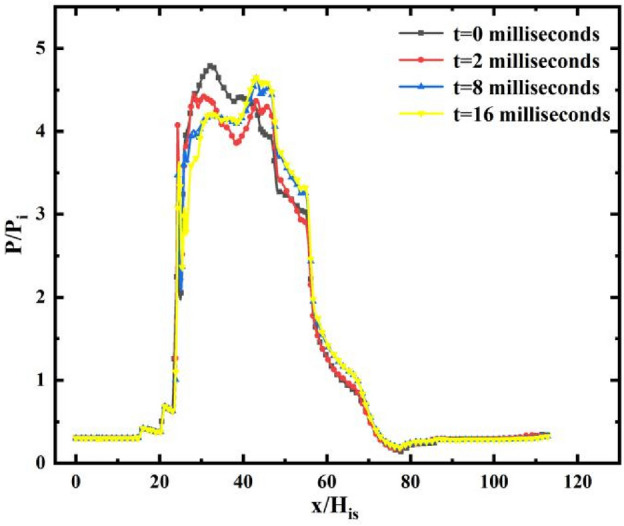
The pressure distribution curve in Case 2. Data extracted from the line: X = 0–112His, Y = 0.86His, Z = 0.025His.
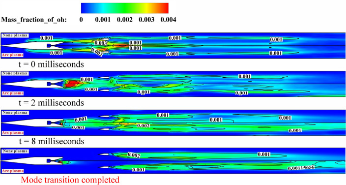
Figure 13 is the contour of the mass fraction distribution of intermediate product OH on the plane y = 1His in Case 1 (upper part) and Case 2 (lower part). It can be seen from that at t = 2 ms, the increase in OH distribution after the addition of arc plasma is mainly reflected in the area between the first pair and the second pair of cavities. Over time, the OH distribution gradually diffuses downstream, and finally forms a distribution trend that starts from the fuel strut and gradually fills the entire combustor.
Fig. 13.
OH distribution contour on the plane of y = 1His in Case 1 (upper half) and Case 2 (lower half).
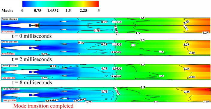
Figure 14 is the contour of the Mach number distribution on the plane y = 1His in Case 1 (upper part) and Case 2 (lower part). Figure 15 shows the Mach number distribution contour of the x-axis sections at the isolator inlet during the mode transition process under two working cases. It can be seen that when the plasma starts to act, because the combustor is long and the action position is far away, the back pressure generated by combustion has not propagated upstream, and the Mach number distribution of case 1 and case 2 is very similar. But when the time reaches 8 ms, the high back pressure caused by the plasma combustion assistance propagates upstream, and the low subsonic region in the central flow of the combustor continues to expand. However, the position of the thermal chocking remains unchanged and stabilizes at the leading edge of the second pair of cavities. After the flow field is stabilized, the region at the entrance of the isolator still maintains subsonic. The difference is that in Case 1, the supersonic velocity area appears near the two sides of the wall. The reason for this difference is that in the absence of plasma assisted combustion, the local pressure rise caused by liquid kerosene injection in the isolator does not affect the upstream region through the low-speed region of the boundary layer, thus increasing the Mach number at the entrance of the isolator. It can be seen from the previous analysis that when the fuel equivalent ratio is reduced, the combustion intensity in the combustor is greatly reduced, resulting in the disappearance of flow separation near the wall and the resumption of the start-up state of the air inlet.
Fig. 14.
Mach number distribution contour on the plane of y = 1His in Case 1 (upper half) and Case 2 (lower half).
Fig. 15.
The Mach number contour of the x-axis sections at the entrance of the isolator during the RBCC mode transition in Case 1 and Case 2.
Obviously, although the arc plasma arrangement has been placed at the rear of the combustor, the overflow phenomenon will still occur due to the poor anti-backpressure resistance of the air inlet, resulting in a reduction in the mass flow rate of captured air in the inlet. Therefore, although the arc plasma has obvious effect on fuel combustion, which helps to extend the range of high-temperature flame, promote the chain reaction, and improve the combustion efficiency of fuel. It is necessary to combine the configuration of the engine and the actual flight situation, and give different arrangement schemes according to different flow conditions to meet the matching of RBCC performance.
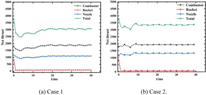
Figure 16 depicts the thrust curves during the RBCC mode transition in Case 1 (kerosene equivalent ratio reduced from 0.6 to 0.4, rocket total mass flow rate from 0.2 kg/s to 0 kg/s, without plasma) and Case 2 (kerosene equivalent ratio reduced from 0.6 to 0.4, rocket total mass flow rate from 0.2 kg/s to 0 kg/s, arc plasma added to the second pair of cavities). Comparing with Case 1 (without plasma action), in Case 2, although the net thrust generated by the rocket wall quickly diminishes to near zero after the main rocket is shut down under the influence of plasma, the thrust produced by the tail nozzle increases from 1100 to 1300 N. The total thrust trough (lowest value) is 3000 N, indicating an increase of 500 N. Although there is still an overflow in the air inlet and the mass flow rate of captured air quality is reduced, the net thrust generated by the combustor after the flow field is stabilized remains at about 1800N and has not decreased. During the whole mode transition process, the thrust fluctuation of the combustor is small in Case 2, and the lowest value reaches 1750N. On the contrary, although the wall flow separation area is greatly reduced in Case 1, the minimum thrust value in the mode transition process is reduced to 1500N in about 5 ms, and the thrust fluctuation amplitude is relatively large. It can be seen that the performance of RBCC engine under low Mach number needs to be considered by comprehensive flow conditions and fuel heat release. The introduction of arc plasma promotes the heat release of fuel, and improves the reaction ability of fuel. Although it weakens the ability of part of the air inlet to capture air, it generally improves the thrust performance of the engine. Therefore, the engine passes the thrust instability stage in the mode transition more smoothly in the process of reducing the fuel equivalent ratio.
Fig. 16.
Thrust variation curves during mode transition.
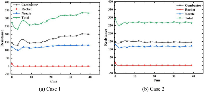
Figure 17 illustrates the resistance curves during the RBCC mode transition in Case 1 (kerosene equivalent ratio reduced from 0.6 to 0.4, rocket total mass flow rate from 0.2 kg/s to 0 kg/s, without plasma) and Case 2 (kerosene equivalent ratio reduced from 0.6 to 0.4, rocket total mass flow rate from 0.2 kg/s to 0 kg/s, arc plasma added to the second pair of cavities). Figure 18 shows the pressure distribution contour on the first section of the combustor in Case 1 and Case 2(z = -0.6His). Although the arc plasma is only arranged in the second pair of cavities, located downstream of the combustor, due to the low flow velocity and long combustor, the incoming air and kerosene fuel have sufficient time to mix, even if there is no effect of plasma, the main heat release area of the combustor is still stabilized near the first pair of cavities. The high pressure area is maintained at about 400000 Pa. After applying plasma, the position of the main heat release zone did not change, but the pressure in the cavity significantly increased, resulting in a small range of pressure zone of about 440,000. The reaction zone in the mainstream was expanded to a larger area by the plasma, which means that the combustion intensity in the combustor is enhanced, and a larger reaction zone will lead to higher back pressure. From the resistance change curve during the mode transition process, it can be seen that without the assistance of plasma, the resistance in the combustor shows an upward trend after fuel throttling, ultimately reaching 200N. The resistance in the tail nozzle has hardly changed, so the fluctuation of total resistance is mainly generated by the combustor In Case 2, after adding plasma, the resistance generated in the combustor remained almost unchanged, stable at around 150N, a decrease of 25%, and the total resistance fluctuation is stable. Compared with Case 1, it decreased from 325 to 275N, a decrease of 15.4%.
Fig. 17.
Resistance variation curves during mode transition.
Fig. 18.
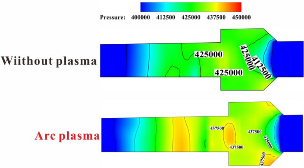
Contour of pressure distribution on the plane of z = − 0.6His of the first combustor in Case 1 (upper part) and Case 2 (lower part).
Dynamic process of ramjet/scramjet mode transition under Ma∞ = 5.5
At a high Mach number, it is mainly aimed at the problems of low fuel mixing efficiency and insufficient heat release. In order to improve the heat release capacity of the fuel and increase the thrust of the RBCC engine during the mode transition process, simultaneously set arc plasma domains of the same size at the first and second pair of cavities in the combustor, and a 10000 V DC power supply is used as the boundary condition. The boundary conditions of the incoming flow are listed in Table 3.
Table 3.
Inflow condition of RBCC engine under Ma∞ = 5.5.
| Parameters | Value |
|---|---|
| Mach number | 5.5 |
| Static pressure (MPa) | 0.0069 |
| Static temperature (K) | 216.65 |
| O2 mass fraction | 0.2031 |
| N2 mass fraction | 0.7969 |
| Initial total equivalent ratio of kerosene | 1 |
Figure 19 shows the temperature distribution contour on the plane of y = 1His during the process of ramjet/scramjet mode (the upper half is Case 3 without plasma combustion support, the lower half is Case 4 with arc plasma added in the cavities). Figure 20 shows the temperature contour of the x-axis sections at the center of two pairs of cavities under two cases. It can be seen that with the shutdown of the rocket, the fuel equivalent ratio decreases, the temperature distribution of the flow field at 2 ms is highly similar, and the flame in the isolator has not been extinguished, the difference is that a high temperature area of about 3100 K has been produced under the action of arc plasma in the cavity of the combustor in Case 4. The distribution of pressure curves in the combustor is consistent, it indicates that the combustion support effect of plasma on the fuel has not spread upstream in a short time, which has no significant effect on the internal flow field.
Fig. 19.
Temperature distribution contour on the plane of y = 1His in Case 3 (upper half) and Case 4 (lower half).
Fig. 20.
Temperature distribution contour of two pairs of cavity central x-axis sections.
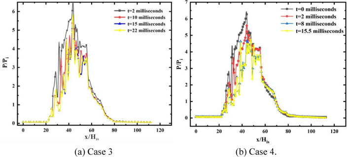
When the time comes to the 8 ms, the flame range has been reduced to the front edge of the fuel strut in Case 3 where the plasma is not added. Although the high-temperature flame area still decreases in Case 4, some high-temperature flame areas are still retained upstream of the first part of combustor. From the distribution range of the high-pressure zone (Fig. 21), under the action of plasma, the high-pressure zone has expanded to x = 38His-58His compared to Case 3, indicating that plasma has increased the pressure of the combustor and expanded the coverage range of the high-temperature flame zone. Finally, with the consumption of residual high-temperature rich combustion gas in the rocket, stable combustion is reorganized in the combustor. After the flow field stabilizes, a high-temperature flame is re-established upstream of the fuel strut in Case 3, and the combustion range expands upstream. On the other hand, the internal flow field characteristics in Case 4 show that during the mode transition process, the flow field fluctuation is relatively small. The mode transition process is completed at t = 15.5 ms in Case 4, and the distribution range of the high pressure zone is wider. This shows that the combustion support effect of arc plasma is of great significance to improve the working stability of the engine in the ramjet/scramjet mode transition process, which not only expands the range of high pressure zone, but also improves the fuel combustion efficiency and shortens the time required for the mode transition process.
Fig. 21.
The pressure distribution curves. Data extracted from the line: X = 0-112His, Y = 0.86His, Z = 0.025His.
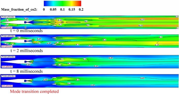
Figure 22 is the contour of the mass fraction distribution of product CO2 on the plane y = 1His in Case 3 (upper part) and Case 4 (lower part). This shows, at 2 ms, in Case 1 without arc plasma addition, the mass fraction of CO2 in the isolator and the reflux zone behind the rocket strut rapidly decayed. The CO2 between the rocket outlet and the fuel strut almost disappeared. Although the mass fraction of CO2 in the central flow decreased significantly in the downstream of the combustor, the distribution width did not decrease. However, in Case 4 with arc plasma addition, a small amount of CO2 is still retained in the isolator and the recirculation area behind the rocket strut. The overall reduction of the products in the central flow of the combustor is small. Therefore, after adding plasma for combustion in the same period of time, the RBCC combustion intensity decreases less, and the engine performance is more stable.
Fig. 22.
CO2 distribution contour on the plane of y = 1His in Case 3 (upper half) and Case 4 (lower half).
Although in Case 4, after the mode transition process is completed, the flame is extinguished due to a decrease in fuel combustion intensity in the isolator and the complete combustion product CO2 is almost non-existent in front of the strut, its propagation and diffusion ability are improved in the combustor, with a wider distribution range. The chain reaction of kerosene combustion is promoted, which extends the combustion reaction area and forms a higher intensity combustion reaction. Due to the low speed reflux zone formed in the cavities, fuel can be sucked into the cavity, resulting in a large distribution of fuel. Therefore, adding arc plasma to the cavities can more effectively utilize the flame stabilization advantage of the combination of fuel strut and cavities, better utilize the combustion organization characteristics of the shear layer.
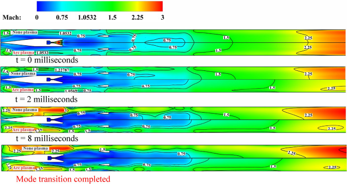
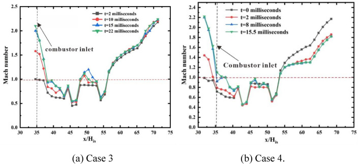
Figure 23 is the contour of the Mach number distribution on the plane y = 1His in Case 3 (upper part) and Case 4 (lower part). Figure 24 shows the Mach number distribution contour of the x-axis sections at the isolator inlet during the mode transition process under two working cases. Figure 25 respectively display the average Mach number distribution of the x-axis sections of the flow path in Case 3 and Case 4. Unlike in the previous chapter at low Mach numbers, the inlet is consistently in the starting state during the transition from ramjet mode to scramjet mode at Ma∞ = 5.5 due to its robust anti-backpressure capability. Therefore, the addition of plasma does not influence the inlet’s ability to capture air. During the mode transition process, both Case 3 and Case 4 undergo a transition from subsonic to supersonic at the entrance of the combustor. However, in Case 3, with no plasma assisted combustion, after the rocket is shut down and the kerosene equivalent ratio is reduced, the combustion intensity of the fuel decreases significantly, resulting in a larger increase in Mach number. After the flow field is stabilized, the flow area at the entrance of the combustor is at supersonic speed, with an average Mach number of 1.8, and even a supersonic region with Mach number of 3 appears on both sides of the wall.
Fig. 23.
Mach number distribution contour on the plane of y = 1His in Case 3 (upper half) and Case 4 (lower half).
Fig. 24.
The Mach number contour of the x-axis sections at the entrance of the isolator during the RBCC mode transition in Case 3 and Case 4.
Fig. 25.
The average Mach number distribution curves of the x-axis.
In Case 4, the arc plasma enhances the propagation and diffusion ability of high-temperature flames in the combustor, promotes the chain reaction of kerosene, and improves combustion intensity. After the flow field stabilizes, the combustor entrance presents a mixed region dominated by supersonic and subsonic velocities, with an average Mach number of only 1.1 at the combustor entrance. This further indicates that the plasma greatly improves the heat release of the fuel. The subsonic region near the fuel inlet in the isolator indicates that RBCC can still maintain small-scale combustion in the upstream part of the engine after shutting down the rocket and reducing the fuel equivalence ratio, which undoubtedly expands the heat release distribution area of the fuel.
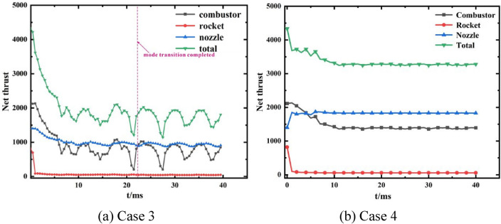
Figure 26 illustrates the thrust profiles during the RBCC mode transition for Case 3 (kerosene equivalent ratio reduced from 1 to 0.4, rocket total mass flow rate from 0.2 kg/s to 0 kg/s, without plasma) and Case 4 (kerosene equivalent ratio reduced from 1 to 0.4, rocket total mass flow rate from 0.2 kg/s to 0 kg/s, with arc plasma added to the cavities).
Fig. 26.
Thrust variation curves during mode transition.
Compared with Case 3 without plasma action, it can be seen that under the action of plasma in Case 4, although the net thrust generated by the rocket wall rapidly decays to zero after the main rocket is closed, the thrust generated by the tail nozzle increases from 1400 to 1800N, and the total thrust trough (minimum value) is 3300N, increasing by 1500N. During the entire mode transition process, the thrust in the combustor decreased from 2100N in the ramjet mode to 1450N in the scramjet mode. The thrust fluctuated smoothly during the mode transition process, and the transition time was shortened to 15.5 ms. On the other hand, Case3 without plasma, the thrust of the combustor decreases to around 500N during the scramjet stage after the mode transition is completed, with a significant fluctuation and a long transition time, which is extremely detrimental to engine performance.
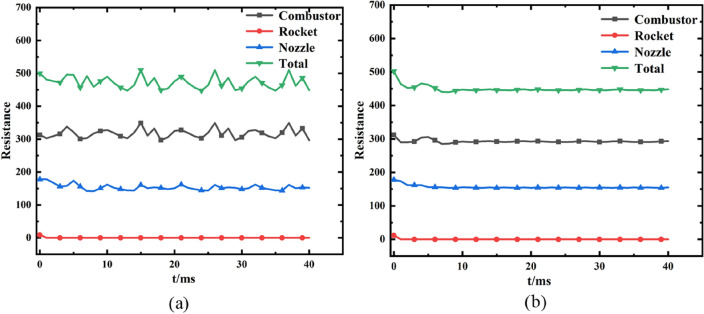
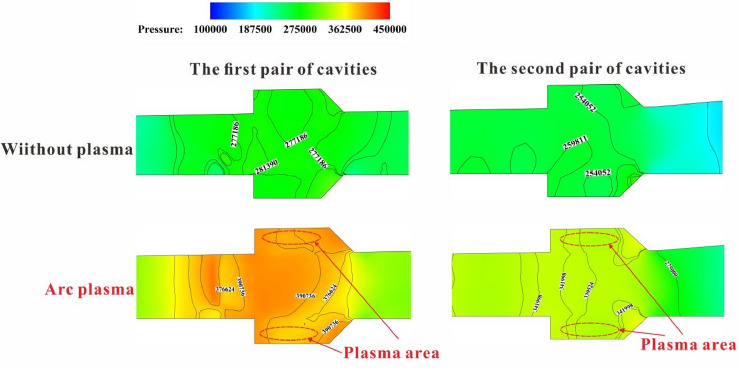
Figure 27 shows the resistance curves during the RBCC mode transition in Case 3 and Case 4. Figure 28 shows the pressure distribution contour on the section of the combustor in Case 3 and Case 4(z = -0.6His). Without the assistance of plasma, the resistance in the combustor shows an unstable state after fuel throttling, ultimately reaching 325N. The resistance in the tail nozzle remains almost unchanged, so the fluctuation of total resistance is mainly generated by the combustor. In Case 4, after adding plasma, the resistance generated in the combustor during the mode transition process remained almost unchanged, stable at around 280N, a decrease of 14%, and the total resistance fluctuated steadily. Compared with Case 3, it decreased from 500 to 450N, a decrease of 10%. From the pressure distribution contour in the cavities, it can be seen that after applying plasma, the pressure in the main heat release zone (the first pair of cavities) has significantly increased, with a large range of high pressure areas around 400000 Pa. The pressure growth in the downstream of the combustor (the second pair of cavities) is relatively small, and the reaction zone in the mainstream is expanded to a larger area by the plasma, which means that the combustion intensity in the combustor is enhanced. Larger reaction zone will result in higher back pressure in the burner, resulting in an increase in the net thrust generated by the combustor.
Fig. 27.
Resistance variation curves during mode transition. (a) Case 3; (b) Case 4.
Fig. 28.
Pressure distribution on the z = − 0.6His cross-section in two pairs of concave cavities.
Conclusion
This research proposes to apply arc plasma to assist combustion in the mode transition process in RBCC engine. The detailed flow field and flame structure are obtained by numerical simulation. The following conclusions can be drawn:
The working state of the air inlet at low Mach numbers has a close impact on the combustion situation in the combustor. When the Mach number is 3.0, the inlet achieves a transition from non start to start during the ejector/ramjet mode transition process by shutting down the rocket and reducing the fuel equivalence ratio.
At low Mach numbers, the performance of RBCC engines needs to be considered comprehensively based on the inflow conditions and the incorporation of arc plasma enhances the heat release and work output of the fuel, positively impacting the overall performance of the engine. Despite diminishing the air-capturing capability of certain air inlets, it results in a net improvement in thrust performance and a reduction in resistance from the combustor wall. This enhancement enables the engine to navigate through the thrust instability phase of the mode transition process more seamlessly.
High Mach numbers lead to swift inflow velocities, impeding the timely mixing of fuel with air for combustion. This, in turn, hinders efficient heat release and work performance. However, after adding arc plasma for combustion support, after the mode transition process is completed, the high-temperature flame propagation and diffusion ability is improved in the combustor, with a wider overall distribution range. The chain reaction of kerosene combustion is promoted, which extends the combustion reaction area and forms a higher intensity combustion reaction. Significantly improved the thrust performance of the engine, alleviated the phenomenon of sudden thrust drop during mode transition, greatly shortened the time required for mode transition, and reduced engine resistance.
Acknowledgements
This work was financially supported by National Natural Science Foundation of China (Grant No. 52376126), the Natural Science Basic Research Program of Shaanxi Province (Program No. 2022JM-231), Key independent Research Program of State Key Laboratory for Strength and Vibration of Mechanical Structures (Grant No. SV2023ZD05).
Author contributions
Wei-Rui Zhang and Yuan-Shu Liu wrote the main manuscript text and Xiang-Rui Zou, Chaoqi Xu, Rui Xue contributed to the methods, ideas and as supervision. All authors reviewed the manuscript.
Data availability
The datasets used and/or analysed during the current study available from the corresponding author on reasonable request.
Declarations
Competing interests
The authors declare no competing interests.
Footnotes
Publisher’s note
Springer Nature remains neutral with regard to jurisdictional claims in published maps and institutional affiliations.
Contributor Information
Chaoqi Xu, Email: huchunbo63@163.com.
Rui Xue, Email: ruixue@xjtu.edu.cn.
References
- 1.U. Hueter, C.R. McClinton, NASA’s advanced space transportation hypersonic program. AIAA 2002–5175.
- 2.J. Olds, Options for flight testing rocket-based combined cycle (RBCC) engines. AIAA 96–2688.
- 3.N.W. Mercurio, S. Pal, R. Woodward, Experimental studies of the unsteady ejector mode of a pulse detonation rocket-based combined cycle engine. AIAA 2010–6882, 2010.
- 4.Gong, C. L. & Han, L. Optimization of ascent. Trajectory for RBCC-powered RLV. J. Solid Rocket Technol.35(3), 290–295 (2012). [Google Scholar]
- 5.Ye, K., Ye, Z. Y., Li, C. N. & Wu, J. Effects of the aerothermoelastic deformation on the performance of the three-dimensional hypersonic inlet. Aerosp. Sci. Technol.84, 747–762 (2019). [Google Scholar]
- 6.Yu, K. K., Xu, J. L., Li, R., Liu, S. & Zhang, X. F. Experimental exploration of inlet start process in continuously variable Mach number wind tunnel. Aerosp. Sci. Technol.79, 75–84 (2018). [Google Scholar]
- 7.Yue, L. J., Jia, Y. N., Xu, X., Zhang, X. Y. & Zhang, P. Effect of cowl shock on restart characteristics of simple ramp type hypersonic inlets with thin boundary layers. Aerosp. Sci. Technol.74, 72–80 (2018). [Google Scholar]
- 8.Xie, W. Z., Ge, Y., Chen, H., Wen, Y. F. & Guo, S. M. Rapid supersonic performance prediction for 2D ramjet inlets. Aerosp. Sci. Technol.53, 220–231 (2016). [Google Scholar]
- 9.Trefny, C.J. An air-breathing launch vehicle concept for single-stage-to-orbit, AIAA Paper 99–2730.
- 10.Thomas, S.R., Palac, D.T., Trefny, C.J., Roche, J.M. Performance evaluation of the NASA, GTX RBCC flowpath, ISABE Paper 2001–1070.
- 11.Mahoney, J. J. Inlets for Supersonic Missiles (AIAA Education Series, 1991). [Google Scholar]
- 12.Zhang, C. L., Chang, J. T., Feng, S., Bao, W. & Yu, D. R. Investigation of performance and mode transition in a variable divergence ratio dual-mode combustor. Aerosp. Sci. Technol.80, 496–507 (2018). [Google Scholar]
- 13.Hao, X. Y., Chang, J. T., Bao, W. & Zhang, Z. X. A model of mode transition logic in dual-mode scramjet engines. Aerosp. Sci. Technol.49, 173–184 (2016). [Google Scholar]
- 14.Cao, R. F., Chang, J. T., Tang, J. F., Wang, Z. Q. & Yu, D. R. Study on combustion mode transition of hydrogen fueled dual-mode scramjet engine based on thermodynamic cycle analysis. Int. J. Hydrog. Energy39(36), 21251–21258 (2014). [Google Scholar]
- 15.Yang, Q. C. et al. A mechanism of combustion mode transition for hydrogen fueled scramjet. Int. J. Hydrog. Energy39(18), 9791–9797 (2014). [Google Scholar]
- 16.P. K. McConnaughey, M.G. Femminineo, S.J. Koelfgen, R.A. Lepsch, R.M. Ryan, S.A. Taylor, Launch propulsion systems roadmap (Technology Area 01), NASA, (2012).
- 17.Zhang, S., Li, J. & Qin, F. Numerical investigation of combustion field of hypervelocity scramjet engine. Acta Astronaut.129, 357–366 (2016). [Google Scholar]
- 18.Wang, Y., Li, J. & Qin, F. Study of thermal throat of RBCC combustor based on one-dimensional analysis. Acta Astronaut.117, 130–141 (2015). [Google Scholar]
- 19.Trefny, C. An air-breathing launch vehicle concept for single-stage-to-orbit. In 35th Joint Propulsion Conference and Exhibit, 2730 (1999).
- 20.Yungster, S., Trefny, C. Analysis of a new rocket-based combined-cycle engine concept at low speed. In 35th Joint Propulsion Conference and Exhibit, 2393 (1999).
- 21.J. Chun, T. S., et al. Experimental study on combustion mode transition in a scramjet with parallel injection. In 14th AIAA/AHI Space Planes and Hypersonic Systems and Technologies Conference, 8063 (2006).
- 22.Sullins, G. A. Demonstration of mode transition in a scramjet combustor. J. Propul. Power9(4), 515–520 (1993). [Google Scholar]
- 23.Byrne, S., Doolan, M. & Olsen, S. R. Analysis of transient thermal choking processes in a model scramjet engine. J. Propul. Power16(5), 808–814 (2000). [Google Scholar]
- 24.Kanda, T., Chinzei, N. & Kudo, K. Dual-mode operations in a scramjet combustor. J. Propul. Power20(4), 760–763 (2004). [Google Scholar]
- 25.Masumoto, R., Tomioka, S. & Kudo, K. Experimental study on combustion modes in a supersonic combustor. J. Propul. Power27(2), 346–355 (2011). [Google Scholar]
- 26.Huang, S. et al. Experimental investigation of multichannel plasma igniter in a supersonic model combustor. Exp. Therm. Fluid Sci.99, 315–323 (2018). [Google Scholar]
- 27.Feng, R. et al. Ignition and combustion enhancement in a cavity-based supersonic combustor by a multi-channel gliding arc plasma. Exp. Thermal Fluid Sci.120, 110248 (2021). [Google Scholar]
- 28.Ju, Y. & Sun, W. Plasma assisted combustion: Dynamics and chemistry. Progr. Energy Combust. Sci.48, 21–83 (2015). [Google Scholar]
- 29.A. Klimov, V. Byturin, I. Moralev, et al. Non⁃premixed plasma ⁃ assisted combustion in high speed airflow. In 44th AIAA Aerospace Sciences Meeting & Exhibit, 1⁃10 (AIAA, 2006).
- 30.Chintala, N. et al. Nonthermal ignition of premixed hydrocarbon ⁃ air and co ⁃ airflows by non ⁃equilibrium RF plasma. In 42th AIAA Aerospace Sciences Meeting & Exhibit, 1⁃18 (AIAA, 2004).
- 31.Chintala, N. et al. Non-thermal ignition of premixed hydrocarbon-air flows by non-equilibrium radio frequency plasma. J. Propul. Power21(4), 583–590 (2005). [Google Scholar]
- 32.Feng, R. et al. Suppression of combustion mode transitions in a hydrogen-fueled scramjet combustor by a multi-channel gliding arc plasma. Combust. Flame237, 111843 (2022). [Google Scholar]
- 33.Tian, Y. F. et al. Combustion enhancement in a model scramjet by a simple pin-to-pin AC arc plasma. Proc. Combust. Inst.1–4, 105259 (2024). [Google Scholar]
- 34.Li, Q. et al. Investigation of ignition and flame propagation in an axisymmetric supersonic combustor with laser-induced plasma. Phys. Fluids35(12), 125133 (2023). [Google Scholar]
- 35.Tian, Y. et al. Enhancement of blowout limit in a Mach 2.92 cavity-based scramjet combustor by a gliding arc discharge. Proc. Combust. Inst.39(4), 5697–5705 (2023). [Google Scholar]
- 36.Lacoste, D. A. Flames with plasmas. Proc. Combust. Inst.39, 5405–5428 (2023). [Google Scholar]
- 37.Yan, D. K. Investigation of matching process between intake air and combustion in the rocket based combine cycle engine. Northwestern Polytech. Univ.10.27406/d.cnki.gxbgu.2019.000249 (2019). [Google Scholar]
- 38.Yan, D. K., He, G. Q., Qin, F., Zhang, D. & Shi, L. Effect of the heat release on the component coordination in the rocket-based combined cycle engine. Acta Astronaut.151, 942–952 (2018). [Google Scholar]
- 39.Doster, J. C. Pylonfuel Injector Design for a Scramjet Combustor, AFRL Report (AFRL, 2008). [Google Scholar]
- 40.Fluent Inc, ANSYS FLUENT 13.0 User’s Guide (ANSYS, Inc., 2010).
- 41.Fallah, K., Gerdroodbary, M. B., Ghaderi, A. & Alinej, J. The influence of micro air jets on mixing augmentation of fuel in cavity flameholder at supersonic flow. Aerosp. Sci. Technol.79, 187–193 (2018). [Google Scholar]
- 42.Cai, G. B., Li, C. G. & Tian, H. Numerical and experimental analysis of heat transfer in injector plate of hydrogen peroxide hybrid rocket motor. Acta Astronaut.128, 286–294 (2016). [Google Scholar]
- 43.Westbrook, C. K. & Dryer, F. L. Simplified reaction mechanisms for the oxidation of hydrocarbon fuels in flames. Combust. Sci. Technol.27, 31–43 (1981). [Google Scholar]
- 44.Schade, E. & Shmelev, D. L. Numerical simulation of high-current vacuum arcs with an external axial magnetic field. IEEE Trans. Plasma Sci.31(5), 890–901 (2003). [Google Scholar]
- 45.Xue, R., Hu, C. B., Lv, X. & Qing, F. RBCC constant dynamic pressure booster trajectory design and propellant mass flowrate analysis for TSTO transportation system. J. Solid Rocket Technol.36(02), 155–160 (2013). [Google Scholar]
- 46.Liu, Y. S. et al. Numerical simulation of the interaction between shock train and combustion in three-dimensional M12–02 scramjet model. Int. J. Hydrogen Energy47(12), 8026–8036 (2022). [Google Scholar]
Associated Data
This section collects any data citations, data availability statements, or supplementary materials included in this article.
Data Availability Statement
The datasets used and/or analysed during the current study available from the corresponding author on reasonable request.


