Abstract
This works describes a new step into the assembly of molecular textiles by the use of covalent templating. To establish a well‐founded base and to tackle pre‐mature obstacles, expected during the fabrication of the desired 2D‐material, we opted to investigate the in‐solution synthesis of molecular patches e. g. cut‐outs of a textile. A bi‐functional cross‐shaped monomer was designed, synthesized and was in‐detail characterized by means of 1H‐NMR and chiro‐optical spectroscopy. In addition, x‐ray structure crystallography was used to assess the absolute configuration. The monomer was used in an in‐solution oligomerization to assemble the molecular patches via imine condensation, which revealed the formation of predominately dimeric patches. The imine‐oligomer mixtures were further analyzed by reduction and cleaved to investigate the conditions required post mono‐layer assembly. All reaction stages were followed by FT‐IR and 1H‐NMR analysis. Finally, we address the adsorption of the cross‐shaped monomer onto a Au(111) surface, via high vacuum electrospray deposition. The subsequent annealing of the interface induced the on‐surface imine condensation reaction, leading to unidimensional oligomers co‐adsorbed with clusters of cyclic‐dimers. Nc‐AFM analysis revealed the tridimensional molecular structures, and together with electrospray deposition technique showed to be a promising pathway to investigate potential monomer candidates.
Keywords: Cross-shape, Molecular patches, Schiff-base, nc-AFM, On-surface synthesis
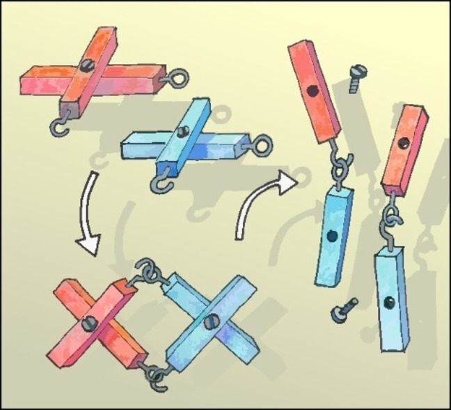
In the context of exploring and establishing a new fabrication method towards molecular textiles, molecular patches, which are smaller structural analogues, are investigated. The working principle of molecular patch formation, relies on a bi‐functional cross‐shaped covalent templated monomer, that via in‐solution synthesis forms macrocyclic oligomers, which upon template cleavage result into linear fragments.
Introduction
Interweaving structures is a craft humankind has mastered long ago, with as prime example the invention of textiles and fabrics. [1] These type of materials are indispensable in nowadays society due to the features they combine: flexibility and comfort with strength and endurability. [2] Mimicking interwoven materials on the molecular scale is a scientific challenge addressing intriguing questions like: “how do the advantageous macroscopic features translate to the nano‐scale level?” and even before that, ”how can we interweave molecular architectures in a controlled manner?”. [3]
Catenanes and rotaxanes were the first reported mechanically interlocked structures, resulting in the rapid exploration of a multitude of sophisticated frameworks.[ 4 , 5 , 6 , 7 , 8 ] The challenge in many of these thermodynamically controlled assemblies is to have access to suitable building blocks that combine dynamic features, pre‐organization as well as synthetic availability. It was found that many of the chemical designs use either supramolecular interactions or metal coordinated templates. Nevertheless, the first ever templated assembly of a catenane, reported by Schill and Lütringhaus, was done via a covalent templating strategy. [9] Even though metal coordinated building blocks have in many cases out‐performed covalent template strategies, there are a few examples of high‐yielding covalent template based approaches.[ 10 , 11 ]
A special class of molecular interwoven materials, as mentioned before, are molecular‐ textiles and fabrics. The simplest molecular textiles, consisting of two‐dimensional braided linear polymer chains, are a new class of 2D materials that have gotten some attention in the last years.[ 2 , 3 , 12 ] In this area of expertise there are some examples based on metal‐coordinated or supramolecular assembled structures.[ 13 , 14 , 15 ] However, there is no proven example of a fully organic covalent templating approach yet. In our recent work, we shared our new strategy for fabricating molecular textiles based on a cross‐shaped monomer that retains its conformation via a covalent template. [16] Assembly of this monomer on the air‐water interface, should yield a 2D cross‐linked network that is the precursor towards a molecular textile. Initial results have shown promising trends, but also classified characterization of this mono‐layer thick material, as extremely challenging. In order to build a well‐founded base for understanding the molecular structure and to fully comprehend the chemistry applied, we hypothesized about an in‐solution strategy towards molecular patches. In‐solution assembly of a textile cut‐out would allow to mimic the fabrication procedure of our target textile and in addition provide us with a small structural analogue. Thereby, the outcome of this investigation will provide us with essential information with regard to reactivity, synthetic strategy and helps us to pin‐point analysis.
In this work, we describe the synthesis of a fully‐organic cross‐shaped bi‐functional monomer that can be used to assemble molecular patches. This monomer, functionalized with a benzylic amine and aldehyde, can be used in wet‐chemistry set‐ups and can be analyzed with conventional organic synthesis analysis techniques. Furthermore, we report the in‐solution oligomerization via imine condensation as well as the on‐surface synthesis and characterization of linear and cyclic oligomers.
Results and Discussion
Design & Retrosynthesis
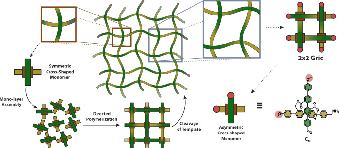
Our previous reported approach in the exploration of a new route towards molecular textiles is shown in the left side of Figure 1. Here, the monomers are cross‐shaped, consisting of a pair of rigid‐rod type structures as bars which are geometrically arranged by a covalent template. The control over both, the orientation of the cross‐shaped monomer at the air/water interface and the functional groups exposed at the ends of the bars should enable the formation of the molecular textile. Thereby, the monomers represent the cross‐over points of the textile and are assembled in a monolayer structure at the air/water interface. After template cleavage, the monolayer should yield in two perpendicular sets of parallel and periodically interwoven linear polymer strands: the molecular textile.
Figure 1.
left) Schematic illustration of bottom‐up approach of synthesizing a molecular textile utilizing the preorganization of a symmetric cross‐shaped monomer at the air‐water interface right) Schematic visualization of a cut‐out of the molecular textile (2×2 grid) and the molecular design of a bi‐functional asymmetric monomer CM that via imine condensation could assemble into cyclic oligomers.
To make the system more processible we focus on a structural analogue, namely the investigation of a cut‐out of the textile, e. g. 2×2 grid (depicted in purple). This pathway would allow to investigate the polymerization in wet chemistry, while characterizable by conventional analysis techniques like 1H‐NMR and IR. Additionally, it would allow to tackle pre‐mature processing challenges that we envision to do post mono‐layer assembly e. g. imine reduction or template cleavage. In addition, the molecular patch would be a semi‐interwoven resemblance of a textile, that could be investigated on mono‐layer scale to pin‐point structural and chemical characterization by e. g. atomic force microscopy (AFM). Figure 1, on the right section depicts the molecular design of an asymmetric analogue CM , of our early reported envisioned cross‐shaped monomers. Here, a terminus of each para‐quarterphenyl rod forming the cross‐shaped monomer is ‘blocked’ as an unreactive methoxy group, while the other end resembles the benzylic amine and aldehyde functionality intended for use in the imine condensation.
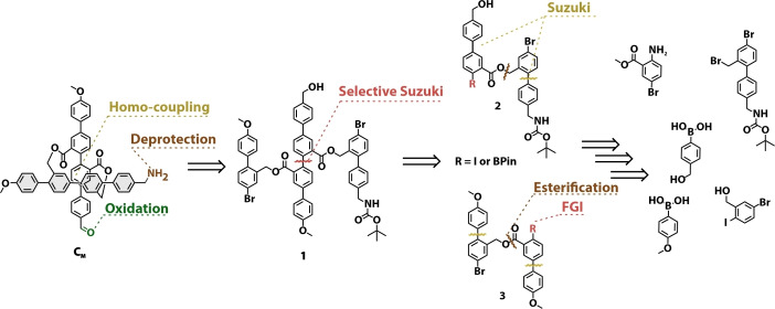
In Scheme 1, the retro‐synthetic analysis of bi‐functional asymmetric monomer CM is depicted. The target structure was envisioned to be obtained, similar to our reported strategy, in a late stage from 1 via an oxidative homo‐coupling macrocyclization followed by oxidation to the aldehyde and deprotection of the Boc‐group. Key intermediate 1, should be accessible via a selective Suzuki‐cross coupling reaction of precursor 2 and 3, profiting from the reactivity difference between an aryl‐iodine and an aryl‐bromine with regard to palladium catalyzed cross‐coupling chemistry. [17] Here, it was envisioned that either 2 or 3 could be selectively converted from an aryl‐iodide to a bis‐pinacolato borane via a Miyaura borylation. The building block 2, with the benzylic alcohol and masked amine functionality as well as 3 containing the methoxy groups could be assembled from similar precursors via series of well‐established reactions like Sandmeyer functional group conversion, Suzuki cross‐coupling reaction and esterification.
Scheme 1.
Retrosynthetic analysis: Assembly of asymmetric cross‐shaped monomer CM .
Synthesis
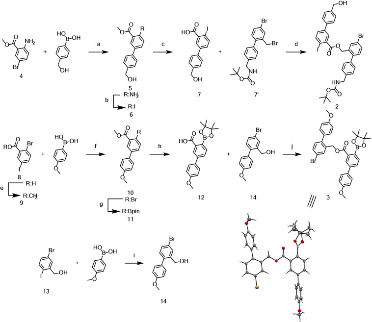
The synthesis of CM started with the assembly of intermediates 2 and 3, shown in Scheme 2. Building block 2 was obtained in 4 steps from 2‐amino 5‐bromo benzoate 4. First, 4 was reacted with [4‐(hydroxymethyl)phenyl]boronic acid in a Suzuki cross‐coupling reaction to obtain 5 in moderate yield. The amine was converted to iodide 6 in excellent yields (90 %), utilizing a Sandmeyer‐iodination with para‐toluene sulfonic acid (p‐TsOH), sodium nitrite (NaNO2) and potassium iodide (KI) in a mixture of acetonitrile (ACN) and water. Saponification of the ester yielded 7, which was reacted with previously reported 7’ in a cesium fluoride mediated substitution reaction to yield ester 2 in almost quantitative yield over two steps. [16] With 2 in hand the selective borylation of the aryl‐iodide was attempted, however this turned out to be unexpectedly challenging. Under a range of attempted Miyaura conditions, ranging from mild to harsher, there was almost no conversion or resulted in predominately dehalogenated products. Therefore, the strategy to assemble key intermediate 3 was slightly adapted by introducing the boronic ester in an earlier stage. Acid 8 was methyl‐protected via Fischer esterification, followed by a selective Suzuki‐cross coupling of 9 with [4‐(methoxy)phenyl]boronic acid to yield 10 in moderate yield. The aryl‐bromide was converted to boronic ester 11, via Miyaura‐borylation conditions with PdCl2(dppf), bis‐(pinacolato borane) (B2Pin2) and potassium acetate (KOAc) in dioxane at elevated temperature. Acid 12 was obtained quantitatively from 11 upon saponification with lithium hydroxide in a tetrahydrofuran water mixture. Benzylic alcohol 14 was obtained via a selective Suzuki cross‐coupling from (5‐bromo‐2‐iodophenyl)methanol 13 and successfully coupled to 12 via Steglich esterification utilizing dicyclohexyl carbodiimide (DCC) and 4‐dimethylaminopyridine (DMAP) yielding 3. The identity of 3 was corroborated by its solid‐state structure. Single crystals suitable for X‐ray analysis were obtained by slow evaporation of the solvent from a solution of 3 in CD2Cl2.
Scheme 2.
Synthesis of precursors 2 and 3. Conditions: a) Pd(PPh3)4; Na2CO3; Tol/MeOH/H2O (4 : 1 : 1.5); 80 °C; 5 h; 65 %. b) p‐TsOH; NaNO2; KI; ACN/H2O (3 : 1); 0 °C‐r.t.; 16 h; 90 %. c) NaOH; MeOH/H2O; reflux; 3 h; 98 %. d) 7’; CsF; DMF; r.t.; 16 h; 99 % e) H2SO4; MeOH; reflux; 4 h; 85 % f) PdCl2(dppf); K2CO3; DME/MeOH/H2O (4 : 1 : 1); 65 °C; 16 h; 71 %. g) PdCl2(dppf); B2Pin2; KOAc; dioxane; 90 °C; 6 h; 85 %. h) LiOH; THF/H2O; r.t.; 1 h; quant. i) PdCl2(dppf); K2CO3; DME/H2O (4 : 1); 60 °C; 3 h; 87 %. j) 14; DCC; DMAP; CH2Cl2/DMF; r.t.; 1.5 h; 44 %. Bottom‐right) Solid‐state structure of 3 plotted as ORTEP plots with 50 % probability.
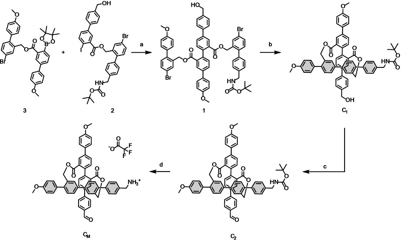
Scheme 3 shows how the previously prepared building blocks 2 and 3 were coupled via a selective Suzuki cross‐coupling at moderate temperature to yield key intermediate di‐bromide 1 in good yield. In a next step the bromines were converted to boronic esters via Miyaura borylation and the obtained crude was directly exposed to palladium mediated oxidative homo‐coupling conditions. This key macro‐cyclization step provided C1 in excellent yields (64 %) over both steps. By late stage modifications, C2 was obtained upon oxidation of the alcohol to the aldehyde by Dess‐Martin periodane (DMP), which was quantitatively converted to CM by exposure to trifluoroacetic acid (TFA) in dichloromethane. The target monomer CM was obtained as it's TFA‐salt after co‐evaporation of residual TFA with toluene. All compounds were accessible in good quality without excessive purification protocols and where characterized by 1H‐NMR, 13C‐NMR and HR‐ESI‐MS.
Scheme 3.
Synthesis of CM . Conditions: a) PdCl2(dppf); K2CO3; THF/H2O (4 : 1); 60 °C; 5 h; 82 %. b) i] PdCl2(dppf); B2Pin2; KOAc; dioxane; 90 °C; 4 h; ii] PdCl2(PPh3)2; THF/H2O (9 : 1); r.t.; 16 h; 64 % two steps. c)DMP; CH2Cl2; 0 °C‐r.t.; 2 h; 86 %; d) TFA; CH2Cl2; r.t.; 1 h; quant.
Physicochemical Analysis
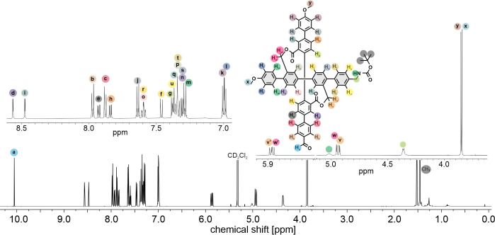
The 1H‐NMR analysis of final cross C2 displayed interesting features. First of all, it showed the formation of the rigid cross‐shape structure due to the presence of the diastereotopic protons observed before (Figure 2), which correspond to the benzylic ester protons. [16] Due to the lack of symmetry in C2 there are two sets of doublets for these protons (Hv and Hw). The dissymmetry is further displayed in the separation of almost equivalent protons, e. g. the two methoxy CH3 singlets of C2 , into two signals. Even though, this resulted in a quite distorted NMR spectrum, the majority of the peaks could be assigned to the corresponding protons by their chemical shifts and splitting as shown in Figure 2.
Figure 2.
1H‐NMR spectra of C2 in CD2Cl2 with assignment of the corresponding signals (600 mHz, 25 °C).
The identity of the cross‐shaped monomer was further corroborated by the solid‐state structure of C1 . Single crystals suitable for X‐ray analysis were obtained by slow vapor diffusion of heptane into a saturated solution of C1 in toluene. The solid‐state structure showed that C1 crystallizes as racemic mixture of both enantiomers, which arise from interlocking the axial twist of the di‐ester side of the molecule ((P)‐C1 is displayed in Figure 3). In the crystal packing each enantiomer is accompanied by one toluene molecule and the two quarterphenyl rods open an angle of 73°.
Figure 3.
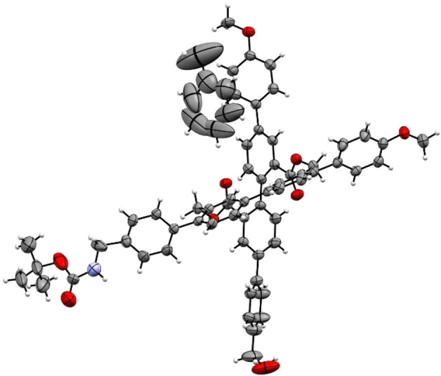
Solid‐state structure of cross (P)‐C1 , plotted as ORTEP plots with 50 % probability. Plotted as single enantiomer for clarity.
The racemic mixture was separated into its enantiomers on a chiral stationary phase HPLC (IG‐chiralpak, heptane/CH2Cl2: 40/60 v/v, supporting information Figure S4). The enantiomers were separated on analytical scale and circular dichroism (CD) measurements revealed that their spectra have perfect mirror image of the Cotton bands. DFT based simulation of the CD spectrum allowed to assign the first eluting sample as P‐ and the second eluting one as the M‐enantiomer (Supporting information Figures S5 and S6).
Oligomerization
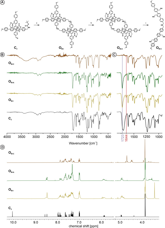
With the racemic monomer CM in hand we investigated the imine‐condensation based oligomerization (Figure 4A). Due to easier handling and improved storing stability of C2 in respect to CM , CM was freshly prepared prior to every oligomerization attempt via TFA mediated deprotection of the Boc group in dichloromethane. As we aimed for cyclic oligomers, the Schiff‐base condensation was performed under (pseudo)‐high dilution conditions favoring intra vs. inter molecular reactions. The outcome of imine based covalent organic framework synthesis has been reported to depend strongly on reaction conditions like e. g. temperature and solvent.[ 18 , 19 , 20 , 21 ] Therefore, three different conditions, altering solvent, temperature and base were investigated.
Figure 4.
A) Synthesis scheme of imine condensation, reduction and template removal. Conditions a) i. TFA; CH2Cl2; r.t.; 1 h; ii) [c] 1 mmol/L; Na2CO3; CH2Cl2; r.t.; 24 h or TEA; THF; r.t.; 24 h; or TEA; CHCl3; 60 °C; 24 h; b) NaBH(OAc)3; B(OH)3; CHCl3; r.t.; 4 h; c) LiAlH4; THF; 0 °C‐r.t.; 2 h. B,C) FT‐IR (neat) and D) 1H‐NMR (CD2Cl2, r.t.) analysis of C2 , OM‐I , OM‐A , OM‐C , showing the appearance and disappearance of the characteristic signals corresponding to functional groups imine (1644 cm−1; 8.5 and 4.84 ppm), ester (1723 cm−1; 5.8 and 4.95 ppm), aldehyde (1697 cm−1, 10.2 ppm), benzylic alcohol (−C H 2 OH) (4.68; 4.45 ppm).
As already reported for the fourfold functionalized molecular cross model compound, the Schiff‐base condensation could simply be triggered by deprotonation of the benzylic ammonium. [16] In an initial attempt CM was dissolved in a 100/1 CH2Cl2/TFA mixture and dropwise added to a suspension of sodium carbonate in CH2Cl2. Monitoring the reaction by matrix‐assisted laser desorption‐ionization mass spectrometry (MALDI‐MS) displayed the gradual formation of dimeric, trimeric and tetrameric oligomers within the first 30 min (Supporting information, Figure S7), while after 20 h solely one peak at 1646 m/z was observed, pointing at the cyclic dimer as thermodynamically favored species. Very similar dynamic in the formation of oligomers was observed by MALDI‐MS for adapted conditions using triethylamine (TEA) as base either in dry‐tetrahydrofuran (THF) at room temperature (condition 2) or in chloroform (CHCl3) at elevated temperature (condition 3). However, due to the absence of solid Na2CO3, conditions 2 and 3 enabled to observe that the initially transparent solutions turned turbid indicating the precipitation of material. The reaction product OM‐I was analyzed by Fourier transform infrared spectroscopy (FT‐IR) and 1H‐NMR. The FT‐IR spectrum of OM‐I is displayed in Figure 4B, and parts of it expanded in Figure 4C. A new peak at 1644 cm−1, highlighted by a red line in the background of Figure 4C, is characteristic for the C=N imine stretch vibration. The comparison with the FTIR spectrum of C2 shows the disappearance of the broad signals at about 1700 cm−1 from the carbonyl (C=O) stretch vibration of the aldehyde and Boc protection group. Furthermore, the carbonyl vibration at 1723 cm−1, which can be assigned to the ester, remains, pointing at almost full conversion of the monomer to oligoimine. This was further corroborated by 1H‐NMR analysis of OM‐I in CD2Cl2. The spectrum revealed that there was almost no residual aldehyde or amine protons (Figure 4D), while new peaks arise at 4.84 and 8.50 ppm corresponding to the chemical shift of the benzylic protons and the formed imine proton respectively. To gain more information about the distribution of the oligoimine mixture or about the dimension of the formed cyclic oligoimine respectively, 1H‐NMR Diffusion Ordered Spectroscopy (DOSY) was performed. The OM‐I mixture indicated a single higher order species with a diffusion coefficient of 7.703⋅10−10 m2/s in CD2Cl2 at 25 °C (Supporting information, Figure S8). Comparison to the diffusion coefficient of C2 (D=9.52⋅10−10 m2/s) indicated that the molecular weight ratio of OM‐I/C2 equals 1.93 suggesting a dimeric structure. The interpretation was further supported by, HR‐ESI‐MS analysis displaying exclusively a signal of the cyclic‐dimeric imine species. While the dissolved species was identified as the cyclic dimer, it is noteworthy that the solubility of the system is at the edge. Thus, a possible hypothesis for the observation of only the smallest molecular patch could be a very limiting poor solubility of larger oligomeric species. In other words, the formed higher order oligomers might not be soluble enough to be detected in the DOSY experiment as well as HR‐ESI‐MS. However, a variety of imine‐based covalent organic architectures have been reported to form the smallest possible cyclic structure as the thermodynamically most stable compound.[ 22 , 23 , 24 ] Thus the formation of the cyclic imine dimer is in line with these results and just complements the already existing examples.
To improve the stability of the cyclic oligomers, the reduction of the imines to the more stable amines was considered. A variety of conditions were attempted using either ethanol or methanol as proton source, resulting in non or poor conversion. A better suited method was found by adapting a solid‐state procedure of Cho et al., where they used boric acid as proton source in the presence of sodium borohydride NaBH4. [25] Instead of the required grinding we found that this reaction performs very well in CHCl3 with sodium borohydride triacetoxy (NaBH(OAc)3 as reducing agent, resulting in full conversion after 4 h of OM‐I to OM‐A . The transformation was indicated by the disappearance of the FT‐IR signal at 1644 cm−1 (Figure 4B and C) and can also be observed in the 1H‐NMR spectra of the compounds (Figure 4D). However, overlapping signals reduce to some extent the visibility. The multiplet of OM‐I at 4.84 ppm is from the benzylic protons attached to the imine nitrogen and shift upon reduction to OM‐A to 3.7–3.9 ppm, where they overlap with the methoxy protons. In the same region are the benzylic protons formed upon the reduction of the imine group, from which the proton disappears at about 8.5 ppm, where it overlapped with signals from the quarterphenyls. Comparing the ratio of the integrated signals (Supporting info, Figure S9) shows that the combined methoxy and benzylic amine peak integrates to twenty in comparison to respective four and four for the benzylic ester protons of the cross structure, matching the expected ratio for a dimer as well as higher order cyclic oligomers. To further verify the attribution of the signals to their respective protons we compared the 1H‐NMR of model compounds I and A, which are provided in supporting information Figure S10. Here I and A, showed similar chemical shifts in the assigned regions for the imine proton, as well as the CH2 protons of the benzylic‐ imine and amine respectively, corroborating our assignment. Analysis of OM‐A via HR‐ESI‐MS revealed again the presence of the dimeric patch as most intense main peak. However, also the mass signals of cyclic trimeric as well as tetrameric species could be identified. Even though their intensities were several orders of magnitude lower than the dimer signal, it showed that there are several molecular patches present at least in trace. Again, it is noteworthy that the reduction to OM‐A also resulted in a slightly higher solubility, such that this might also support the sudden visibility of (in traces) present higher cyclic oligomers by the analytical techniques.
The improved stability of the amine and the identification of higher order oligomers by mass spectrometry motivated attempts to isolate distinct sizes of molecular patches. However, neither, silica column chromatography, size exclusion chromatography (SEC) or high‐performance liquid chromatography was successful. In all attempts, either multiple species eluted simultaneously or the species displayed extreme smearing as illustrated by the SEC chromatogram (Supporting information, Figure S11). Once again, the behavior is characteristic for macromolecules with low solubility such that the analysis of the composition of the cyclic oligomers is to some extent handicapped by the most likely varying solubility of the different sized oligomers. However, based on the analytical data, the main component in solution is the macrocyclic dimer.
Even so the separation of the cyclic oligomer OM‐A into individual components failed, we moved forward to the final proof of concept step. The cross‐shaped target structure has been developed with the intention to be able to divide it into the two bars that are forming it. Interestingly, upon cleavage of the interlinking ester bridges the formed structure OM‐C consisting of a pair of amine interlinked quarterphenyl bars remains the same irrelevant of the dimensions of the cyclic oligomer OM‐A . To cleave the two ester bridges interconnecting the two quarterphenyl bars to the cross, OM‐A was exposed to lithium aluminum hydride (LiAlH4) in anhydrous THF to provide OM‐C . The transformation was once again clearly visible in the FT‐IR analysis of the reaction product, which showed the complete vanishing of the carbonyl signal, while the OH vibration (3300 cm−1) of the benzylic alcohols appears. In the 1H‐NMR of OM‐C the absence of the characteristic diastereatopic protons of the center motive documented the cleavage of the template, while two new peaks arise at 4.45 ppm and 4.68 ppm which can be attributed to the benzylic CH2 groups neighboring the alcohols. Here, the most up‐field shifted signal can be attributed to the benzylic position formed from the former acid, which due to steric clash appears as a multiplet. Therefore, the more downfield shifted protons were assigned to the other benzylic pair.
In spite of the unsolved challenges to separate the individual cyclic oligomers, the formation of the final species, the interlinked bars OM‐C , which was characterized by 1H‐NMR, 2D‐NMR and HRMS, after isolation via silica column chromatography, corroborates the success of the series of intended transformations: namely; the condensation to cyclic oligoimines, their reduction to cyclic oligoamines, and the template cleavage (Supporting information, page S111–S116).
On‐surface Synthesis
The intention behind the cross‐shaped monomer is to form extended monolayers by self‐assembling at the flat air/water interface. An interesting question was thus the behavior of the bifunctional cross‐shaped monomer CM on a planar 2D support. And indeed, our initial hope to be able to resolve the molecular shape in such an experiment were even excelled. To study CM on a surface, a high vacuum electrospray deposition (HV‐ESD) was performed.[ 26 , 27 ] The monomer was deposited on an Au(111) surface maintained at room temperature from a CH2Cl2/TFA (99/1) solution. Non‐contact atomic force microscopy (nc‐AFM) was used to confirm the successful deposition (Supporting information, Figure S12). The large scale topography image reveals the presence of CM concentrated around the step‐edges, clusters or small chains of CM and remaining solvent molecules aligned at the herringbone kinks. However, the resolution of the sub molecular image did not allow to clearly identify the subunits of CM .
With the intention to remove residual solvent molecules, the substrate was annealed at 110 °C for 20 min. Upon that treatment, the majority of the individual monomers previously spread on the surface, started to coalesce in assemblies of longer linear oligomeric structures (displayed in Figure 5A), which was interpreted as the on‐surface imine condensation of CM to OM‐I . As visible in the topography of Figure 5A, extended linear structures are identified, with lengths up to 50 nm. It thus seems that the annealing under high vacuum favors the imine formation, probably pushing the condensation to its product by removal of the water molecules. The herringbone Au(111) surface reconstruction, visible together with the molecules (Supporting information, Figure S13), is a good indication of a clean surface after the removal of the solvent molecules.
Figure 5.
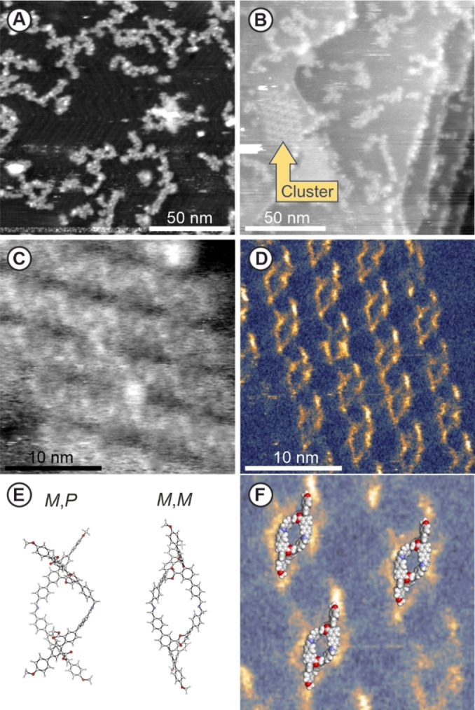
NcAFM images on electrospray deposited CM , on an Au(111) surface after annealing at 110 °C. A) Topography image showing linear polymeric structures and herringbone reconstruction of the gold surface B) Topography image, showing a highly organized cluster (mid‐left). C) Topography and corresponding D) excitation of second eigenmode resonance on the cluster showing a repetitive pattern fitting the rhomboid shaped optimized geometry of (M,P)/(M,M)‐OM‐I‐dimer in vacuo (BL3YP/6‐31G(D) & BL3YP/6‐21G) (E). F) (M,M)‐OM‐I‐dimer overlaid with zoom in of the cluster. parameters: f1 = 322 kHz. A) A1 = 5nm, Δf1 = ‐100 Hz. B) A1 = 3nm, Δf1 = ‐50 Hz. C,D) A1 = 8nm, Δf1 = ‐60 Hz, f2 = 2.3 MHz, A2 = 200pm.
Within the linear structures of various dimensions and shapes, also a cluster of highly ordered rhomboid shaped structures was observed (left side of Figure 5B). The zoomed second eigenmode topography on the cluster (Figure 5C) disclosed parallel rows in the substructure of the cluster. With the help of the simultaneously acquired dissipation image the cluster was resolved in more details, as shown in Figure 5D. Additional signals are visible in the supporting information Figure S14 to help to identify the cluster. We attribute the higher dissipative area to the skeleton of the molecules. The dissipation image shows the distortion in the rhombic structure where one corner is clearly pointing more out of plane, as well as that it seems to have a semi spiral like alignment on the surface. This advocates for the successful synthesis of cyclic dimer OM‐I‐dimer .
The resolution of the excitation image (Figure 5D) even allowed to further identify the character of the formed macrocyclicoligoimine dimer OM‐I‐dimer . In Figure 5E the geometry optimized structures of two possible dimers are displayed, namely the (M,M)‐OM‐I‐dimer as representative of a homochiral dimer made of enantiopure monomers, and (M,P)‐OM‐I‐dimer as the meso form combining the enantiomers of different chirality. In Figure 5F, the M,M‐dimer is overlaid with a zoom on the dissipation image of the rhombic structure, displaying pronounced structural as well as dimensional similarity. While the match of the structures suggest that the island consists exclusively of homochiral dimers, it does not allow to distinguish between M,M‐ and P,P‐dimers. Most likely both homochiral dimers are present in comparable amounts. Even though the in vacuum optimized structures don't consider the surface influence, the similarity corroborates the assembly of cyclic dimeric structures on the Au(111) surface.
The successful deposition of the monomer and its on‐surface condensation to oligoimines monitored and identified by HV‐ESD and nc‐AFM respectively, demonstrated both, the power and the potential of this technique. For our future plans, it allows to deposit monomers we intend to use for our molecular textile prematurely and to investigate its chemical behavior as well as structural features. In particular, the initiation of the imine condensation upon annealing might open new pathways towards the assembly of our intended 2D‐structure. Thus, the combination of these techniques became very interesting tool to scout for suitable monomers and to investigate their condensation behavior, with potential similarities to the self‐assembly and condensation behavior on the air/water interface.
Conclusion and Outlook
In the context of assembling a molecular textile, an in‐solution strategy for the fabrication of molecular patches is presented. A bi‐functional cross‐shaped monomer CM is developed, comprising as functional termini an aldehyde and a benzylic amine. Via 1H‐NMR and X‐ray structure analysis the identity of the monomer is corroborated as racemic mixture. The dimeric patch is obtained as main cyclic oligomer upon exposing the monomer to Schiff‐base condensation conditions. Reversibility of the system is eliminated by reduction to the cyclic amines OM‐A . The crosses are divided into individual bars upon subsequent template cleavage transforming the cyclic amines into pairs of amine interlinked bars OM‐C . The success of the in‐solution strategy corroborates the intended supramolecular function, the liberation of the covalently interlinked bars forming the crosses upon a chemical trigger.
Additionally, the monomer is exposed to a flat Au (111) surface via high vacuum electrospray deposition. On‐surface imine condensation is achieved by annealing, resulting in the assembly of linear oligomers and a cluster of homochiral dimers. The structural identity of the dimeric patch is analyzed via nc‐AFM, and excellent shape match with the calculated structures of a homochiral imine dimer (M,M)‐OM‐I‐dimer is observed.
The findings not only show the potential of the cross architecture as covalently templated supramolecular synthon, but also provide an excellent fundament to benchmark the chemistry required to master the formation of molecular textiles. The established protocols and analysis methods are crucial in our‐pursuit for the assembly of our desired mechanically interwoven 2D‐material.
Experimental Section
General
All chemicals and solvents were purchased from Sigma Aldrich, Acros, Apollo Scientific, Alfa Aesar and Fluorochem and used as received. NMR solvents were obtained from CIL Cambridge Isotope Laboratories, Inc., Acros, Sigma‐Aldrich, or Apollo Scientific. Dry solvents were used as crown capped and purchased from Acros and Sigma‐Aldrich. Column chromategraphy was performed manually or on a Biotage Isolera using SilicaFlashR P60 from Silicycle with particle size of 40–63 μm (230–400 mesh) as stationary phase.TLC was performed with silica gel 60 F254 glass plates purchased from Merck. NMR experiments were performed on Bruker Avance III NMR spectrometers operating at 250, 400, 500 or 600 MHz proton frequencies. The instruments were equipped with a direct‐observe 5 mm BBFO smart probe (250, 400 MHz), or an indirect‐detection 5 mm BBI probe (500, 600 MHz) NMR. All probes were equipped with actively shielded z‐gradients (10 A). The chemical shifts are reported in ppm relative to TMS or referenced to residual solvent peak and the J values are given in Hz. Infrared spectra were recorded neat with an ATR equipped Schimadzu IRTacer‐100. High‐resolution mass spectra (HR‐MS) were measured with a Bruker Maxis 4G ESI‐TOF instrument. CD measurements were performed on a JASCO J‐1500 CD Spectrophotometer in a 1 cm quartz glass cuvette. For analytical HPLC, a Shimadzu LC‐20AT HPLC was used, equipped with a diode‐array UV/Vis detector (SPD−M20 A VP from Shimadzu, λ=200–600 nm) and a column oven Shimadzu CTO‐20AC. The used column for analytical separation on chiral stationary phase was a Chiralpak IG, 5 μm, 4.6×250 mm, Daicel Chemical Industries Ltd.
Synthetic Procedures
Di‐bromide 1: A 25 mL Schlenk tube was charged with boronic ester 3 (165 mg, 1 equiv.). iodine 2 (182 mg, 1 equiv.) and K2CO3 (104 mg, 3 equiv.). The solids were dispersed in a 10 mL THF/H2O (4 : 1; v/v) mixture. The resulting suspension was degassed with argon followed by the addition of PdCl2(dppf) (14 mg, 7 mol %). The mixture was heated at 60 °C for 5 h before cooled down to room temperature and filtered over a silica pad. The silica pad was flushed down with EtOAc and the filtrate was washed with H2O. The organic layer was collected, dried with sodium sulfate and concentrated before subjected to Silica column chromatography using Cyclohexane:EtOAc (8 : 2 to 7 : 3; v/v) as eluent. The product was obtained as a white solid (222 mg, 82 %) after stripping of the volatiles.
1H‐NMR: (500 MHz, CD2Cl2): δ 8.10–8.09 (m, 1H), 8.07 (s, 1H), 7.72–7.64 (m, 2H), 7.61–7.57 (m, 2H), 7.57–7.53 (m, 2H), 7.51–7.46 (m, 2H), 7.37–7.19 (m, 8H), 7.16–7.11 (m, 2H), 7.10–7.06 (m, 2H), 7.04–6.98 (m, 4H), 6.87–6.83 (m, 2H), 4.99–4.95 (m, 4H), 4.92 (s, 1H), 4.75 (s, 2H), 4.24 (d, J=6.0 Hz, 2H), 3.87 (s, 3H), 3.76 (s, 3H), 1.92 (s, 1H), 1.44 (s, 9H). 13C‐NMR {1H}: (126 MHz, CD2Cl2): δ 167.14, 167.00, 160.10, 159.64, 142.05, 140.92, 139.95, 139.22, 139.19, 138.94, 138.48, 135.34, 132.65, 132.58, 132.12, 131.96, 131.91, 131.74, 131.53, 131.45, 131.40, 131.30, 130.49, 130.32, 130.30, 130.12, 129.68, 129.51, 128.82, 128.47, 128.33, 127.76, 127.73, 127.51, 121.51, 121.11, 114.62, 114.13, 79.73, 65.14, 64.50, 64.44, 55.75, 55.64, 28.53. HR‐ESI‐MS (+): m/z calculated for C61H53Br2NO9Na [M+Na]+; 1124.1979 found 1124.1987.
Cross C1 : Dibromo 1 (210 mg, 0.19 mmol, 1 equiv.), B2Pin2 (117 mg, 0.46 mmol, 2.4 equiv.) and KOAc (112 mg, 1.14 mmol, 6 equiv.) were loaded into a 25 mL flame‐dried Schlenk tube and cycled between vacuum and argon 3 times. Dry Dioxane (6 mL) was added and the mixture was degassed with argon for 15 min. PdCl2(dppf) (18 mg, 0.02 mmol, 0.1 equiv.) was added and the mixture was heated to 90 °C. The reaction was tracked via LC–MS and after full consumption (3 h) of the starting material the reaction was cooled down to room temperature, filtered over a silica pad, flushed down with EtOAc and concentrated under reduced pressure. The concentrate was dissolved in 100 mL THF, followed by the addition of PdCl2(PPh3)2 (67 mg, 0.095 mmol, 0.5 equiv.) and boric acid (59 mg, 0.95 mmol, 5 equiv.). The mixture was stirred vigorously for 15 min before KF (114 mg, 1.9 mmol, 10 equiv.) dissolved in 10 mL H2O was added in one portion. The mixture was stirred for 16 h at room temperature open to the atmosphere, before it was filtered over silica and flushed down with THF. Organic volatiles were removed under reduced pressure and the remaining aqueous phase was extracted with EtOAc 3 times. The organic phases were combined, dried with sodium sulphate and concentrated under reduced pressure. The crude was purified by SiO2 column chromatography using Cyclohexane and EtOAc as eluent, collecting the 2nd band. The obtained yellowish solid was dispersed in MeOH and the white precipitate was collected by filtration and dried, yielding the desired compound C1 as an off‐white solid (115 mg, 64 % over two steps).
1H‐NMR: (500 MHz, CD2Cl2): δ 8.51 (d, J=2.0 Hz, 1H), 8.47 (d, J=2.0 Hz, 1H), 7.87 (dd, J=8.0, 2.0 Hz, 1H), 7.83 (dd, J=8.0, 2.1 Hz, 1H), 7.72–7.67 (m, 2H), 7.66–7.62 (m, 2H), 7.61–7.56 (m, 2H), 7.46 (d, J=8.3 Hz, 2H), 7.41 (d, J=8.0 Hz, 1H), 7.39–7.28 (m, 11H), 7.02–6.97 (m, 4H), 5.89–5.84 (m, 2H), 5.03 (s, 1H), 4.94 (d, J=9.1 Hz, 1H), 4.91 (d, J=9.0 Hz, 1H), 4.74–4.70 (m, 2H), 4.36 (d, J=6.1 Hz, 2H), 3.85 (s, 3H), 3.84 (s, 3H), 1.87 (s, 1H), 1.46 (s, 9H). 13C‐NMR {1H}: (126 MHz, CD2Cl2): δ 166.29, 166.17, 160.03, 159.61, 156.27 144.77, 143.92, 141.29, 140.09, 140.06, 139.67, 139.31, 139.24, 139.20, 139.08, 139.04, 134.97, 134.87, 132.55, 132.36, 132.19, 132.04, 130.73, 130.64, 130.56, 130.27, 129.63, 129.61, 129.19, 128.48, 127.82, 127.71, 127.49, 125.92, 124.87, 124.82, 114.69, 114.24, 79.65, 65.10, 64.11, 64.03, 55.71, 44.59, 28.54. HR‐ESI‐MS (+): m/z calculated for C61H53NO9Na [M+Na]+; 966.3603 found 966.3603.
Cross C2 : Cross C1 (60 mg, 0.064 mmol, 1 equiv.) was dissolved in dry dichloromethane (6 mL) and cooled down to 0 °C. DMP (33 mg, 1.2 equiv.) was added portion wise while cooled and after full addition the mixture was allowed to warm to room‐temperature. The mixture was tracked by TLC and upon full conversion after 1 h the mixture was quenched with sat. NaHCO3 and sat. NaHSO3. The aqueous phase was extracted with CH2Cl2 3 times and concentrated. The crude was plugged over a pad of silica (CH2Cl2:EtOAc 9 : 1) yielding the product as a white solid (52 mg, 86 %).
1H‐NMR: (500 MHz, CD2Cl2) δ 10.05 (s, 1H), 8.57 (d, J=2.0 Hz, 1H), 8.48 (d, J=2.1 Hz, 1H), 7.97 (d, J=8.1 Hz, 2H), 7.92 (dd, J=8.0, 2.0 Hz, 1H), 7.88 (d, J=8.2 Hz, 2H), 7.84 (dd, J=8.0, 2.0 Hz, 1H), 7.66–7.62 (m, 2H), 7.60 (ddd, J=8.1, 6.6, 1.9 Hz, 2H), 7.46 (d, J=8.0 Hz, 1H), 7.40–7.27 (m, 12H), 7.03–6.97 (m, 4H), 5.87 (dd, J=14.1, 7.9 Hz, 2H), 5.03 (s, 1H), 4.94 (dd, J=14.1, 3.4 Hz, 2H), 4.36 (d, J=6.2 Hz, 2H), 3.85 (s, 3H), 3.84 (s, 2H), 1.46 (s, 9H). 13C‐NMR {1H}: (126 MHz, CD2Cl2) δ 192.11, 166.30, 165.94, 160.06, 159.62, 145.99, 143.60, 140.25, 139.65, 139.24, 139.21, 139.12, 138.99, 138.98, 136.05, 134.94, 134.79, 132.48, 132.43, 132.33, 131.88, 130.90, 130.75, 130.68, 130.60, 130.56, 130.33, 130.05, 129.63, 129.23, 128.48, 128.08, 128.05, 127.72, 127.64, 125.90, 124.91, 124.86, 114.71, 114.25, 79.78, 64.15, 64.12, 55.72, 44.58, 28.54. HR‐ESI‐MS (+): m/z calculated for C61H51NO9Na [M+Na]+; 964.3456 found 964.3455.
Monomer CM : Cross C2 (24 mg, 1 equiv.) was dissolved in 1 mL CH2Cl2 and 0.1 mL TFA was added, the mixture is stirred for 1 h. 5 mL toluene was added and the mixture was concentrated under reduced pressure yielding the product as the TFA salt (25 mg, quant.) as an off‐white solid. Reaction in NMR‐Tube: 3 mg of cross C2 was dissolved in 0.75 mL CD2Cl2 followed by the addition of 70 μL TFA‐d. The tube was shaken until homogenous and 1H‐NMR spectra were recorded after several time intervals. After 1 h the spectra indicated full conversion towards the product.
1H NMR (600 MHz, CD2Cl2:TFA‐d 10 : 1) δ 9.98 (s, 1H), 8.60 (d, J=2.0 Hz, 1H), 8.53 (d, J=2.0 Hz, 1H), 8.11–8.06 (m, 2H), 7.97 (dd, J=8.0, 2.0 Hz, 1H), 7.92–7.86 (m, 3H), 7.67–7.58 (m, 4H), 7.54–7.39 (m, 6H), 7.34–7.26 (m, 6H), 7.09–7.03 (m, 4H), 5.84 (d, J=14.4 Hz, 2H), 5.08 (d, J=14.4 Hz, 1H), 5.00 (d, J=14.4 Hz, 1H), 4.40 (s, 2H), 3.94 (s, 3H), 3.93 (s, 3H).
1H‐NMR: (500 MHz, DMSO‐d6): δ 10.07 (s, 1H), 8.54 (d, J=2.1 Hz, 1H), 8.42 (d, J=2.1 Hz, 1H), 8.22 (s, 3H), 8.11 (dd, J=8.1, 2.1 Hz, 1H), 8.06–7.99 (m, 4H), 7.96 (dd, J=8.1, 2.1 Hz, 1H), 7.75–7.67 (m, 4H), 7.60–7.56 (m, 2H), 7.55–7.48 (m, 3H), 7.40 (d, J=8.0 Hz, 1H), 7.38–7.32 (m, 4H), 7.25–7.18 (m, 2H), 7.09–7.03 (m, 4H), 5.77 (dd, J=14.6, 8.5 Hz, 2H), 5.00 (dd, J=14.4, 5.4 Hz, 2H), 4.16–4.09 (m, 2H), 3.81 (d, J=5.1 Hz, 6H).
13C‐NMR {1H}: (126 MHz, DMSO‐d6): δ 192.76, 165.11, 164.85, 159.31, 158.84, 144.91, 144.34, 142.61, 139.15, 139.09, 137.83, 135.44, 134.20, 134.07, 131.01, 130.54, 130.28, 130.06, 129.16, 129.09, 127.87, 127.46, 127.03, 126.71, 124.74, 124.04, 114.56, 114.03, 63.92, 55.21, 55.19, 42.01. Signals: 192.76, 165.11, 164.85, 159.31, 144.91, 144.34, 142.61, 139.15, 139.09, 137.83, 134.20, 134.07, 131.01, 130.54, 127.03, 126.71, 124.74, 124.04, 63.92 are extracted from 2D‐NMR. HR‐ESI‐MS (+): m/z calculated for C56H44NO7 [M+H]+; 842.3112, found 842.3120.
Synthesis of 2 and 3 are reported in the supporting information.
OligomerizationImine Condensation OM‐I
tlsb=0%Procedure 1: CM (1 equiv.) was dissolved in CH2Cl2:TFA (1 mmol/mL) and dropwise added to a dispersion of Na2CO3 (10 equiv.) in CH2Cl2. After full addition the mixture was allowed to stir for 24 h before the mixture was filtered over cotton and the filtrate was concentrated under reduced pressure, obtaining OM‐I .
Procedure 2: CM (1 equiv.) was dissolved in dry‐THF (1 mmol/L) and the mixture was stirred for 1 h at room‐temperature. TEA (2 equiv.) was added and the resulting mixture was stirred for an additional 16 h. The volatiles were removed under reduced pressure and the solids were triturated with MeOH (3 times) to obtain OM‐I .
Procedure 3: CM (1 equiv.) was dissolved in chloroform (1 mmol/mL) and the mixture was heated to 60 °C. Then TEA (2 equiv.) was added and the resulting mixture was stirred at 60 °C for 16 h. After cooling down MeOH (20 mL) was added and the insoluble OM‐I were collected via filtration. The solids were washed with an additional portion of MeOH.
Reduction OM‐A : OM‐I (1 equiv., calculated from CM step 1), ground B(OH)3 (20 equiv.) and NaBH(OAc)3 (20 equiv.) were added to a round‐bottom flask. Chloroform (5 mmol/L) was added and the resulting suspension was stirred for 4 h. The reaction was quenched with sat. NaHCO3 and the mixture was concentrated under reduce pressure. The solids were washed with water 3 times followed by MeOH, obtaining OM‐A as the remaining solid.
Template cleavage OM‐C: OM‐A (5 mg) was dissolved in 2 mL dry‐THF under argon atmosphere. The mixture was cooled before 1 M LiAlH4 in THF (0.02 mL, 5 equiv.) was added carefully. The mixture was allowed to heat to room temperature and stirred for 3 h. The mixture was cooled on ice before it was quenched with some drops of water. The mixture was diluted with chloroform and excess Na2SO4 was added. The suspension was filtered of and the filtrate was concentrated. The crude was subjected to silica gel column chromatography (CH2Cl2:MeOH 93 : 7→9 : 1) collecting OM‐C as a white solid (1.2 mg, 22 %). 1H NMR (500 MHz, THF): δ 7.98 (dd, J=8.8, 1.7 Hz, 2H), 7.90 (dd, J=6.2, 1.7 Hz, 1H), 7.85 (d, J=1.7 Hz, 1H), 7.69–7.66 (m, 2H), 7.65–7.60 (m, 4H), 7.57 (dd, J=7.8, 2.0 Hz, 1H), 7.53–7.45 (m, 4H), 7.44–7.39 (m, 2H), 7.38–7.35 (m, 2H), 7.32 (d, J=7.9 Hz, 1H), 7.30 (d, J=7.9 Hz, 1H), 7.17 (ddd, J=11.4, 7.8, 4.0 Hz, 2H), 7.04–6.94 (m, 4H), 4.58 (dd, J=9.0, 5.4 Hz, 4H), 4.37 (q, J=4.8 Hz, 4H), 4.18 (tt, J=9.6, 5.4 Hz, 4H), 3.89 (d, J=3.9 Hz, 4H), 3.82 (d, J=1.1 Hz, 6H). 13C‐NMR (126 MHz, THF): (C‐adjacent to H, subtracted from HMQC) δ 130.08, 129.88, 129.86, 129.71, 129.58, 129.30, 129.20, 128.55, 127.67, 127.59, 126.75, 126.45, 126.36, 126.00, 125.63, 124.86, 124.64, 124.30, 113.94, 113.30, 61.64, 61.38, 54.15, 52.50. HR‐ESI‐MS (+): m/z calculated for C56H52NO6 [M+H]+; 834.3789, found 834.3796.
High Vacuum Electrospray Deposition
The electrospray deposition is performed on samples kept at room temperature in ultra high vacuum conditions using a modified commercial system from molecular‐spray, as already explained in.[ 26 , 27 , 28 , 29 , 30 ] The CM molecules are dissolved in a CH2Cl2/TFA mixture (ratio 99/1). During the spray deposition, the pressure rose up to 5.0×10⁻⁸ mbar. Typical applied voltage is 1.2 kV for 10 min.
Au(111) Sample Preparation
Au(111) single crystal (Mateck GmbH) are prepared in UHV conditions with several cycles of Ar+ sputtering and annealing at 750 K. Surfaces are imaged after clean preparation and herringbone reconstruction is observed for all surfaces.
Room Temperature ncAFM
Room temperature ncAFM measurement are performed with a home built non contact atomic force microscope operated with a Nanonis electronic RC4.5. PPP‐QNCHR cantilevers (Nanosensor) are used as sensor (typical resonance frequencies of f1=320 kHz, f2=2,3 MHz and oscillation amplitudes A1=2–10 nm, A2=200 pm for first and second eigenmode respectively). Cantilever preparation consisted of an annealing for 1 h at 400 K followed by Ar+ sputtering for 90 s at 700 eV. During experiments, the base pressure of the UHV system was 2.0×10⁻¹¹ mbar. Data are analyzed using the Gwyddion software. [31]
Supporting Information Summary
The Supporting Information comprises the synthetic protocols and the characterization of the compounds, physicochemical analyses, oligomerization protocols and analyses including simpler model compounds detailed, geometry optimization and characterization and crystallographic data. Deposition Numbers 2371751 (3) and 2374177 (C1 ) contain the supplementary crystallographic data. These data are provided free of charge by the joint Cambridge Crystallographic Data Centre and Fachinformationszentrum Karlsruhe Access Structures service. The authors have cited references within the Supporting Information.
Conflict of Interests
The authors declare no conflict of interest.
1.
Supporting information
As a service to our authors and readers, this journal provides supporting information supplied by the authors. Such materials are peer reviewed and may be re‐organized for online delivery, but are not copy‐edited or typeset. Technical support issues arising from supporting information (other than missing files) should be addressed to the authors.
Supporting Information
Acknowledgments
Generous support from the Swiss National Science Foundation (SNF) is acknowledged (A.H., G.N‐M, and E.M. for project No. 200021‐228403; C.C.E.K, A.D'A, and M.M. for project No.200020_207744). A.H., G.N−M, and E.M. thank the Swiss Nanoscience Institute (SNI). M.M. acknowledges support from the 111 project (Grant No. 90002‐18011002). The authors are thankful for open access funding provided by the Universität Basel. Open Access funding provided by Universität Basel.
In memory of the pioneer of covalent templating Prof. Dr. Gottfried Schill
Kroonen C. C. E., Hinaut A., D'Addio A., Prescimone A., Häussinger D., Navarro-Marín G., Fuhr O., Fenske D., Meyer E., Mayor M., Chem. Eur. J. 2024, 30, e202402866. 10.1002/chem.202402866
Data Availability Statement
The data that support the findings of this study are available in the supplementary material of this article.
References
- 1.S. Seema, Textbook of Fabric Science, Fourth Edition: Fundamentals to Finishing, PHI Learning Pvt. Ltd. 2022, New Delhi .
- 2. Di Silvestro A., Mayor M., Chimia 2019, 73, 455. [DOI] [PubMed] [Google Scholar]
- 3. Zhang Z.-H., Andreassen B. J., August D. P., Leigh D. A., Zhang L., Nat. Mater. 2022, 21, 275–283. [DOI] [PubMed] [Google Scholar]
- 4. Gil-Ramírez G., Leigh D. A., Stephens A. J., Angew. Chem. Int. Ed. 2015, 54, 6110–6150. [DOI] [PMC free article] [PubMed] [Google Scholar]
- 5. Mena-Hernando S., Pérez E. M., Chem. Soc. Rev. 2019, 48, 5016–5032. [DOI] [PubMed] [Google Scholar]
- 6. Godt A., Eur. J. Org. Chem. 2004, 2004, 1639–1654. [Google Scholar]
- 7. Thorp-Greenwood F. L., Kulak A. N., Hardie M. J., Nat. Chem. 2015, 7, 526–531. [DOI] [PubMed] [Google Scholar]
- 8. Liu Y., Ma Y., Zhao Y., Sun X., Gándara F., Furukawa H., Liu Z., Zhu H., Zhu C., Suenaga K., Oleynikov P., Alshammari A. S., Zhang X., Terasaki O., Yaghi O. M., Science 2016, 351, 365–369. [DOI] [PubMed] [Google Scholar]
- 9. Schill G., Lüttringhaus A., Angew. Chem. Int. Ed. Engl. 1964, 3, 546–547. [Google Scholar]
- 10. Cornelissen M. D., Pilon S., Van Maarseveen J. H., Synthesis 2021, 53, 4527–4548. [Google Scholar]
- 11. Duda S., Godt A., Eur. J. Org. Chem. 2003, 2003, 3412–3420. [Google Scholar]
- 12. Fritz P. W., Coskun A., Chem 2023, 9, 2363–2365. [Google Scholar]
- 13. August D. P., Dryfe R. A. W., Haigh S. J., Kent P. R. C., Leigh D. A., Lemonnier J.-F., Li Z., Muryn C. A., Palmer L. I., Song Y., Whitehead G. F. S., Young R. J., Nature 2020, 588, 429–435. [DOI] [PubMed] [Google Scholar]
- 14. Wang Z., Błaszczyk A., Fuhr O., Heissler S., Wöll C., Mayor M., Nat. Commun. 2017, 8, 14442. [DOI] [PMC free article] [PubMed] [Google Scholar]
- 15. Lewandowska U., Zajaczkowski W., Corra S., Tanabe J., Borrmann R., Benetti E. M., Stappert S., Watanabe K., Ochs N. A. K., Schaeublin R., Li C., Yashima E., Pisula W., Müllen K., Wennemers H., Nat. Chem. 2017, 9, 1068–1072. [DOI] [PubMed] [Google Scholar]
- 16. Kroonen C. C. E., D'Addio A., Prescimone A., Fuhr O., Fenske D., Mayor M., Helv. Chim. Acta 2023, 106, e202200204. [Google Scholar]
- 17. Fairlamb I. J. S., Chem. Soc. Rev. 2007, 36, 1036–1045. [DOI] [PubMed] [Google Scholar]
- 18. Segura J. L., Mancheño M. J., Zamora F., Chem. Soc. Rev. 2016, 45, 5635–5671. [DOI] [PubMed] [Google Scholar]
- 19. MacLachlan M. J., Pure Appl. Chem. 2006, 78, 873–888. [Google Scholar]
- 20. Grigoras M., Catanescu C. O., J. Macromol. Sci. Part C Polym. Rev. 2004, DOI: 10.1081/MC-120034152. [DOI] [Google Scholar]
- 21. Taylor C. M., Kilah N. L., J. Incl. Phenom. Macrocycl. Chem. 2022, 102, 543–555. [Google Scholar]
- 22. Xu D., Warmuth R., J. Am. Chem. Soc. 2008, 130, 7520–7521. [DOI] [PubMed] [Google Scholar]
- 23. Kaik M., Gawroński J., Org. Lett. 2006, 8, 2921–2924. [DOI] [PubMed] [Google Scholar]
- 24. Belowich M. E., Stoddart J. F., Chem. Soc. Rev. 2012, 41, 2003–2024. [DOI] [PubMed] [Google Scholar]
- 25. Cho B. T., Kang S. K., Tetrahedron 2005, 61, 5725–5734. [Google Scholar]
- 26. Hinaut A., Pawlak R., Meyer E., Glatzel T., Beilstein J. Nanotechnol. 2015, 6, 1927–1934. [DOI] [PMC free article] [PubMed] [Google Scholar]
- 27. Hinaut A., Meier T., Pawlak R., Feund S., Jöhr R., Kawai S., Glatzel T., Decurtins S., Müllen K., Narita A., Liu S.-X., Meyer E., Nanoscale 2018, 10, 1337–1344. [DOI] [PubMed] [Google Scholar]
- 28.Molecularspray, http://molecularspray.co.uk/, accesed on 02-01-2024.
- 29. Scherb S., Hinaut A., Pawlak R., Vilhena J. G., Liu Y., Freund S., Liu Z., Feng X., Müllen K., Glatzel T., Narita A., Meyer E., Commun. Mater. 2020, 1, 1–7. [DOI] [PMC free article] [PubMed] [Google Scholar]
- 30. Hinaut A., Scherb S., Freund S., Liu Z., Glatzel T., Meyer E., Beilstein J. Nanotechnol. 2021, 12, 552–558. [DOI] [PMC free article] [PubMed] [Google Scholar]
- 31.“Gwyddion–Free SPM (AFM, SNOM/NSOM, STM, MFM, …) data analysis software,” can be found under http://gwyddion.net/, accesed on 02-01-2024 .
Associated Data
This section collects any data citations, data availability statements, or supplementary materials included in this article.
Supplementary Materials
As a service to our authors and readers, this journal provides supporting information supplied by the authors. Such materials are peer reviewed and may be re‐organized for online delivery, but are not copy‐edited or typeset. Technical support issues arising from supporting information (other than missing files) should be addressed to the authors.
Supporting Information
Data Availability Statement
The data that support the findings of this study are available in the supplementary material of this article.


