Abstract
Soft robots have developed gradually in the fields of portability, high precision, and low noise level due to their unique advantages of low noise and low energy consumption. This paper proposes an electromagnetically driven elastomer, using gelatin and glycerol (GG) as matrix materials and a mixture of multiwalled carbon nanotubes (MWCNTs) and Ag NWs (MA) as the conductive medium. Inchworm-inspired and spider-inspired soft robots have been developed, demonstrating fast movement speed, flexibility, and loading performance. The GG/MA elastomer with a 1:1.2 ratio shows a low elastic modulus and easy demolding. With a 1:1 mixing ratio of MWCNT and Ag NWs, the elastomer exhibits excellent conductivity, torsional stability, and fatigue resistance. The inchworm-inspired soft robot achieves an average speed of 3 mm/s, while supporting weights of grains and capsule at 2.5 and 2.3 mm/s, respectively. The spider-inspired soft robot demonstrates a maximum carrying capacity of 22 g, showcasing its load-bearing capabilities. Overall, the GG/MA elastomer-based soft robot exhibits exceptional flexibility, adaptability, and reliability, with potential in various fields such as goods transportation, safety monitoring, and disaster relief.
1. Introduction
Soft robots, known for their softness, flexibility, and strong plasticity, are increasingly integrated into various aspects of our daily lives, ranging from industrial production, automatic transportation, public safety, personal assistants to medical applications.1−4 This integration has brought them closer to the human body physically, as is evident in the use of robots for surgical procedures guided by magnetic resonance imaging. Therefore, ensuring safe interaction between robots and the human body becomes a critical requirement.5−9
At present, various driving mechanisms, including gas, magnetic, and electric driving mechanisms, have been developed to control soft robots.10−14 To name a few, Ramses et al. developed a soft tentacle based on micropneumatic network. This innovative design enabled complex motion capabilities, exceptional object manipulation, and enhanced practical value for soft actuators.15 Lee and Rodrigue developed an origami vacuum pneumatic artificial muscle driver with high strength, which can generate a force greater than 400 N, and the contraction ratio can reach 90% of the length of the actuator itself.16 Oulmas et al. developed a magnetic robot with a flexible tail, enabling three-dimensional closed-loop motion control of swimmers with flexible flagella for the first time.17 Wang et al. developed a snake-inspired soft robot, which can be controlled by an external magnetic field to carry medicine and crawl through narrow holes.18 Li et al. developed a flexible electronic fish using stimulus-responsive materials. It achieves a speed of 6.4 cm/s (0.69 times its length per second) and enables invisible navigation due to its transparency.19 Shintake et al. presented an electrostatic-driven flexible gripper capable of manipulating delicate and deformable objects, such as paper, using a single control signal.20
However, current soft function actuators face limitations in practical applications, including slow response time, low durability, and low flexibility. These actuators pose challenges in achieving precise control and often require the use of potentially hazardous high-voltage stimulation.21−24 For example, although dielectric elastomer actuators demonstrate good mechanical properties,25 their driving voltage usually exceeds several thousand volts and poses a risk to human beings. Pneumatic fluid actuators are another widely used type of soft robots thanks to their ability to generate large force. However, it requires regular maintenance of high-voltage equipment (>300 kPa). This maintenance incurs high cost, exhibits slow response (<0.5 Hz), and carries the risk of leakage.26,27 Moreover, tetherless soft magnetic robots, consisting of elastomers infused with ferromagnetic fillers, offer easy miniaturization and wireless power capabilities, positioning them as good candidates for biomedical applications.28−30 Nevertheless, these robots typically permit only a limited number of predesigned movements after manufacturing.
Compared with current soft-function actuators, traditional electromagnetic actuators offer several advantages, including fast response, low driving voltage, and precise control over motion through programmability. More importantly, novel soft electromagnetic actuators (SEMAs) could be achieved by reforming the structure and materials.8,31−34 This paper combines the electric drive technology, known for its high response speed and dynamic performance, and the magnetic drive technology, recognized for its penetrability and low energy consumption, to realize the electromagnetic drive soft robot movement with the characteristics of precise control, flexibility, safety, and reliability. Such advancements can have a significant impact in various fields, such as medical treatment, industrial automation, rescue missions, transportation, and more.35−38
In this study, an electromagnetically driven elastomer (GG/MA) was developed, featuring a low elastic modulus, high reliability, and strong adaptability. Gelatin and glycerol were used as matrix materials, and the mixture of multiwalled carbon nanotubes (MWCNTs) and AgNWs (MA) served as the conductive medium. In addition, the flat permanent magnet acts as a magnetic field source similar to the stator. Compared with the traditional motor, our electromagnetic drive has a softer structure and fewer components, thus reducing the possibility of mechanical failure. This characteristic provides advantages in terms of miniaturization and robustness. In addition, inchworm-inspired soft robots and spider-inspired soft robots have been proposed, which can mimic the crawling of geometries and the multilegged coordinated movement of spiders, achieving fast movement speed, loading performance, and flexibility. Specifically, the research entails material characterization, analysis of soft robot movement and deformation processes, and real-time evaluations of velocity, frequency, and transportation capacity across diverse structures and substrates. Therefore, the electromagnetic drive soft robot broadens the application potential of this small bionic robot in goods transportation, provides a new perspective, and injects new vitality into the development of soft robot.
In addition, the proposed basic design departs from the conventional use of copper wire coils and instead adopts silver nanowires (Ag NWs) and multiwalled carbon nanotubes as the conductive medium, referred to as MA from this point onward. In these designs, the MA is propelled by the Lorentz force, primarily generated by the radial component (BR) of the magnetic field. In addition, it is necessary to minimize the distance between the actuator and the magnet. Given the advancements in composite materials, there is an urgent need to design a soft robot with enhanced flexibility and fatigue resistance in order to achieve more intricate and complex movements.39
Material and Methods
2.1. Materials
Gelatin were purchased from Tianjin KemiouChemical Reagent Co., Ltd, Tianjin China. Ag Nanowire was purchased from Nano Chemical Technology Co., Ltd., Guangzhou China. MWCNTs were purchased from Tanfeng Tech. Inc., China. SEM images were obtained using an FEI Quanta 250 SEM. The DZF-6050 Vacuum Dryer was purchased from Wanyi Technology Co., Ltd. (Anhui, China). The laser engraving machine was purchased from Mingchuang Laser Equipment Co., Ltd. (Liaocheng, China). The digital high-precision full-automatic multifunction digital display multimeter was purchased from Yisheng Shengli Technology Co., Ltd. (Shenzhen, China). The electronic Vernier caliper was purchased from Arrizo Electronic Commerce Co., Ltd. (Qingdao). The multifunctional digital angle ruler measuring instrument was purchased from Huhao Technology Co., Ltd. (Hangzhou, China). The analytical balance was purchased from Zhuojing Electronic Technology Co., Ltd. (Shanghai, China). The constant temperature magnetic stirrer was purchased from Chengdong Xinrui Instrument Factory (Jintan, China). The contact angle measuring instrument DSA-100 was purchased from Krushi, Germany. KEL-2000 microscope temperature controller (purchased from jingtong instrument Co., Ltd., Suzhou, China). The digital force gauge SH-5 was purchased from Weidu Measuring Instrument Co., Ltd. (Whenzhou, China).
2.2. Preparation Process of Soft Robot
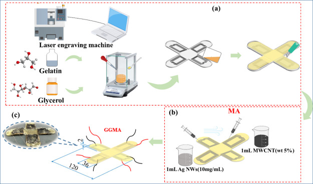
The sample preparation process for GG composite is shown in Figure 1a. First, the raw materials with the order of gelatin (1g) and glycerol (1.2 g) were weighed and placed in a small beaker. Afterward, the mixture was agitated with a glass rod for 10 min constantly. Later, the mixture was heated in an oven to volatilize ethanol and then cooled to room temperature. Finally, the new mixture was placed on a magnetic stirrer and mixed well. Then, it was put into a vacuum drying oven for 15 min to remove the air bubbles from the mixture under room temperature.
Figure 1.
Preparation process of GG/MA electric elastomer. (a) Schematic diagram of preparation of GG substrate. (b) Schematic diagram of injection process of MA conductive layer. (c) Schematic diagram of GG/MA electric elastomer (unit: mm).
In addition, polymeric methyl methacrylate (PMMA) boards (0.1 mm of the thickness) were engraved by a laser engraving machine to form the mold of the spider foot with the microchannels, which will form the conductivity wires by the engraving machine as shown in Figure 1a. Then, the mixture of gelatin and glycerol was slowly poured into the mold, except for the microchannels. Then, we placed the whole mold in an oven for 30 min at 70 °C and performed demolding to obtain the spider-inspired soft robot as shown in Figure 1a. Note that it is important to ensure that the gelatin is cured completely.
We took a 1:1 solution (MA) of 5 g of MWCNTs (wt 5%) and Ag NWs (10 mg/mL) with a dropper, poured them into a small beaker, and stirred them with a glass rod until they are evenly mixed. Then, the mixture of MWCNTs and Ag NWs is slowly injected into the wire microchannels on the spider-inspired soft robot and heated in order to evaporate the solvent. We repeated the above injecting and heating operations, so that the conductive layer for fulfill the electromagnetic driving was obtained as shown in Figure 1b.
The copper wire stripping pliers were used to strip the insulation layers at both ends of the wires, and we used conductive glue to bond the wires at both ends of the conductive layer of the channel during the GG and MA molding process, respectively. In addition, the gelatin particles were heated, melted, and dipped with a spoon and coated on the conductive layer to encapsulate the conductive layer channel and finally we obtained the GG/MA electric elastomer as shown in Figure 1c.
Result and Discussion
3.1. Physical Property Analysis of the GG/MA Electric Elastomer
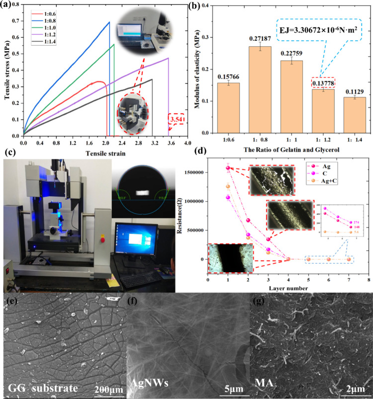
To determine the optimum mixing ratio of gelatin and glycerol, which act as the substrates of the spider-inspired soft robot, an investigation was conducted. The physical properties were thoroughly analyzed for different mixing ratios (1:0.6, 1:0.8, 1:1, 1:1.2, and 1:1.4) to provide a detailed understanding. As shown in Figure 2a, when the mixing ratio between gelatin and glycerol is 1:1.2, the composite film achieves a maximum strain of 3.54 as measured by the texture analyzer. By processing the stress–strain curve data, we can obtain the elastic modulus of the composite films with different proportions.
Figure 2.
Physical properties of GG substrates with different mixing ratios. (a) Stress–strain relationship of the GG composite film obtained by a texture analyzer. (b) Elastic modulus of the GG composite films with different proportions. (c) Hydrophobicity performance test and analysis. (d) Analysis of the conductive medium layers number. (e–g) SEM images with and without conductive medium. (n = 3, mean ± SD).
Analyzing the elastic modulus is of great significance to determine the best mixing ratio, which shows the ability of materials to resist deformation under stress and also reflects the deformation degree of materials under stress. The elastic modulus of the prepared GG composite film was found to range from 0.1129 to 0.27187 MPa as shown in Figure 2b. When compared with the known elastic modulus of PDMS (1–10 MPa) and rubber material (7.84 MPa),40,41 the GG substrate exhibited significantly lower elastic modulus values. An increase in the glycerol content corresponds to a decrease in elastic modulus, resulting in a softer substrate composite film. However, if the glycerol content is too high, such as the ratio of 1:1.4 between gelatin and glycerol, it is hard to move out from the mold because of the higher viscosity along with the increasing glycerol content. On the contrary, a decrease in glycerol content makes demolding during fabrication easier. However, if the content of the glycerol is too low, the elastomer cannot undergo molding. Therefore, the elastic modulus with the ratio of 1:0.6 between gelatin and glycerol is smaller than others as shown in Figure 2b.
Combining the elastic modulus of the material with the second moment of area of the section, the bending stiffness (EJ) can be calculated from Formula 1,
| 1 |
where EJ represents the bending stiffness, E represents the elastic modulus, and J represents the second moment of the area of the section.
Among them, the cross section of the elastomer can be regarded as a rectangle, so the second moment of area of the section can be calculated from Formula 2,
| 2 |
where b is the width of the elastomer (b = 36 mm) and h is the thickness of the elastomer (h = 2 mm).42 These sectional sizes of the soft robot feet are the same in the whole manuscript.
Bending stiffness is an important indicator for spider-inspired soft robots, representing the resistance of the material to bending under varying forces. A smaller bending stiffness results in a higher strain when the material is bent, reducing the bending resistance. Conversely, a greater bending stiffness makes it more challenging for the material to bend, indicating a higher stiffness. As shown in Figure 2b, because actuators made in different proportions have the same shape, it is easy to know a minimum bending stiffness (3.30672 × 10⁻⁶ N·m2), which is calculated when the mixing ratio between gelatin and glycerol is 1:1.2, excluding the ratio of 1:1.4 between gelatin and glycerol because of the difficult fabrication.
Therefore, the gelatin-glycerin composite film with a ratio of 1:1.2 exhibits easy demolding, low elastic modulus, and increased deformation under the same force, facilitating bending and movement. The 1:1.2 ratio of gelatin to glycerol was determined as the optimal mixing ratio for the electric elastomer substrate, serving as the substrate for the spider-inspired soft robot.
To assess the wettability of the GG/MA surface and explore its potential applications, a contact angle tester will be used, which will reflect the hydrophobicity or hydrophilic performance of the elastomer by measuring the shape of the droplet on the elastomer surface through image processing or measurement methods. If the droplet forms a large contact angle (greater than 90°) on the material surface, it indicates that the solid has good hydrophobicity. As shown in Figure 2c,43 the contact angle of 113.5° further proved its hydrophobicity, indicating favorable performance for subsequent humidity usage and demonstrating its environmental adaptability.
The performance of the conductive layer plays a crucial role in the bending performance of the elastomer. It not only ensures the stability of conductivity but also guarantees the reliability, durability, and uninterrupted conductive function of the elastomer during bending. We compared the relationship between the layer numbers and the resistance in three kinds of conductive media: Ag NWs, MWCNTs, and the mixture of MWCNTs and Ag NWs (MA) by a 1:1 mixing ratio as shown in Figure 2d. The minimum resistance of 5.6 Ω was achieved when using the mixture of MA as the conductive media. This can be attributed to the Ag NWs’ ability to maintain stable conductivity even under bending and stretching deformations, compensating for the susceptibility of MWCNTs to cracking and reduced conductivity. MWCNTs can compensate for the uneven distribution of Ag NWs wires caused by bubbles. Therefore, the 1:1 mixture of MWCNTs and Ag NWs is considered the optimal conductive medium, and it was chosen as the electromagnetic driving medium.
The scanning electron microscope (SEM) image of the GG substrate, Ag NWs, and MA mixture are shown in Figure 2e,f,g, respectively. It can be seen that there are some cracks on the surface GG substrate without electrical conductivity. Uneven distribution of Ag NWs was observed in certain areas on the surface of GG, which can adversely impact the conductivity due to the occurrence of aggregation. Meanwhile in the mixture MA, Ag NWs are covered with MWCNTs to improve the uneven distribution of pure Ag NWs, as shown in Figure 2g. The interface effect will occur on the contact interface between MWCNTs and Ag NWs with uniform dispersion, which will promote charge transfer and electron transport and enhance electrical conductivity.
3.2. Electromagnetic Property Analysis of the GG/MA Electric Elastomer
3.2.1. Reliability Analysis of GG/MA Actuators
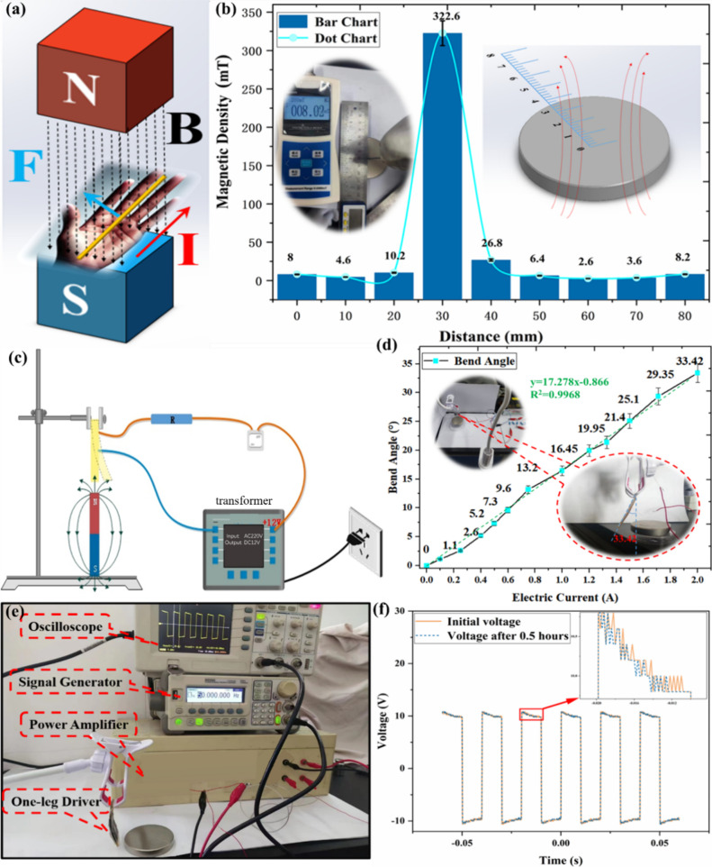
The GG/MA electro-elastomer uses Lorentz force to make bending motion, that is, when the conductor carries a current through a magnetic field, it will be subjected to a force perpendicular to the current direction and the magnetic field direction, as shown in Figure 3a. The force can be calculated by eq 3(44)
| 3 |
where F represents the magnetic field force acting on a wire (N), B represents the magnetic induction intensity in Tesla (t), I represents current (A) and L represents the length of the conductor (m).
Figure 3.
Electromagnetic performance analysis of the GG/MA elastomer. (a) Lorentz magnetic force principle diagram. (b) Distribution of magnetic field intensity at different positions of the magnet. (c) Bending angle measurement platform. (d) Relationship between the current and bending angle. (e) Fatigue test platform of the GG/MA electric elastomer. (f) Voltage changes before and after fatigue test (n = 5, mean ± SD).
Lorentz force is dependent on current, conductor length, and magnetic field intensity. In the case of the GG/MA electric elastomer, its deformation is primarily governed by the magnetic field and current. When a DC current is applied and interacts with a magnetic field, the left-hand rule dictates that a force perpendicular to both the current and magnetic field directions will be generated. This force causes the elastomer to bend in a specific direction, as depicted in Figure 3a. In order to obtain the bending performance of GG/MA as the foot of a spider-inspired soft robot, the influence of magnetic density and current should be analyzed.
Additionally, it is important to note that the magnetic induction intensity varies at different locations surrounding the circular magnet with a diameter of 60 mm, which was used as the driver. To determine the maximum magnetic density of the circular magnet, magnetometers were positioned at various points along the diameter, and the corresponding data were recorded, as shown in Figure 3b. A maximum magnetic field intensity of 322.6 mT was discovered at the edge of the magnet.
To facilitate the bending of the GG/MA electric elastomer, a magnetic driving platform was designed. The platform consists of a fixing bracket, a transformer for supplying power, a divider resistor, and a ring magnet for supplying magnetic field as shown in Figure 3c. When the current was applied to the GG/MA elastomer, it was affected by the magnetic field, resulting in the production of Lorentz force and bending, causing the material to deform. The relationship between bend angle and current applied on the GG/MA substrates were measured individually, and the results are shown in Figure 3d. The result revealed that the bending angle of the GG/MA elastomer basically increased linearly with the increase of the current, with a high correlation fitting coefficient (R2) of 0.9968. When the current was 0.5 A, a small bending angle of 5.2° was obtained by an angle measuring instrument. The current adjustment was controlled by the resistor string and parallel as shown in Figure 3d. The maximum bending angle of 33.42° was obtained when the current was 2.0 A.
The GG/MA electric elastomer will undergo repeated tensile and compressive deformation during practical usage, which will lead to fatigue damage inside the material and eventually to motion failure of the elastic body. Therefore, it is very important to evaluate the durability and life prediction of elastomer materials by simulating cyclic loading under actual working conditions. The fatigue test platform is shown in Figure 3e, where the signal generator produced a square wave with a frequency of 50 Hz and voltage of 10 V. This signal source was utilized to drive the GG/MA electric elastomer during the fatigue testing. An amplifier was used to amplify the voltage signal from the signal generator, and an oscilloscope was applied to display the real-time voltage changes under repeated bending of GG/MA. The voltages applied to the GG/MA before the fatigue test (initial voltage) and after subjecting it to repeated bending back and forth for 0.5 h are shown in Figure 3 (f). By comparing the two waveforms, it was found that the output voltage after bending 4500 times at both ends of the GG/MA films had no obvious drop. This represents that the resistance of the GG/MA electric elastomer maintains a stable value. Therefore, it can be shown that the electric elastic driver has a good fatigue resistance and long service life.
3.2.2. Stability Analysis of GG/MA Actuators
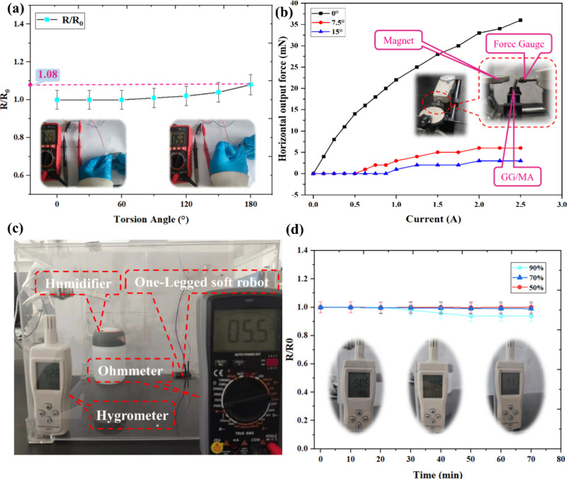
Exploring the torsional stability of the GG/MA electric elastic actuator allows for a deep understanding of its reliability and stability, providing a reliable guarantee for practical application and usage in spider-inspired soft robots. The change rate of the resistance along with the torsion angle was observed for GG/MA actuators during twist as shown in Figure 4a. It was found that the resistance exhibited a minimal variation. Even when the film was twisted by 180°, the R/R0 value was only 1.08, indicating excellent torsional stability of the actuators. This means that the driver can maintain relative stability in its resistance value during torsion with minimal changes resulting from twisting. These findings provide valuable experimental data for research and application in soft robot fields.
Figure 4.
Stability characteristic analysis of GG/MA electric elastomer. (a) Twist measurement, (b) relationship between current and output force, (c) physical diagram of humidity test experimental platform, and (d) experimental data of resistance change rate under different humidities (n = 5, mean ± SD).
In order to evaluate the output force and output control stability of GG/MA actuators, the horizontal output force test platform was designed as shown in Figure 4b. A magnet was fixed near the actuator and a digital force gauge was horizontally positioned as a force sensor. When the GG/MA actuator was powered on, the output force was measured by the force sensor. The horizontal output force of the GG/MA actuator was measured and increased along with the increase of current when the bending angle was 0°, 7.5°, and 15°. The results show that with the increase of deformation, the horizontal output force of the GG/MA actuator decreased significantly.
In order to explore the influence of humidity on the resistance performance of the GG/MA actuator, a humidity testing platform including humidifier, GG/MA actuator, humidity meter, and multimeter was designed here with a PMMA board as shown in Figure 4c. The different humidities, such as 50%, 70%, and 90%, were controlled by the humidifier and hygrometer. The resistance change of the GG/MA composites were measured under different humidities as shown in Figure 4d. The humidity was found to have little effect on the resistance change rate of the GG/MA electric elastomer under the 50% and 90% humidity. In the 90% humidity condition, the resistance change exhibited a slight decrease over time. This can be attributed to the hydrophilicity of glycerol and gelatin, which allows them to absorb water molecules in highly moist environments. The absorption of water molecules into the thin film increases the energy and conductivity of electron jumping, resulting in a reduction in the resistance value.
3.3. Motion Control Platform of the GG/MA Soft Robot
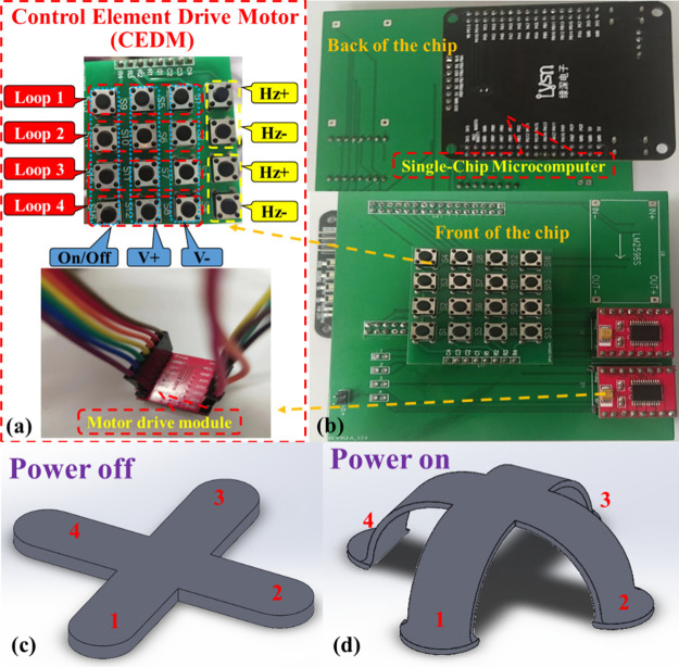
The control action analysis of the soft robot, a simulated spider, is of great significance to the soft robot’s movement. By controlling the power on and off of the four legs using the homemade control model detailed, respectively, an imitation spider soft robot can arch and move forward and backward.
The four legs of the spider soft robot adopt the principle of independent control, where each leg can be powered on and off independently, as shown in Figure 5a,b. When the corresponding switch is pressed, the corresponding leg will be powered on, and the frequency of power on and off can be adjusted by the frequency adjustment button. For example, if loop 1 was power on, leg 1 will bend and stretch, and the soft robot will move slowly. When the four switches are all pressed, the legs 1, 2, 3, and 4 of the spider-inspired soft robot will be powered on and arched downward, which can support a certain weight as shown in Figure 5c,d. Moreover, in the power-on state, adjusting the frequencies (current) of legs 2 and 4 enables the robot to move forward, while adjusting the frequencies of legs 1 and 3 allows for left and right movement. The detailed movement sequence of the spider-inspired soft robot is shown in Table 1.
Figure 5.
Motion control mechanism of GG/MA. (a) Switch, voltage, and frequency motion control module. (b) Four-leg integrated control module. (c) Status of the spider-inspired soft robot by GG/MA when powered off. (d) Status of the spider-inspired soft robot by GG/MA when powered on.
Table 1. Motion Sequence and Power Control Mode.
| loop 1 (frequency, on/off) | loop 2 (frequency, on/off) | loop 3 (frequency, on/off) | loop 4 (frequency, on/off) | state |
|---|---|---|---|---|
| off | off | off | off | static |
| 0.5 Hz on | on | 0.5 Hz on | on | slow move |
| 1 Hz on | on | 1 Hz on | on | fast move |
| 1.5 Hz on | on | 1.5 Hz on | on | vibration |
| 1 Hz on | 1 Hz on | 1 Hz on | 1 Hz on | hunch-up |
3.4. Inchworm-like Soft Robot’s Movement Performance Analysis with Two Legs
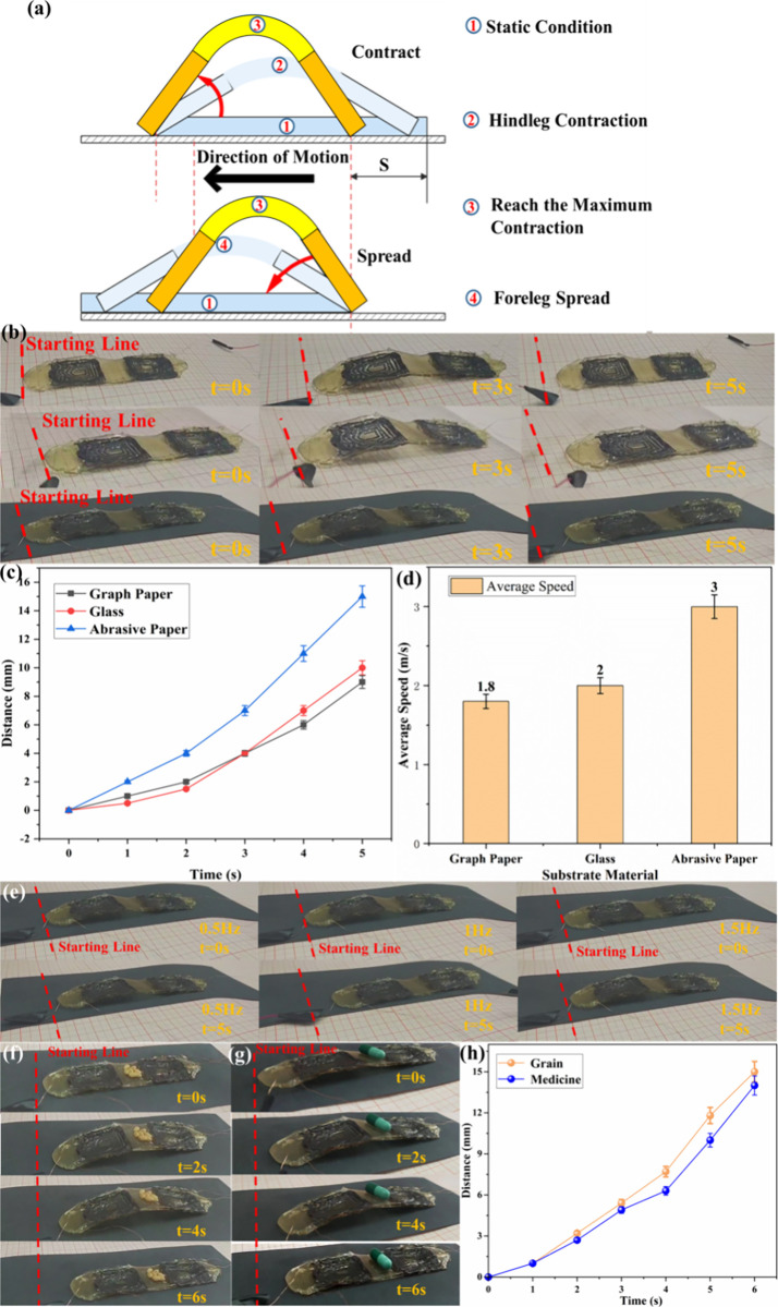
We can first consider the four legs of the spider-inspired robot as two inchworm-like robots that cross and cooperate to better illustrate their motion mode and characteristics. In order to analyze the movement gait more intuitively, we take a soft robot with two legs as an example. Figure 6a shows the movement mechanism of inchworm-inspired soft robot. There are five processes for the inchworm-like robot to complete a forward movement. They are stationary, their hind legs move forward and contract, and their front legs move forward and stand still. The leg of the robot is in a static state, and then the leg is in a second contraction state under the action of electromagnetic force. The direction of the current changes when it contracts to the apex shown in the third stage, and then the front legs extend and slide forward, as shown in the fourth stage. Until it reaches the fully extended state, that is, the short-term static state, the whole forward movement process is completed.
Figure 6.
Motion analysis of inchworm-inspired soft robot with the GG/MA electric elastomer by electromagnetic driving. (a) Movement giant analysis for the inchworm-inspired soft robot. (b) Real-time movement analysis for the inchworm-inspired soft robot on different bases (c) Distance–time curve of soft robot in different bases. (d) Average velocity of the inchworm-inspired soft robot with different substrates. (e) Motion state of soft robot at different frequencies. (f, g) Goods transportation performance by the soft robot. (h) Distance of soft robot on capsule and grains transportation at different instances (n = 5, mean ± SD).
During movement measurement, the robot was placed on the platform along with a circular magnet placed directly below the platform. In order to ensure the external magnetic field direction applied on the robot is always vertical and upward, the magnet should be maintained always below the robot manually. It is worth noting that the direction changing of the magnet field is little along with the robot foot bending, so it can be neglected during the below movement analysis.
3.4.1. Motion Velocity Analysis with Different Substrates
The motion speed of the inchworm-inspired soft robot is influenced by many factors, with one of the most significant being the substrates of the robot. As there are different motion characteristics and performances exhibited by various substrates, the motion speed of the inchworm-inspired soft robot also varies. This variability allows us to optimize the robot’s structure, enhance its motion performance and efficiency, and provide valuable insights and guidance for robot design and application.
Hence, experiments were conducted to determine the real-time movement speed of the inchworm-inspired soft robot on different substrates, such as paper, glass, and sandpaper. The robot was driven by a voltage of 6.45 V and 1 Hz as shown in Figure 6b. The distance that the soft robot moves along with time under three different substrates was recorded as shown in Figure 6c,d. It was observed that the slopes of the three curves were initially small during the starting phase of movement. However, as time progressed, the slopes gradually increased, indicating an acceleration in speed. In other words, the movement speed was relatively low at the beginning, but significantly increased after approximately 2 s. The initial low movement speed may be attributed to the relatively weak grip of the soft robot’s legs during the starting phase, leading to some slippage in the original position. However, as the robot repeatedly bent its legs, the slippage gradually diminished, resulting in a noticeable improvement in the movement speed. It was observed that the soft robot achieved the greatest movement distance when operating on sandpaper as the substrate. This can be attributed to the fact that when the robot moved on graph paper, there was insufficient friction, leading to noticeable slippage, as shown in Figure 6a. When the substrate is glass, the GG/MA electric elastic actuator exhibits a certain level of viscosity, which hinders the forward movement of the soft robot. When the substrate is made of sandpaper, it can not only provide good friction but also have little viscous resistance with the electric elastic device. As a result, the soft robot achieves the greatest distance when moving on this substrate compared to the others. The average moving speed of soft robot under three different substrates was calculated and shown in Figure 6d: 1.8 mm/s on graph paper, 2 mm/s on glass, and 3 mm/s on sandpaper. Consequently, the soft robot moves fastest on coarse surfaces such as sandpaper.
3.4.2. Motion Velocity Analysis with Different Frequencies
The driving frequency has an important influence on the performance and behavior of the soft robot. Varying the driving frequencies while maintaining a fixed driving voltage can result in different deformation, motion, and control characteristics.
In this experiment, a dual-channel signal generator was used to generate rectangular square wave signals with frequencies of 0.5, 1, and 1.5 Hz, which were used to drive the motion of the inchworm-inspired soft robot as shown in Figure 6e. The optimal frequency was determined by observing the motion of the soft robot at these three frequencies. The experimental results show that when the driving frequency was 0.5 Hz, the soft robot moved forward by 5 mm in 5 s, and the deformation and movement speed of the soft robot was slow. When the driving voltage frequency was 1 Hz, the soft robot moved forward by 15 mm in 5 s, and the deformation and movement speed of the soft robot was faster. Upon testing with a driving voltage of 1.5 Hz, it was observed that the soft robot exhibited a limited response to the external control signal of this frequency and struggled to move forward effectively. Consequently, it can be concluded that 1 Hz is the most suitable driving frequency for the inchworm-inspired soft robot.
3.4.3. Load Analysis of Inchworm-Inspired Soft Robot Based on the GG/MA Electric Elastomer
In this experiment, seven wheat grains with a total weight of 0.375 g and one capsule with the total weight 0.471 g were considered as the loadings, and the driving voltage was set at 6.45 V and the frequency was 1 Hz, and the real-time movement of the inchworm-inspired soft robot was observed as shown in Figure 6f,g. Figure 6h shows the average moving speed with different loadings of 2.5 and 2.3 mm/s. During the startup stage, the motion speed of the soft robot was initially slow, resulting in a small slope of the curve. However, as time progressed, the motion speed gradually increased, leading to an increasing slope of the curve. Because of its small size, lightweight, and high flexibility, the soft robot can adapt to different working environments and terrains, so it can be used in a wider range of scenes. At the same time, based on the flexible movement of the inchworm-inspired soft robot, it can carry out more detailed handling operations, such as shuttling in a narrow space and marching in complex terrain. In addition, the inchworm-inspired soft robot can not only improve production efficiency but also transport goods without interference from external factors, which ensures safety and effectiveness and brings more convenience and benefits to automatic transportation, public safety, personal assistants, and so on.
3.5. Spider-Inspired Soft Robot Movement Analysis with Four Legs
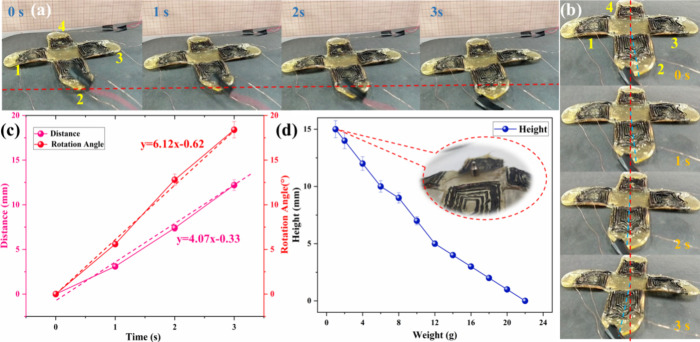
In order to simulate the spider motion, the soft robot with four legs was designed and fabricated. Additionally, four legs were included to provide support and prevent the soft robot from rolling over during the movement as shown in Figure 7a. The soft robot may walk in a straight line, resembling a spider, by electrifying legs 2 and 4 to provide a supportive force and reduce friction. Alternatively, directional movement can be achieved by alternately electrifying legs 1 and 3. The real-time schematic diagram is shown in Figure 7b. Figure 7c shows that the soft robot of the spider-inspired moved forward by 12.2 mm in 3 s, with an average moving speed of 4.07 mm/s. Compared with the inchworm-like soft robot, the average movement speed has increased. The reason is that the extra two legs increase their own weight and friction, but during the movement, it is found that the movement stability of the spider-like soft robot has improved obviously. Additionally, when legs 1 and 3 are energized at the same time, when the frequency of leg 1 is 1 Hz and the frequency of leg 2 is 1.5 Hz, the soft robot will rotate, with an average degree of 6.12°/s, which expands the selectivity of its motion direction and broadens its application field. Comparing with the jellyfish inspired soft robot mentioned in ref (15), the spider-inspired robot proposed in this research has a smaller volume, moving easily under different situations.
Figure 7.
Spider-inspired soft robot’s movement analysis. (a) Real-time movement forward, (b) real-time movement rotation, (c) distance–time and rotation–time curves of the spider-inspired soft robot, and (d) loading performance analysis of spider-inspired soft robot (n = 5, mean ± SD).
Moreover, utilizing a standard weight as the supporting object allows for a gradual increase of the test load. By incremental addition of weight, the height supported by the robot was recorded after each increment until the robot reached its maximum load-bearing capacity. Figure 7d shows that the soft robot was capable of supporting a weight of 1 g at a height of 15 mm. With the increase of the weight on spider inspired robot, the supporting height of the robot gradually decreased. Until the maximum weight of 22 g was reached, the robot could no longer support it, and the maximum carrying capacity exceeded its own weight, which means that the soft robot has a certain bearing capacity and can bear loads beyond its own weight without being damaged. In conclusion, the spider-inspired soft robot not only moves faster than the inchworm-inspired soft robot but also can bear heavier objects.
4. Conclusions
To address the challenge posed by traditional rigid materials, which typically possess a high elastic modulus and limited flexibility, a cross-shaped GG/MA elastomer matrix was designed and manufactured. This elastomer matrix featured a low elastic modulus and was manufactured by using a gelatin and glycerol mass ratio of 1:1.2. During the stress–strain experiment, data analysis revealed that the GG/MA elastomer exhibited an elastic modulus of 1.17 MPa, demonstrating a high degree of deformation and flexibility. The conductive properties of the elastomer mixed with Ag NWs and multiwalled carbon nanotubes were studied, and the best conductive medium of 7 layers was determined. The lateral output force, fatigue test, and torsion experiment of GG/MA elastomer prove that the elastomer has large output force, torsional stability, and high reliability. The motion characteristics of the GG/MA elastomer soft robot in different base materials, different driving voltage frequencies, and transporting and lifting heavy objects were studied, and the optimal driving voltage (6.45 V) frequency (1 Hz) was determined. In the case of supporting 0.375 and 0.471 g of goods, the average moving speed is 2.5 and 2.3 mm/s, respectively, which proves that the soft robot has goods transportation capacity. Furthermore, the spider-inspired soft robot exhibited an actuating velocity of 4.07 mm/s, indicating excellent magnetic control sensitivity and stability. Finally, a cargo analysis was conducted on the imitation starfish soft robot, revealing a maximum carrying capacity of 22 g. This finding highlights the robot’s commendable load-bearing capability. However, the wireless Bluetooth module will be equipped on the control circuit, which will make the robot movement more smooth and easier. In addition, the strong external magnetic field will be introduced to drive the soft robot in future research.
Acknowledgments
The authors expressed their gratitude to the Fund of Henan Key Laboratory of Superhard Abrasives and Grinding Equipment, Henan University of Technology (Grant No: JDKFJJ2023013). The research is also supported by the Zhengzhou Collaborative Innovation Project (22ZZRDZX18), the Henan Province High end Foreign Expert Project (HNGD2023020) and the Henan Province Foreign Expert Working Studio Project (GZS2024012). Moreover, it is supported by the Henan Province scholarship program for Overseas Students.
Author Contributions
Y.F.G. designed and directed the study. L.Y. performed the experiments and analyzed data. Y.F.G. and L.Y. wrote the paper. Y.F.G. reviewed and edited the manuscript. Y.S.L., W.Y., and Q.Y.Z. performed some experiments in the application part of the manuscript. Y.L.K., L.Z., S.L.Z., K.E., and H.Y.C. contributed to put forward valuable opinions on the perfection of the thesis. Z.C.L., Y.H.J., and Z.Y.X. analyzed and verified the experimental results. This manuscript was written with the contributions of all authors. All authors approved the final version of the manuscript.
The authors declare no competing financial interest.
References
- Lee C.; Kim M.; Kim Y. J.; Hong N.; Ryu S.; Kim H. J.; Kim S. Soft robot review. International Journal of Control Automation & Systems 2017, 15 (1), 3–15. 10.1007/s12555-016-0462-3. [DOI] [Google Scholar]
- Park Y.; Jung J.; Lee Y.; Lee D.; Vlassak J. J.; Park Y.-L. Liquid-metal micro-networks with strain-induced conductivity for soft electronics and robotic skin. npj Flexible Electronics 2022, 6 (1), 81. 10.1038/s41528-022-00215-2. [DOI] [Google Scholar]
- Zhao R.; Dai H.; Yao H. Liquid-Metal Magnetic Soft Robot With Reprogrammable Magnetization and Stiffness. IEEE Rob. Autom. Lett. 2022, 7 (2), 4535–4541. 10.1109/LRA.2022.3151164. [DOI] [Google Scholar]
- Proietti T.; O’Neill C.; Hohimer C. J.; Nuckols K.; Clarke M. E.; Zhou Y. M.; Lin D. J.; Walsh C. J. Sensing and Control of a Multi-Joint Soft Wearable Robot for Upper-Limb Assistance and Rehabilitation. IEEE Robotics and Automation Letters 2021, 6 (2), 2381–2388. 10.1109/LRA.2021.3061061. [DOI] [Google Scholar]
- Feng N.; Shi Q.; Hong W.; Gong J.; Lu Z. A soft robotic hand: design, analysis, sEMG control, and experiment. Int. J. Adv. Manuf. Technol. 2018, 97 (7553), 319. 10.1007/s00170-018-1949-2. [DOI] [Google Scholar]
- Koo S. H.; Lee Y. B.; Kim C.; Kim G.; Lee G.; Koh J.-S. Development of gait assistive clothing-typed soft wearable robot for elderly adults. International Journal of Clothing Science and Technology 2021, 33 (4), 513–541. 10.1108/IJCST-04-2020-0052. [DOI] [Google Scholar]
- Watson C.; Morimoto T. K. Permanent Magnet-Based Localization for Growing Robots in Medical Applications. IEEE Robotics and Automation Letters 2020, 5 (2), 2666–2673. 10.1109/LRA.2020.2972890. [DOI] [Google Scholar]
- Ribuan M. N.; Wakimoto S.; Suzumori K.; Kanda T. Omnidirectional Soft Robot Platform with Flexible Actuators for Medical Assistive Device. International Journal of Automation Technology 2016, 10 (4), 494–502. 10.20965/ijat.2016.p0494. [DOI] [Google Scholar]
- Huang T.-Y.; Qiu F.; Tung H.-W.; Chen X.-B.; Nelson B.J.; Sakar M.S. Generating mobile fluidic traps for selective three-dimensional transport of microobjects. Appl. Phys. Lett. 2014, 105 (11), 114102 10.1063/1.4895937. [DOI] [Google Scholar]
- Chen L.; Weng M.; Zhou Z.; Zhou Y.; Zhang L.; Li J.; Huang Z.; Zhang W.; Liu C.; Fan S. Large-Deformation Curling Actuators Based on Carbon Nanotube Composite: Advanced-Structure Design and Biomimetic Application. ACS Nano 2015, 9 (12), 12189–96. 10.1021/acsnano.5b05413. [DOI] [PubMed] [Google Scholar]
- Guo R.; Sheng L.; Gong H.; Liu J. Liquid metal spiral coil enabled soft electromagnetic actuator. Science China Technological Sciences 2018, 61 (4), 516–521. 10.1007/s11431-017-9063-2. [DOI] [Google Scholar]
- Tolley M. T.; Shepherd R. F.; Mosadegh B.; Galloway K. C.; Wehner M.; Karpelson M.; Wood R. J.; Whitesides G. M.; Resilient A. Untethered Soft Robot. Soft Rob. 2014, 1 (3), 213–223. 10.1089/soro.2014.0008. [DOI] [Google Scholar]
- Diller E.; Giltinan J.; Lum G. Z.; Ye Z.; Sitti M. Six-degree-of-freedom magnetic actuation for wireless microrobotics. International Journal of Robotics Research 2016, 35 (1–3), 114–128. 10.1177/0278364915583539. [DOI] [Google Scholar]
- Li J.; Zhang R.; Mou L.; Jung de Andrade M.; Hu X.; Yu K.; Sun J.; Jia T.; Dou Y.; Chen H. Photothermal bimorph actuators with in-built cooler for light mills, frequency switches, and soft robots. Adv. Funct. Mater. 2019, 29 (27), 1808995 10.1002/adfm.201808995. [DOI] [Google Scholar]
- Ramses J. L. B.; Martinez V.; Fish C. R.; Jin L.; Shepherd R. F.; Nunes R. M. D.; Suo Z.; Whitesides G. M. Robotic Tentacles with Three-Dimensional Mobility Based on Flexible Elastomers. Adv. Mater. 2013, 25 (2), 153–153. 10.1002/adma.201203002. [DOI] [PubMed] [Google Scholar]
- Lee J.G.; Rodrigue H., Origami-Based Vacuum Pneumatic Artificial Muscles with Large Contraction Ratios, Soft Robotics (2019). 6109. 10.1089/soro.2018.0063. [DOI] [PubMed] [Google Scholar]
- Oulmas A.; Andreff N.; Regnier S., 3D closed-loop motion control of swimmer with flexible flagella at low Reynolds numbers. 2017 IEEE/RSJ. International Conference on Intelligent Robots and Systems (IROS); IEEE; 2017.
- Wang C.; Puranam V. R.; Misra S.; Venkiteswaran V. K. A Snake-Inspired Multi-Segmented Magnetic Soft Robot Towards Medical Applications. IEEE Robotics and Automation Letters 2022, 7 (2), 5795–5802. 10.1109/LRA.2022.3160753. [DOI] [Google Scholar]
- Li T.; Li G.; Liang Y.; Cheng T.; Dai J. Fast-moving soft electronic fish. Sci. Adv. 2017, e1602045 10.1126/sciadv.1602045. [DOI] [PMC free article] [PubMed] [Google Scholar]
- Shintake J.; Rosset S.; Schubert B.; Floreano D.; Shea H. Versatile Soft Grippers with Intrinsic Electroadhesion Based on Multifunctional Polymer Actuators. Adv. Mater. 2016, 28 (2), 205–226. 10.1002/adma.201504264. [DOI] [PubMed] [Google Scholar]
- Arazoe H.; Miyajima D.; Akaike K.; Araoka F.; Sato E.; Hikima T.; Kawamoto M.; Aida T. An autonomous actuator driven by fluctuations in ambient humidity. Nat. Mater. 2016, 1084. 10.1038/nmat4693. [DOI] [PubMed] [Google Scholar]
- Ionov Leonid Hydrogel-based actuators: possibilities and limitations. Mater. Today 2014, 17 (10), 494–503. 10.1016/j.mattod.2014.07.002. [DOI] [Google Scholar]
- Yu Y.; Nakano M.; Ikeda T. Directed bending of a polymer film by light. Nature 2003, 145. 10.1038/425145a. [DOI] [PubMed] [Google Scholar]
- Taccola S.; Greco F.; Sinibaldi E.; Mondini A.; Mazzolai B.; Mattoli V. Toward a new generation of electrically controllable hygromorphic soft actuators. Adv. Mater. 2015, 27 (10), 1668–75. 10.1002/adma.201404772. [DOI] [PMC free article] [PubMed] [Google Scholar]
- Acome E.; Mitchell S. K.; Morrissey T. G.; Emmett M. B.; Benjamin C.; King M.; Radakovitz M.; Keplinger C. Hydraulically amplified self-healing electrostatic actuators with muscle-like performance. Science 2018, 359 (Jan.5 TN.6371), 61–65. 10.1126/science.aao6139. [DOI] [PubMed] [Google Scholar]
- Morin S. A.; Shepherd R. F.; Kwok S. W.; Stokes A. A.; Nemiroski A.; Whitesides G. M. Camouflage and display for soft machines. Science 2012, 337 (6096), 828–832. 10.1126/science.1222149. [DOI] [PubMed] [Google Scholar]
- Polygerinos P.; Wang Z.; Galloway K. C.; Wood R. J.; Walsh C. J. Soft robotic glove for combined assistance and at-home rehabilitation. Robotics Autonomous Systems 2015, 73, 135–143. 10.1016/j.robot.2014.08.014. [DOI] [Google Scholar]
- Hu W.; Lum G. Z.; Mastrangeli M.; Sitti M. Small-scale soft-bodied robot with multimodal locomotion. Nature 2018, 81. 10.1038/nature25443. [DOI] [PubMed] [Google Scholar]
- Kim Y.; Parada G. A.; Liu S.; Zhao X. Ferromagnetic soft continuum robots. Science Robotics 2019, 4 (33), eaax7329 10.1126/scirobotics.aax7329. [DOI] [PubMed] [Google Scholar]
- Xu T.; Zhang J.; Salehizadeh M.; Onaizah O.; Diller E. Millimeter-scale flexible robots with programmable three-dimensional magnetization and motions. Sci. Robot. 2019, 4 (29), eaav4494 10.1126/scirobotics.aav4494. [DOI] [PubMed] [Google Scholar]
- Jin S. W.; Park J.; Hong S. Y.; Park H.; Jeong Y. R.; Park J.; Lee S. S.; Ha J. S. Stretchable Loudspeaker using Liquid Metal Microchannel. Sci. Rep. 2015, 5, 11695. 10.1038/srep11695. [DOI] [PMC free article] [PubMed] [Google Scholar]
- Rui G.; Lei S.; Hengyi G.; Jing L. Liquid metal spiral coil enabled soft electromagnetic actuator. Sci. China Technol. Sci. 2018, 61 (04), 516. 10.1007/s11431-017-9063-2. [DOI] [Google Scholar]
- Mao G.; Drack M.; Karami-Mosammam M.; Wirthl D.; Stockinger T.; Schwödiauer R.; Kaltenbrunner M. Soft electromagnetic actuators. Science advances 2020, 6 (26), eabc0251 10.1126/sciadv.abc0251. [DOI] [PMC free article] [PubMed] [Google Scholar]
- Aksoy B.; Shea H. Multistable shape programming of variable-stiffness electromagnetic devices. Sci. Adv. 2022, 8 (21), eabk0543 10.1126/sciadv.abk0543. [DOI] [PMC free article] [PubMed] [Google Scholar]
- Zhao R.; Yao H.; Dai H. Shape Programmable Magnetic Pixel Soft Robot. Robotics 2021, e11415 10.48550/arXiv.2111.00422. [DOI] [PMC free article] [PubMed] [Google Scholar]
- Ma W. Q. Z.; Wu Z. Superconducting-Material-Based Maglev Generator Used for Outer-Space. Adv. Mater. 2022, 34 (33), 2203814 10.1002/adma.202203814. [DOI] [PubMed] [Google Scholar]
- Miao L.; Song Y.; Ren Z.; Xu C.; Wan J.; Wang H.; Guo H.; Xiang Z.; Han M.; Zhang H. 3D Temporary-Magnetized Soft Robotic Structures for Enhanced Energy Harvesting. Adv. Mater. 2021, 33, e2102691 10.1002/adma.202102691. [DOI] [PubMed] [Google Scholar]
- Alapan Y.; Yasa O.; Schauer O.; Giltinan J.; Tabak A.F.; Sourjik V.; Sitti M. Soft erythrocyte-based bacterial microswimmers for cargo delivery. Sci. Robot 2018, 3 (17), eaar4423 10.1126/scirobotics.aar4423. [DOI] [PubMed] [Google Scholar]
- Guan Y.; Liu Y.; Wang Q.; Geng H.; Cui T.; Hu Y.; Luo Q.; Li A.; Li W.; Lin Y. Inchworm-Inspired soft robot with magnetic driving based on PDMS, EGaIn and NdFeB (PEN) combination. Chem. Eng. J. 2023, 466, 142994 10.1016/j.cej.2023.142994. [DOI] [Google Scholar]
- Béfahy S.; Lipnik P.; Pardoen T.; Nascimento C.; Patris B.; Bertrand P.; Yunus S. Thickness and elastic modulus of plasma treated PDMS silica-like surface layer. Langmuir the Acs Journal of Surfaces 2010, 26 (5), 3372. 10.1021/la903154y. [DOI] [PubMed] [Google Scholar]
- Setiyana B.; Prabowo C.; Jamari J.; Ismail R.; Sugiyanto S.; Saputra E. Numerical investigation of the hardness of tire rubber material by indentation method. Journal of Physics: Conference Series 2020, 1517 (1), 012020 10.1088/1742-6596/1517/1/012020. [DOI] [Google Scholar]; (6pp)
- Goodno J.M.G.a.B.J.Mechanics of materials, 8Th ed., Cengage Learning; (2013), page 976–977. [Google Scholar]
- Wu Z.; Shi C.; Chen A.; Li Y.; Chen S.; Sun D.; Wang C.; Liu Z.; Wang Q.; Huang J. Large-Scale, Abrasion-Resistant, and Solvent-Free Superhydrophobic Objects Fabricated by a Selective Laser Sintering 3D Printing Strategy. Adv. Sci. 2023, 2207183 10.1002/advs.202207183. [DOI] [PMC free article] [PubMed] [Google Scholar]
- Tsubasa K.; Takaya I.; Koichi H. Analytical Lorentz Force Model Between 1-D Linear Currents in Arbitrary Relative Positions and Directions. IEEE Trans. Magn. 2018, PP (8), 1–16. 10.1109/TMAG.2018.2841382. [DOI] [Google Scholar]


