Abstract
Singularity in a two-point complex coherence function, known as coherence vortices, represents zero visibility with a helical phase structure. In this paper, we introduce a novel technique to generate the coherence vortices of different topological charges by incoherent source transmittance with exotic structured binary pinholes. The binary pinhole structures have been realized by lithography, followed by wet etching methods. We control the transmittance from the incoherent source plane using these exotic apertures, which finally results in a coherence vortex spectrum that features multiple and pure orbital angular momentum modes. The generation of the coherence vortices is achieved within the two-point complex spatial coherence function. The spatial coherence function exhibits the helical phase profile in its phase part, and its absolute part shows a doughnut-shaped structure. A theoretical basis is developed and validated with simulation, and experimental results. The coherence vortex spectra with OAM modes superposed with opposite topological charges, known as photonic gears, are also generated with the proposed theory.
Keywords: coherence vortices, topological charge, orbital angular momentum, spatial coherence
1. Introduction
Singular optics, an area of intense research interest, addresses a diverse range of effects that occur close to locations where certain parameters of the wave field become singular or undefined [1], [2], [3], [4], [5], [6], [7], [8]. Over the last few decades, researchers have described several different kinds of singularities in the optical domain, such as phase singularities [1], [2], [3], [4], [5], polarization singularities [6], [7], and Poynting vector singularities [8]. Among all, phase singularities have attracted significant attention because of their capacity to carry orbital angular momentum (OAM) [9] and their various useful applications, including free-space optical communication [10], particle trapping and manipulation [11], [12], quantum computing [13], super-resolution imaging [14], and many more.
The vortex beams (VBs) exhibit intensity null around the phase singularity and the phase is undefined [4]. These beams are characterized by a helical phase wavefront with azimuthal phase dependence in the form of exp(ilθ), where l is the topological charge (TC) and θ is the azimuthal phase over the transverse plane. The total phase change around the phase singularity is 2πl, and the TC l is associated with the OAM of the photon as lℏ, where ℏ denotes the Planck constant [15]. Over the past few decades, various methods for generating phase singularities have been introduced. These include spiral phase plates [16], computer-generated holograms [17], light mode converters [18], plasmonic metasurfaces [19], and so on. Recently, fully coherent light arrays designed in a spiral structure have been used to create an optical vortex with a pure or multiple OAM. The specifically designed spiral structure provides freedom to tailor OAM spectrum of the beam [20], [21], [22]. Also, numerous techniques have been devised to identify the TC of a VB. Shack–Hartmann wavefront sensors [23], diffraction techniques [24], [25], interferometry [26], scattering [27], diffraction by pinhole [28], and ptychography [29] are a few of them.
The aforementioned research is mainly limited to coherent beams. Nonetheless, a coherent beam will distort, scintillate, or drift when it passes through a turbulent medium like fog or heat movement. However, a low coherent or partially coherent beams (PCB) have advantages over fully coherent beams in mitigating turbulence-induced effects [30]. Additionally, PCBs with vortex exhibit even greater advantages compared to those without vortex, particularly in minimizing turbulence-induced scintillations, presenting significant potential benefits for free-space optical communication [31], [32]. The partially coherent vortex beam (PCVB) is also used in optical imaging domains to minimize speckle noise [33] and in trapping particles having varying refractive indices [34]. Moreover, certain PCVB shows some special properties while propagation, such as self-splitting, self-focusing, and self-reconstruction making it suitable for applications such as information encryption and decryption [35], [36]. As a PCVB propagates, the phase singularities corresponding to the central zero intensity diminish, while correlation singularities characterized by zero cross-spectral density (CSD) function and undefined phase arise. Therefore, for PCV beams, while the random fluctuations of the light fields obscure the phase singular points of the averaged intensity, the singularities survive in the two-point correlation as correlation singularities or coherence vortices (CVs) [37]. Gbur and colleagues were the first to theoretically predict the presence of CVs. CVs contain a helical phase structure within a two-point correlation function [38]. The existence of CVs as ring dislocations in the cross-correlation function was first realized by Palacios et al. [39]. Subsequently, Wang et al. showed the existence of CVs in their generic form, exhibiting characteristic helical phase profiles associated with complex spatial coherence function [40]. Additionally, the method is applied to establish the law of conservation and to examine the local properties of the phase singularities in the spatial coherence function [41]. Singh et al. proposed a method involving three uniform independent circular apertures at the source plane to generate a coherence vortex array [42]. Recently, Liu et al. showed an experimental generation of coherence vortex by utilizing partially coherent light arrays [43]. Therefore, owing to the numerous benefits and advantages of CVs, it is essential to generate and detect CVs.
The detection of CVs serves a crucial purpose in measuring the TC, which proves highly beneficial in applications such as information photonics, and optical communication [44], [45]. Over the past decade, different techniques have been devised for measuring TCs using a variety of correlation functions, including the double-correlation function [46], complex degree of coherence [47], and cross-spectral density [48]. Subsequent studies [47], [49] revealed a direct connection between the number of ring dislocations observed in the cross-correlation function and the magnitude of the TC associated with a PCVB [50]. Theoretical investigations [51], [52] have further elucidated the relationship between the CVs and the magnitude of the TC, as well as the radial mode index of the vortex beam [53]. A technique utilizing dual cylindrical lenses for simultaneously measuring the magnitude and sign of the TC was proposed [54]. The determination of the TC of CVs has advanced through recent developments in phase detection of PCVB [48], [55], [56]. Recently, a phase detection method is proposed to enable simultaneous determination of both the amplitude and sign of the TC [56].
However, the generation of CVs with arbitrary TC composition is still unexplored except for some limited studies with a fixed TC. The purpose of this paper is to fill this gap and demonstrate an experimental method to generate and analyze the CV spectrum with pure and multiple OAM modes. For this purpose, we have specifically fabricated binary pinhole masks using lithography. Apart from a synthesis of the CVs, we have also designed a highly stable interferometer to experimentally measure the two-dimensional complex coherence function and confirm the presence of the CVs in two-point spatial coherence function at different longitudinal distances from the source plane. With this approach, using a single setup, we can retrieve the characteristic doughnut structure and helical phase profile of CVs in amplitude and phase part of complex two-point spatial coherence function flow in the three-dimension, respectively. Also, employing the same setup we generate the photonic gears in the coherence, i.e., OAM modes superposition with opposite TCs ± l. We have developed a theoretical framework and validated it with simulations and experimental tests. Additionally, the compositions of the topological spectrum in the CVs are confirmed by projecting the recovered complex field over the helical modes, and results are presented. The idea presented here is not limited to optical regime and this kind of pinhole mask can be further investigated for matter waves, e.g., in the context of photon sieves and Vogel spiral arrays, enabling the creation of more intricate structures and a greater diversity of structured beams [57], [58], [59], [60].
2. Principle and methods
2.1. Generation of coherence vortex with varying modes
The CSD function describes the spatial correlations of the field. For a two-dimensional wide-sense stationary source, it is represented as
| (1) |
where,
and
represents the far-field realizations at spatial points
r
1 and
r
2, respectively, and ω is the frequency.  represents ensemble averaging.
Figure 1 shows a binary spiral aperture illuminated with an incoherent light, using the angular spectrum of plane waves, the complex field at a distance z from the aperture plane can be expressed as [61]
| (2) |
where , r is the transverse position vector at a longitudinal plane z, and denotes wave number, λ is the wavelength and is the amplitude of the field. We neglected the contributions of the evanescent waves for a beam-like field.
Figure 1:
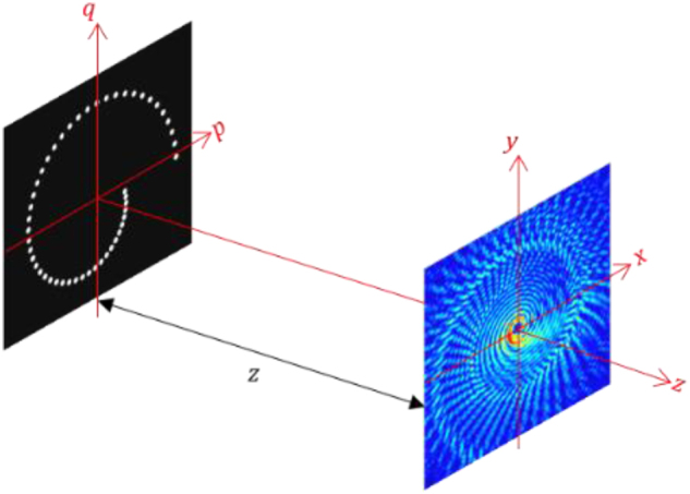
Schematic diagram for recording two-point spatial coherence function.
On substituting Eq. (2) into Eq. (1), we obtain
| (3) |
where , represents the angular correlation function of the field. If p 2 + q 2 ≪ k 2,
| (4) |
Therefore, Eq. (3) becomes
| (5) |
Considering and be the two-dimensional vectors at the transverse source plane. Thus, Eq. (5) reduces to
| (6) |
where for an incoherent source . Therefore, Eq. (6) becomes
| (7) |
where Δz = z 2 − z 1 and Δ r = r 2 − r 1. When Δz = 0, Eq. (7) reduces to the van Cittert–Zernike theorem which connects the two-point spatial coherence function with the incoherent source by the Fourier transform relation. Therefore, for Δz = 0,
| (8) |
where, is a real, non-negative weight function. Therefore, defining function with an appropriate spatial structure is sufficient to produce a specified far-field spatial coherence distribution. For a monochromatic light source, we have ignored ω from further consideration in the coming section.
Following beam shaping of the coherent light [21] and using the analogy between the optical field and complex coherence, we create an exotic incoherent source with structured transmittance . This is made up of several pinholes positioned at different spatial locations in the form of pinholes arranged in a spiral structure as shown in Figure 1. Experimental fabrication of the desired transmittance function for high-quality performance is discussed in the next section. The transmittance aperture is made up of the total N number of pinholes, the radius and azimuthal angle of nth pinhole from the center is set over the transverse plane such that
| (9) |
and
| (10) |
where, v 0 is the initial radius from the center to the first pinhole, l is the TC, λ is the wavelength and z is the distance from the pinhole mask to the observation plane.
To examine the generation of CVs, we implemented a two-pronged approach. First is the measurement of complex coherence. The presence of helical phase structure in order of multiple of 2π is used to test and confirm the CV in the beam. Second is an analysis based on examining the composition of the TCs spectrum in the beam. The orthogonal projection method is implemented to analyze the TCs spectrum in the low coherent beam. Here, the complex coherence function is projected onto spiral harmonics , where l represents the TC [62], [63]. To examine the TC power spectrum, we determine the complex coefficient A l by applying an angular Fourier transform of over azimuthal angle,
| (11) |
Every TC mode is associated with a complex coefficient A l , that varies with the radial coordinates. The TC mode power spectrum of the beam is then calculated using a numerical integration across the modulus square of A l for the radial coordinates,
| (12) |
where, represents the TCs power spectrum and is the beam power.
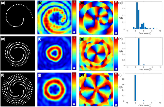
To examine the proposed method, we have simulated the incoherent source with binary pinholes and demonstrated generation of CVs in the beam. For simulation, we modeled the spiral pinhole aperture using Eqs. (9) and (10). The source plane is comprised of the pinhole aperture expressed as a two-dimensional matrix , with L × L elements, where a and b are pixels. An incoherent source is modeled using a set of random phase screens. These phase screens introduce random phase values uniformly distributed over the interval [–π, π]. Propagation of incoherent beam through the transmittance function is modeled using angular spectrum method and complex coherence is further propagated using Eq. (7). In simulation, we considered the initial radius from the center to the first pinhole to be r 0 = 1 mm, wavelength λ = 632.8 nm, total number of pinholes N = 50, Δz = 1 m. Figure 2 displays our simulated results.
Figure 2:
Schematics of the discretized binary spiral pinhole apertures. (a) Single spiral, (e) three spirals, and (i) five spirals; (b), (f), and (j) the corresponding simulated absolute values of complex spatial coherence function; (c), (g), and (k) the corresponding simulated phase values of complex spatial coherence function; (d), (h), and (l) the corresponding TC mode power spectrum.
Figure 2(a) shows the binary spiral pinhole aperture. Figure 2(b) and (c) display the amplitude and phase parts of the simulated complex spatial coherence function arising from incoherently illuminated spiral pinhole aperture as shown in Figure 2(a), respectively. Figure 2(d) presents the corresponding TC spectrum, illustrating the power spectrum of TC modes. The coherence vortex spectra can be tuned to a specific TC mode by adding identical copies of the spiral pinhole plates uniformly distributed along the azimuth as shown in Figure 2(e) and (i). Figure 2(e) shows three spiral pinhole structures evenly allocated along the azimuthal direction. Figure 2(f) and (g) show the corresponding amplitude and phase of spatial coherence function, respectively, and Figure 2(h) is the associated coherence vortex spectra with specific TC mode with TC l = −3. Similarly, Figure 2(i) shows five spiral pinhole structures uniformly placed along the azimuthal direction. Figure 2(j) and (k) show the corresponding amplitude and phase of spatial coherence function, respectively, and Figure 2(l) is the associated coherence vortex spectra with specific TC mode with TC l = −5. Here, an m-order rotationally symmetric structure can only select TC modes that are multiples of m, while discarding all other modes, and such features have been demonstrated for the fully coherent beam in Ref. [60], [64]. For this reason, particular TC values l = −3 and −5 are visible in the spectra displayed in Figure 2(h) and (l), respectively. If we consider the anti-clockwise rotation of spiral masks instead of clockwise rotation along the azimuth, it finally results in TCs with positive values.
2.2. Coherence vortex with ±l modes
We also create the superposition of two vortex beams with opposite TC: ± l, i.e., photonic gears in coherence function. To create a far-field coherence vortex spectrum with this feature, we have selected in such a way that two spiral pinhole masks with opposite TC values are combined. If the total number of pinholes azimuthally placed in clockwise and anticlockwise order are N and M, respectively. The radius and azimuthal angle of nth pinhole in the mth spiral are
| (13) |
and
| (14) |
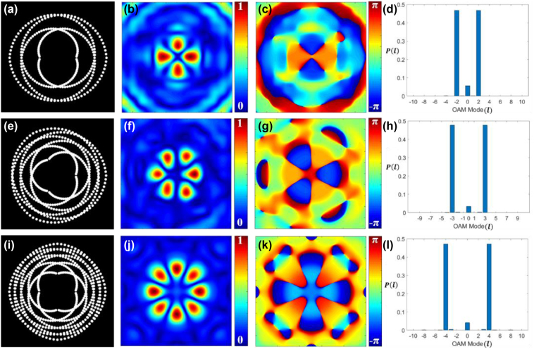
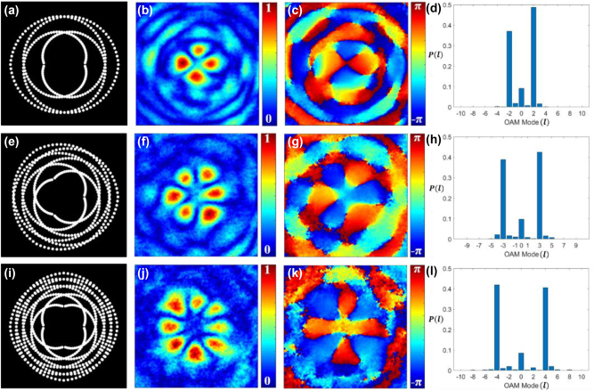
Following the simulation process described previously, we modeled the propagation of an incoherent beam from the pinhole gears, and the complex coherence results were evaluated at different distances from the aperture plane. Figure 3(a), (e), and (i) show the binary pinhole masks produced through simulation which generates the pinhole gears with superposition of modes l = ±2, l = ±3, and l = ±4, respectively. Figure 3(b), (f), and (j) represent the absolute part of the complex coherence function. The superposition of two vortex beams with opposite TCs ± l is known to produce an intensity pattern with 2l petal-like features in it [21]. The spatial coherence function also exhibits the same kind of 2l petal-like distribution as demonstrated in Figure 3(b), (f), and (j). Figure 3(c), (g), and (k) show the phase distribution of the complex spatial coherence corresponding to Figure 3(a), (e), and (i), respectively. It is demonstrated that the generated coherence vortex mode spectra exhibit highly pure helical modes, as shown in Figure 3(d), (h), and (l), corresponding to Figure 3(a), (e), and (i), respectively.
Figure 3:
Schematics of the pinhole gears. Binary pinhole masks for OAM modes with (a) l = ±2, (e) l = ±3, and (i) l = ±4; (b), (f), and (j) the corresponding simulated absolute values of complex spatial coherence function; (c), (g), and (k) the corresponding simulated phase values of complex spatial coherence function; (d), (h), and (l) the corresponding TC mode power spectrum.
3. Experiment and results
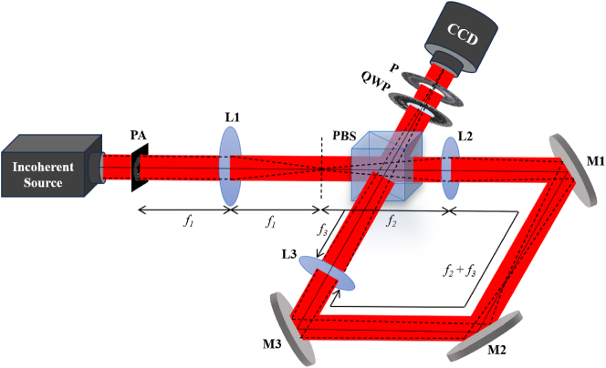
Following the description of our simulations, experimental tests were carried out to confirm and support our findings. Figure 4 shows our proposed experimental setup. A He–Ne laser of wavelength 632.8 nm illuminates a rotating ground glass disk (RGGD) to generate a spatially incoherent source. Immediately after the RGGD, we placed a binary pinhole aperture (6.5 mm aperture). The pinholes have a diameter of 150 μm. The binary pinhole structures have been realized by lithography, followed by wet etching methods. First, a positive photoresist (S1813 from Micro Resist Technology, Germany) was coated on a 100 nm thick chrome-coated glass substrate. Desired structures were fabricated on this substrate by lithography using a maskless lithography system (SF-100 from Intelligent Micropatterning USA). After development, the substrate was dipped in chrome etchant (Etch-18, from Micro Resist Technology, Germany) for the removal of chrome from exposed parts. Finally, the photoresist was removed and the substrate was cleaned to achieve the desired mask structures. The incoherent source, i.e. transparency is placed at the back focal plane of a bi-convex lens L1 of focal length f 1 = 10 cm, and the back focal plane of this lens is represented by a dotted line in Figure 4. We experimentally measured the complex coherence of the beam at the back focal plane. To measure the complex coherence function arising from the specially designed incoherent source at the far-field as indicated by the black dotted line in Figure 4, we have designed a Sagnac shearing interferometer composed of a polarization beam splitter (PBS), three mirrors M1, M2, and M3, and two lenses L2 and L3 of focal length f 2 = 17.5 cm and f 3 = 20 cm, respectively. The incoming beam is split into x and y polarized beams by the PBS. The interferometer is configured to ensure that the two counter-propagating beams undergo magnification and demagnification with magnification factors α = f 3/f 2 = 1.143 and α −1 = f 2/f 3 = 0.875, respectively. Consequently, at the output of the interferometer, we observe two sheared copies of the counter-propagating beams reaching the CCD plane. Thus, at any position in the detector, we have two scaled replicas of the fields with scaling r 1 = α −1 r and r 2 = α r . Before the detector, a quarter wave plate (QWP) and a polarizer (P) are placed to implement the four-phase shifting technique. The QWP changes the polarization states, converting the x-polarized beams to right circular polarization and the y-polarized beams to left circular polarization. Later, polarizer will give the required phase shift and help the two orthogonal beams to interfere [65]. Therefore, at the detector plane, the average intensity is determined as
| (15) |
where is the total average intensity and , and are average intensities at points r 1 and r 2. is the fringe visibility and is the corresponding phase due to the two interfering beams, and 2θ is the constant phase resulting from the polarization rotation. Therefore, a phase shift of 2θ is introduced between the two interfering beams by rotating polarizer P by an angle θ.
Figure 4:
Experimental setup: PA, binary pinhole aperture; L, lens; PBS, polarization beam splitter; M, mirror; QWP, quarter wave plate; P, polarizer; CCD, charge-coupled device.
Therefore, four interference patterns , , and are recorded with phase-shifts 0, π/2, π, and 3π/2, respectively. Using the four-phase shifting algorithm, the fringe visibility and corresponding phase will be determined from these interference patterns, as described by
| (16) |
and
| (17) |
Using Eqs. (16) and (17) the complex spatial coherence function is reconstructed as
| (18) |
Figure 5 represents four experimentally recorded interference patterns , , and with phase-shifts 0, π/2, π, and 3π/2, respectively, at the CCD plane for single spiral pinhole aperture. These interference patterns were processed and converted into grayscale image using MATLAB for visual enhancement. Later, the complex spatial coherence function is digitally reconstructed using Eqs. (16)–(18). Similarly, the interference patterns corresponding to different spiral pinhole apertures placed after RGGD are recorded, and the results for reconstructed complex spatial coherence function and corresponding coherence vortex spectrum are presented in Figure 6.
Figure 5:
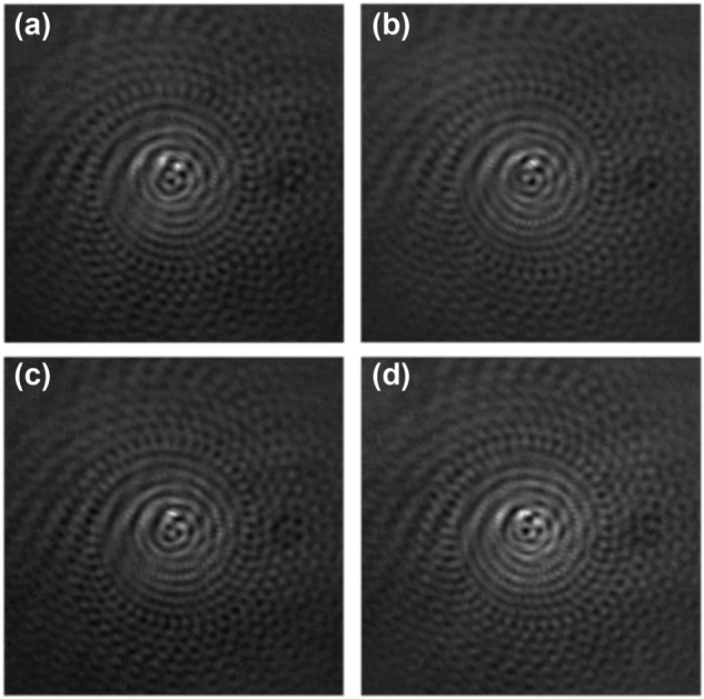
Recorded interference patterns for a single spiral with phase-shifts (a) 0, (b) π/2, (c) π, and (d) 3π/2.
Figure 6:
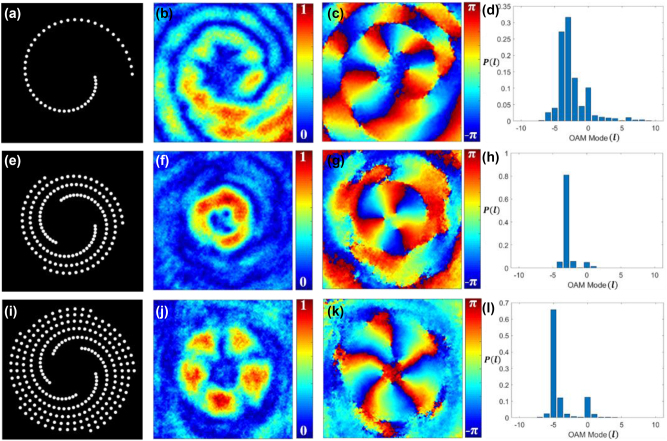
Experimental results. (a) Single spiral, (e) three spirals, and (i) five spirals; (b), (f), and (j) the corresponding absolute values of the complex spatial coherence function; (c), (g), and (k) the corresponding phase values of the complex spatial coherence function; (d), (h), and (l) the corresponding TC mode power spectrum.
Figure 6 represents our experimental results corresponding to simulation results presented in Figure 2. Figure 6(a), (e), and (i) display the binary spiral pinhole apertures with a single spiral, three spirals, and five spirals, respectively. Figure 6(b), (f), and (j) represent the experimental results for the corresponding absolute value of complex spatial coherence and Figure 6(c), (g), and (k) are the corresponding phase values of complex spatial coherence. Figure 6(d), (h), and (l) present the corresponding coherence vortex spectrum, illustrating the power weight distribution of helical modes. Therefore, the experimental results match well with the simulation results presented in Figure 2.
Figure 7 represents our experimental results corresponding to simulation results presented in Figure 3 for pinhole gears. Figure 7(a), (e), and (i) show the binary pinhole masks with superposition of modes l = ±2, l = ±3, and l = ±4, respectively. Figure 7(b), (f), and (j) represent the experimental results for the corresponding absolute value of complex spatial coherence and Figure 7(c), (g), and (k) are the corresponding phase values of complex spatial coherence. Figure 7(d), (h), and (l) present the corresponding coherence vortex spectrum, illustrating the power spectrum of helical modes. The experimental results align closely with the simulation results shown in Figure 3.
Figure 7:
Experimental result for pinhole gears. Binary pinhole masks for TC modes with (a) l = ±2, (e) l = ±3, and (i) l = ±4; (b), (f), and (j) the corresponding absolute values of complex spatial coherence function; (c), (g), and (k) the corresponding phase values of complex spatial coherence function; (d), (h), and (l) the corresponding TC mode power spectrum.
4. Conclusions
In conclusion, we have presented a novel technique to generate the coherence vortex spectrum of pure and multiple helical modes with spatially designed binary spiral pinhole plates. A thorough theoretical foundation is established, and an experimental technique is proposed and validated through simulations. For the experiment, a Sagnac shearing interferometer is designed to record the complex two-point spatial coherence function, thereby revealing the generation of coherence vortices within it. The absolute part of the complex coherence function displays a doughnut structure whereas the phase part reveals a generic helical phase profile. The coherence vortex spectrum of TC modes is also analyzed using the orthogonal projection method. The spiral pinhole plate helps to tailor the coherence vortex spectrum which can find potential applications in a variety of OAM-based systems. The generation of photonics gears is also presented using the same experimental setup. The present idea is not limited to the optical regime, but can further be explored for matter waves.
Acknowledgments
Akanksha Gautam would like to acknowledge DST-INSPIRE (Grant No- IF180930) and Tushar Sarkar for useful discussions. Authors thank director IRDE Dehradun for permitting to fabricate these pinhole structures at IRDE.
Footnotes
Research funding: This work was supported by the Board of Research in Nuclear Sciences (BRNS- Grant No. 58/14/04/2021-BRNS/37092) and I-DAPT HUB Foundation (I-DAPT/IIT BHU/2023-24/Project Sanction/46).
Author contributions: All authors have accepted responsibility for the entire content of this manuscript and approved its submission.
Conflict of interest: Authors state no conflict of interest.
Data availability: The datasets generated and/or analysed during the current study are available from the corresponding author upon reasonable request.
Contributor Information
Akanksha Gautam, Email: akankshagautam1007@gmail.com.
Amit K. Agarwal, Email: amitkagarwal.irde@gov.in.
Rakesh Kumar Singh, Email: krakeshsingh.phy@iitbhu.ac.in.
References
- [1].Nye J. F., Berry M. V. Dislocations in wave trains. Proc. R. Soc. London, Ser. A . 1974;336(1605):165–190. [Google Scholar]
- [2].Coullet P., Gil L., Rocca F. Optical vortices. Opt. Commun. . 1989;73(5):403–408. doi: 10.1016/0030-4018(89)90180-6. [DOI] [Google Scholar]
- [3].Pismen L. M. Vortices in Non-Linear Fields . New York: Oxford University Press; 1999. [Google Scholar]
- [4].Soskin M. S., Vasnetsov M. V. Singular optics. Prog. Opt. . 2001;42:219–276. doi: 10.1016/s0079-6638(01)80018-4. [DOI] [Google Scholar]
- [5].Torres J. P., Torner L. Twisted Photons: Application of Light with Orbital Angular Momentum . New York: Wiley & Sons; 2011. [Google Scholar]
- [6].Ruchi P. S., Pal S. K. Phase singularities to polarization singularities. Int. J. Opt. . 2020;2020(1):1–33. [Google Scholar]
- [7].Gautam A., Arora G., Senthilkumaran P., Singh R. K. Detecting topological index of randomly scattered V-point singularities using Stokes correlations. J. Opt. Soc. Am. A . 2024;41(1):95–103. doi: 10.1364/josaa.507782. [DOI] [PubMed] [Google Scholar]
- [8].Novitsky A. V., Barkovsky L. M. Poynting singularities in optical dynamic systems. Phys. Rev. A . 2009;79(3):033821. doi: 10.1103/physreva.79.033821. [DOI] [Google Scholar]
- [9].Molina-Terriza G., Torres J. P., Torner L. Twisted photons. Nat. Phys. . 2007;3(5):305–310. doi: 10.1038/nphys607. [DOI] [Google Scholar]
- [10].Wang J., et al. Terabit free-space data transmission employing orbital angular momentum multiplexing. Nat. Photonics . 2012;6(7):488–496. doi: 10.1038/nphoton.2012.138. [DOI] [Google Scholar]
- [11].Grier D. G. A revolution in optical manipulation. Nature . 2003;424(6950):810–816. doi: 10.1038/nature01935. [DOI] [PubMed] [Google Scholar]
- [12].Gahagan K. T., Swartzlander G. A. Optical vortex trapping of particles. Opt. Lett. . 1996;21(11):827–829. doi: 10.1364/ol.21.000827. [DOI] [PubMed] [Google Scholar]
- [13].Nagali E., et al. Quantum information transfer from spin to orbital angular momentum of photons. Phys. Rev. Lett. . 2009;103(1):013601. doi: 10.1103/physrevlett.103.013601. [DOI] [PubMed] [Google Scholar]
- [14].Qiu X., Li F., Zhang W., Zhu Z., Chen L. Spiral phase contrast imaging in nonlinear optics: seeing phase objects using invisible illumination. Optica . 2018;5(2):208–212. doi: 10.1364/optica.5.000208. [DOI] [Google Scholar]
- [15].Allen L., Beijersbergen M. W., Spreeuw R. J. C., Woerdman J. P. Orbital angular momentum of light and the transformation of Laguerre-Gaussian laser modes. Phys. Rev. A . 1992;45(11):8185. doi: 10.1103/physreva.45.8185. [DOI] [PubMed] [Google Scholar]
- [16].Beijersbergen M. W., Coerwinkel R. P. C., Kristensen M. M., Woerdman J. P. Helical-wavefront laser beams produced with a spiral phase plate. Opt. Commun. . 1994;112(5–6):321–327. [Google Scholar]
- [17].Heckenberg N. R., McDuff R., Smith C. P., White A. G. Generation of optical phase singularities by computer generated holograms. Opt. Lett. . 1992;17(3):221–223. doi: 10.1364/ol.17.000221. [DOI] [PubMed] [Google Scholar]
- [18].Beijersbergen M. W., Allen L., van der Veen H. E. L. O., Woerdman J. P. Astigmatic laser mode converters and transfer of orbital angular momentum. Opt. Commun. . 1993;96(1–3):123–132. doi: 10.1016/0030-4018(93)90535-d. [DOI] [Google Scholar]
- [19].Karimi E., Schulz S. A., De Leon I., Qassim H., Upham J., Boyd R. W. Generating optical orbital angular momentum at visible wavelengths using a plasmonic metasurface. Light: Sci. Appl. . 2014;3(5):e167. doi: 10.1038/lsa.2014.48. [DOI] [Google Scholar]
- [20].Yang Y., Zhu X., Zeng J., Lu X., Zhao C., Cai Y. Anomalous Bessel vortex beam: modulating orbital angular momentum with propagation. Nanophotonics . 2018;7(3):677–682. doi: 10.1515/nanoph-2017-0078. [DOI] [Google Scholar]
- [21].Yang Y., Zhao Q., Liu L., Liu Y., Rosales-Guzmán C., Qiu C. Manipulation of orbital-angular-momentum spectrum using pinhole plates. Phys. Rev. Appl. . 2019;12(6):064007. doi: 10.1103/physrevapplied.12.064007. [DOI] [Google Scholar]
- [22].Huang Q., et al. Economical generation of high-quality optical vortices with gradual-width Fermat spiral slit mask. Sci. China: Phys., Mech. Astron. . 2023;66(4):244211. doi: 10.1007/s11433-022-2066-3. [DOI] [Google Scholar]
- [23].Chen M., Roux F. S., Olivier J. C. Detection of phase singularities with a Shack-Hartmann wavefront sensor. J. Opt. Soc. Am. A . 2007;24(7):1994–2002. doi: 10.1364/josaa.24.001994. [DOI] [PubMed] [Google Scholar]
- [24].de Araujo L. E. E., Anderson M. E. Measuring vortex charge with a triangular aperture. Opt. Lett. . 2011;36(6):787–789. doi: 10.1364/ol.36.000787. [DOI] [PubMed] [Google Scholar]
- [25].Guo C. S., Yue S. J., Wei G. X. Measuring the orbital angular momentum of optical vortices using a multipinhole plate. Appl. Phys. Lett. . 2009;94(23):231104. doi: 10.1063/1.3151920. [DOI] [Google Scholar]
- [26].Khajavi B., Galvez E. J. Determining topological charge of an optical beam using a wedged optical flat. Opt. Lett. . 2017;42(8):1516–1519. doi: 10.1364/ol.42.001516. [DOI] [PubMed] [Google Scholar]
- [27].Vinu R. V., Singh R. K. Determining helicity and topological structure of coherent vortex beam from laser speckle. Appl. Phys. Lett. . 2016;109(11):111108. doi: 10.1063/1.4962952. [DOI] [Google Scholar]
- [28].Berkhout G. C. G., Beijersbergen M. W. Method for probing the orbital angular momentum of optical vortices in electromagnetic waves from astronomical objects. Phys. Rev. Lett. . 2008;101(10):100801. doi: 10.1103/physrevlett.101.100801. [DOI] [PubMed] [Google Scholar]
- [29].Esashi Y., et al. Ptychographic amplitude and phase reconstruction of bichromatic vortex beams. Opt. Express . 2018;26(26):34007–34015. doi: 10.1364/oe.26.034007. [DOI] [PubMed] [Google Scholar]
- [30].Liu Y., Chen Y., Wang F., Cai Y., Liang C., Korotkova O. Robust far-field imaging by spatial coherence engineering. Opto-Electron. Adv. . 2021;4(12):210027. doi: 10.29026/oea.2022.210027. [DOI] [Google Scholar]
- [31].Liu X. L., Shen Y., Liu L., Wang F., Cai Y. J. Experimental demonstration of vortex phase-induced reduction in scintillation of a partially coherent beam. Opt. Lett. . 2013;38(24):5323–5326. doi: 10.1364/ol.38.005323. [DOI] [PubMed] [Google Scholar]
- [32].Soifer V. A., Korotkova O., Khonina S. N., Shchepakina E. A. Vortex beams in turbulent media: review. Comput. Opt. . 2016;40(5):605–624. doi: 10.18287/2412-6179-2016-40-5-605-624. [DOI] [Google Scholar]
- [33].Clark J. N., Huang X., Harder R., Robinson I. K. High-resolution three dimensional partially coherent diffraction imaging. Nat. Commun. . 2012;3(1):993. doi: 10.1038/ncomms1994. [DOI] [PubMed] [Google Scholar]
- [34].Zhao C. L., Cai Y. J. Trapping two types of particles using a focused partially coherent elegant Laguerre-Gaussian beam. Opt. Lett. . 2011;36(12):2251–2253. doi: 10.1364/ol.36.002251. [DOI] [PubMed] [Google Scholar]
- [35].Cai Y., Chen Y., Wang F. Generation and propagation of partially coherent beams with nonconventional correlation functions: a review. J. Opt. Soc. Am. A . 2014;31(9):2083–2096. doi: 10.1364/josaa.31.002083. [DOI] [PubMed] [Google Scholar]
- [36].Liu X. L., et al. Self-reconstruction of the degree of coherence of a partially coherent vortex beam obstructed by an opaque obstacle. Appl. Phys. Lett. . 2017;110(18):181104. doi: 10.1063/1.4982786. [DOI] [Google Scholar]
- [37].Gbur G., Visser T. D. Coherence vortices in partially coherent beams. Opt. Commun. . 2003;222(1–6):117–125. doi: 10.1016/s0030-4018(03)01606-7. [DOI] [Google Scholar]
- [38].Gbur G., Visser T. D., Wolf E. `Hidden’ singularities in partially coherent wavefields. J. Opt. A . 2004;6(5):S239. doi: 10.1088/1464-4258/6/5/017. [DOI] [Google Scholar]
- [39].Palacios D. M., Maleev I. D., Marathay A. S., Swartzlander G. A. Spatial correlation singularity of a vortex field. Phys. Rev. Lett. . 2004;92(14):143905. doi: 10.1103/physrevlett.92.143905. [DOI] [PubMed] [Google Scholar]
- [40].Wang W., Duan Z., Hanson S. G., Miyamoto Y., Takeda M. Experimental study of coherence vortices: local properties of phase singularities in a spatial coherence function. Phys. Rev. Lett. . 2006;96(7):073902. doi: 10.1103/physrevlett.96.073902. [DOI] [PubMed] [Google Scholar]
- [41].Wang W., Takeda M. Coherence current, coherence vortex, and the conservation law of coherence. Phys. Rev. Lett. . 2006;96(22):223904. doi: 10.1103/physrevlett.96.223904. [DOI] [PubMed] [Google Scholar]
- [42].Singh R. K., Sharma A. M., Senthilkumaran P. Vortex array embedded in a partially coherent beam. Opt. Lett. . 2015;40(12):2751–2754. doi: 10.1364/ol.40.002751. [DOI] [PubMed] [Google Scholar]
- [43].Liu M. J., Chen J., Zhang Y., Shi Y., Zhao C. L., Jin S. Z. Generation of coherence vortex by modulating the correlation structure of random lights. Photonics Res. . 2019;7(12):1485–1492. doi: 10.1364/prj.7.001485. [DOI] [Google Scholar]
- [44].Bozinovicm N., et al. Terabit-scale orbital angular momentum mode division multiplexing in fibers. Science . 2013;340(6140):1545–1548. doi: 10.1126/science.1237861. [DOI] [PubMed] [Google Scholar]
- [45].Peng D., et al. Optical coherence encryption with structured random light. PhotoniX . 2021;2:1–15. doi: 10.1186/s43074-021-00027-z. [DOI] [PMC free article] [PubMed] [Google Scholar]
- [46].Yang Y. J., Liu Y. D. Measuring azimuthal and radial mode indices of a partially coherent vortex field. J. Opt. . 2015;18(1):015604. doi: 10.1088/2040-8978/18/1/015604. [DOI] [Google Scholar]
- [47].Zhao C. L., Wang F., Dong Y., Han Y. J., Cai Y. J. Effect of spatial coherence on determining the topological charge of a vortex beam. Appl. Phys. Lett. . 2012;101(26):261104. doi: 10.1063/1.4773236. [DOI] [Google Scholar]
- [48].Zeng J., Lu X. Y., Liu L. X., Zhu X., Zhao C. J., Cai Y. J. Simultaneous measurement of the radial and azimuthal mode indices of a higher-order partially coherent vortex beam based on phase detection. Opt. Lett. . 2019;44(15):3881–3884. doi: 10.1364/ol.44.003881. [DOI] [PubMed] [Google Scholar]
- [49].Yang Y., Mazilu M., Dholakia K. Measuring the orbital angular momentum of partially coherent optical vortices through singularities in their cross-spectral density functions. Opt. Lett. . 2012;37(23):4949–4951. doi: 10.1364/ol.37.004949. [DOI] [PubMed] [Google Scholar]
- [50].Escalante A. Y., Perez-Garcia B., Hernandez-Aranda R. I., Swartzlander G. A. Determination of angular momentum content in partially coherent beams through cross correlation measurements. Proc. SPIE . 2013;8843:884302. doi: 10.1117/12.2024683. [DOI] [Google Scholar]
- [51].Yang Y., Chen M., Mazilu M., Mourka A., Liu Y., Dholakia K. Effect of the radial and azimuthal mode indices of a partially coherent vortex field upon a spatial correlation singularity. New J. Phys. . 2013;15(11):113053. doi: 10.1088/1367-2630/15/11/113053. [DOI] [Google Scholar]
- [52].Yang Y., Liu Y. Measuring azimuthal and radial mode indices of a partially coherent vortex field. J. Opt. . 2016;18(1):015604. doi: 10.1088/2040-8978/18/1/015604. [DOI] [Google Scholar]
- [53].Liu R., et al. Measuring mode indices of a partially coherent vortex beam with Hanbury Brown and Twiss type experiment. Appl. Phys. Lett. . 2016;108(5):051107. doi: 10.1063/1.4941422. [DOI] [Google Scholar]
- [54].Chen J., Liu X., Yu J., Cai Y. Simultaneous determination of the sign and the magnitude of the topological charge of a partially coherent vortex beam. Appl. Phys. B . 2016;122(7):1–12. doi: 10.1007/s00340-016-6470-4. [DOI] [Google Scholar]
- [55].Chen T., et al. Young’s double-slit experiment with a partially coherent vortex beam. Opt. Express . 2020;28(25):38106–38114. doi: 10.1364/oe.410812. [DOI] [PubMed] [Google Scholar]
- [56].Lu X., et al. Phase detection of coherence singularities and determination of the topological charge of a partially coherent vortex beam. Appl. Phys. Lett. . 2019;114(20):201106. doi: 10.1063/1.5095713. [DOI] [Google Scholar]
- [57].Kipp L., et al. Sharper images by focusing soft X-rays with photon sieves. Nature . 2001;414(6860):184–188. doi: 10.1038/35102526. [DOI] [PubMed] [Google Scholar]
- [58].Liu R., Li F., Padgett M. J., Phillips D. B. Generalized photon sieves: fine control of complex fields with simple pinhole arrays. Optica . 2015;2(12):1028–1036. doi: 10.1364/optica.2.001028. [DOI] [Google Scholar]
- [59].Lawrence N., Trevino J., Negro L. D. Control of optical orbital angular momentum by Vogel spiral arrays of metallic nanoparticles. Opt. Lett. . 2012;37(24):5076–5078. doi: 10.1364/ol.37.005076. [DOI] [PubMed] [Google Scholar]
- [60].Yang Y., Thirunavukkarasu G., Babiker M., Yuan J. Orbital-angular-momentum mode selection by rotationally symmetric superposition of chiral states with application to electron vortex beams. Phys. Rev. Lett. . 2017;119(9):094802. doi: 10.1103/physrevlett.119.094802. [DOI] [PubMed] [Google Scholar]
- [61].Mandel L., Wolf E. Optical Coherence and Quantum Optics . USA: Cambridge University; 1995. [Google Scholar]
- [62].Molina-Terriza G., Torres J. P., Torner L. Management of the angular momentum of light: preparation of photons in multidimensional vector states of angular momentum. Phys. Rev. Lett. . 2001;88(1):013601. doi: 10.1103/physrevlett.88.013601. [DOI] [PubMed] [Google Scholar]
- [63].Sarkar T., Parvin R., Brundavanam M. M., Singh R. K. Unscrambling OAM mode using digital phase-shifting in the Stokes fluctuations correlation. Opt. Lett. . 2021;46(22):5546–5549. doi: 10.1364/ol.440160. [DOI] [PubMed] [Google Scholar]
- [64].Li F., Xu T., Zhang W., Qiu X., Lu X., Chen L. Optical images rotation and reflection with engineered orbital angular momentum spectrum. Appl. Phys. Lett. . 2018;113(16):161109. doi: 10.1063/1.5043229. [DOI] [Google Scholar]
- [65].Roy M., Svahn P., Cherel L., Sheppard C. J. R. Geometric phase-shifting for low-coherence interference microscopy. Opt. Lasers Eng. . 2002;37(6):631–641. doi: 10.1016/s0143-8166(01)00146-4. [DOI] [Google Scholar]


