

Abstract
We find that when and , confining a helical filament with anisotropic bending rigidities within a cylindrical tube of radius R can create a natural tristable status which is consisted of two low-pitch helices and one high-pitch helix, where a helical filament is referred to as a filament that has both an intrinsic curvature () and an intrinsic twist rate (). The formation of the tristable status also requires that the filament has a significant difference between two bending rigidities and a large twisting rigidity. The relative heights of two low-pitch helices in a tristable status are close to zero, and the smaller the intrinsic twisting angle, the smaller the difference between these two heights. Moreover, at a large intrinsic twisting angle, two low-pitch helices display a large energy difference, and the energy difference increases with decreasing . Meanwhile, the relative height of the high-pitch helix is always close to that of a straight line. Finally, at some specific intrinsic parameters, the tristable status can include an isoenergic status with two helices of the same energy but distinct pitches.
Keywords: Metamaterial, Chiral multistable states, Confined material, Semiflexible biopolymer, Phase diagram
Subject terms: Biophysics, Materials science, Nanoscience and technology, Physics
Introduction
Metamaterials have attracted considerable attentions for decades owing to their fantastic properties and widely applications, such as for energy storage1–5, logical operation6–8, shape reconfigurable intelligent material9–11, electromagnetic material12,13, photonic material14,15, mechanical4–7 and thermal16–18 materials, etc. For instance, mechanical metamaterials can exhibit some unusual properties such as negative stiffness or negative compressibility19,20, negative Poisson’s ratio21,22, twisting under stretching or expanding under twisting23,24, ultralight25,26, ultra-stiff27, and ultra-strong with recoverability28,29. The extraordinary properties of metamaterials are based on multistability, i.e., a metamaterial can stay steadily in more than one stable or metastable states and switch among them. For instance, a stretching force or field can induce a switch of a multistable material from a stable or metastable state with a large size to a stable or metastable state with a small size, resulting in contraction or negative stiffness19–22. Similarly, such a material may also exhibit negative thermal expansion. However, in many cases a material requires external force or energy to maintain a deformed configuration, and such a requirement imposes limitation on its application. A typical example is that the twisted nematic liquid crystal requires an external field to maintain its parallel configuration30,31. A natural multistable material can overcome this problem since it can stay in several different stable or metastable configurations in absence of external forces so offers an ideal green energy material. However, identifying new natural multistable materials is a significant challenge.
On the other hand, confined materials often exhibit significantly different properties from their three-dimensional (3D) counterpart. A typical example is that a two-dimensional solar cell has usually a higher efficiency than that of the bulk one. Confinement may be even more crucial for biopolymers, as the cell is essentially a crowded system. For instance, MreB and its homologs appear in all cylindrical bacteria, and they are intrinsically straight, with a persistence length 5 to 10 times longer than the bacterial cell size32,33. However, within the cell, MreB can form either a helix or a ring and play crucial roles in many cellular functions, such as regulating cell shape, chromosome segregation, determining cell polarity, and organizing membranous organelles33–35. It was also reported that boundary constraint can result in unusual folding behaviors in responsive helical bilayer strips36.
Furthermore, helices and helical structures are ubiquitous and crucial owing to their valuable mechanical property or remarkable optical property30,31,36–46. The combination of helical and non-helical structures can also create some fantastic materials. For instance, the discovery of the alignment transition in nematic liquid crystal molecules from a parallel normally white mode to a twisted helical mode has led to the development of liquid crystal color displays30,31. Helix is also one of the simplest conformations of a filament. Therefore, the property of a helical filament in 3D space has been studied extensively36,39–46. Here a helical filament is referred to as a filament with both a finite intrinsic twisting rate (ITR) and a finite intrinsic curvature (IC)39, since the natural or force-free ground-state configuration (GSC) of its centerline is uniquely a helix40, and such a helix is also referred to as a free-standing helix. Microscopic filaments such as nanotubes and semiflexible biopolymers often possess finite IC and ITR43–52. For instance, a double-stranded DNA (dsDNA) has a finite ITR and special sequence order in a short dsDNA chain favors a finite IC47–50. Similarly, a long-range correlation in sequence can induce an IC for a dsDNA chain51. Moreover, helical configurations are metastable intermediates in the process of cholesterol crystallization in the native gallbladder bile43–45,52.
A natural question is then: what will happen if we confine a helical filament? It has been reported that confining a helical filament with isotropic bending rigidity inside a cylinder can create a natural bistable status which is consisted of two isoenergic stable helices or one stable helix and the other a metastable helix53,54. Here, isotropic bending rigidity means that two bending rigidities associated with the two principal axes inertia of the crosssection of the filament are the same, as seen in a uniform filament with a circular or square crosssection. However, a filament is not necessary required to have isotropic bending rigidities, even if it is uniform, as it may have a non-circular or non-square crosssection. For instance, many fibers are flat. Another example is that a dsDNA has a non-circular crosssection since it is consisted of two nucleotide bases connected by hydrogen bonds41,44. It then raises another intrigue question: would anisotropy in bending rigidities strengthen or weaken the bistablility of a confined helical filament? In this work, we report that anisotropy can induce a split of the low-pitch helix, resulting in a natural tristable state. This state consists of two low-pitch helices and one high-pitch helix, with these helices having either similar energies or significantly different energies.
The outline of the paper is as follows. “Model and methods" section first outlines the elastic model employed for the filament in this study. Subsequently, it utilizes standard variational techniques and stability analysis method to derive static equations and stability criteria for a helix. “Triple stability" section presents the findings of this paper. The work is concluded with a summary and some remarks in “Discussions" section.
Model and methods
Model
Denoting the arclength of its centerline as s and the locus of centerline as r(s), the conformation of a filament can be described by a triad of unit vectors , where t and t are oriented along the principal axes of the crosssection, is the unit tangent to the centerline40,45,55 and the symbol “ " represents the derivative with respect to s. The relation among ’s is given by the generalized Frenet equations 40,45,55, where represents curvature and torsion parameters. Furthermore, we can use Euler angles , and to represent and , as40,45,55,56,
| 1 |
| 2 |
The energy of a uniform filament can be written as41,45,55
| 3 |
where and are bending rigidities associated with two principal axes inertia of crosssection, is twisting rigidity, and are components of IC and the magnitude of IC is , is ITR. L is the total contour length and is a constant, i.e., we consider an inextensible filament. We also let and , where represents an intrinsic twisting angle of the cross-section around the centerline57. When , i.e., for a filament with isotropic bending rigidities, appears as a constant added to or in the form of so can be ignored53,54. However, in anisotropic case , there is no way to neglect so we have to deal with six intrinsic parameters, i.e., , , , , and , two more than those in an isotropic system. A free-standing helix has , radius , pitch= and , regardless of 40,45. The pitch of a helix is the height of one complete helix turn measured along the axis of helix, and a small yields a low-pitch free-standing helix.
Note that ’s are different from stiffness or elastic moduli , but , , and , where are the principal moments of inertia and are dependent on the shape of the crosssection37,38. and are also called Young’s modulus, and is usually called shear modulus37,38. Consequently, in elastic theory an isotropic filament is usually referred to as a filament with , but in this case can be different from if . In other words, even for an isotropic filament, we can still adjust the ratio of by changing the shape of the crosssection. For convenience, henceforth we call the system with isotropic bending rigidities as an isotropic system, and similarly for the anisotropic system.
This model is often used to model a semiflexible biopolymer such as DNA, RNA and proteins. For instance, for a dsDNA at temperature , nm, nm where is the Boltzmann constant, and nm58,59.
When clearly and , the confinement is very strong, where R is the radius of a cylindrical tube used to confine the filament. Consequently, to reduce bending energy effectively, the filament tends to touch the wall of the tube, or it is in fact confined on the surface of the tube. It then results in a constraint on so , and 46. When , the confined system has been well studied53,54. For simplicity, henceforth we also scale L by R and E by , i.e., let and .
Static equations
We can find stable configurations of the system by minimizing E and it results in the following two static equations:
| 4 |
Explicit forms of static equations are lengthy so we present them in “Appendix” as Eqs. (9)-(10). They are second order nonlinear differential equations so that there is no way to find their general solutions. However, it is straightforward to obtain helical solution since owing to symmetry, to have a helical configuration for the filament implies to take as a s-independent constant. The existence of other stable or metastable solutions of the static equations, aside from the helix, remains an unsolved problem. However, it should be noted that Monte Carlo simulations for the discretized isotropic system suggest that the helix is the unique steady state within the range of interesting parameters, even for a short chain53, and we can expect the same result for an anisotropic system. Without lose of generality, we let , and define the relative extension or height as so for a helix. It follows that for a free-standing helix when so it looks like a circle. Let , which is also a constant, and , static equations and are reduced into
| 5 |
| 6 |
| 7 |
where the sign comes from and so that in Eqs. (5)-(6), it takes +(-) if has the same (different) sign as that of .
Stability criterion
Equations (5) and (6) have clearly multiple solutions for both and v. But even for a real solution, the filament can still be unstable since it can correspond to either a maximum or a saddle point in E. To examine stability of a helix, similar to that in Refs.53,54, we firstly linearize static equations by setting , and keep the terms up to the first order to obtain two linear constant coefficients differential equations for and , and then we assume and , and demand novanishing and so obtain a quadratic equation for , i.e.,
| 8 |
where and are independent of s and . If both , then the helix is at least metastable; otherwise, the helix is unstable. In other words, can be used as stability criterion of a helix. To determine GSC we need to compare further even both since it may exist multiple stable or metastable configurations. The linearized static equations and detail expressions of and are also presented in “Appendix”.
We should also stress that owing to strong nonlinearity of the static equations, when , can be still in maximum even both because of the effect of higher order terms in expansions of Eqs. (9) and (10). Therefore, we also examine and to exclude these improper results.
Triple stability
Our resultss are based on solving Eqs. (5), (6) and (8) exactly. For a given set of parameters (, , , , and ), we first solve Eqs. (5) and (6) to find the relevant values of v and , and then substitute these values into Eq. (8) to find .
When
Since the isoenergic bistable state for the isotropic system occurs at 53,54, in this work we also start from . We do not consider and since it should be unpractical. We also find that there is no longer tristable helix when though bistable helix is still possible in either anisotropic or isotropic system.
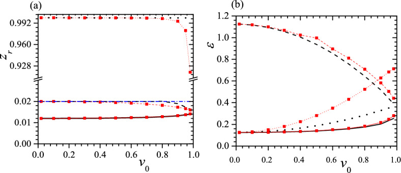
The typical relationships between , and v when , , , and are presented in Fig. 1 in which the blue lines with empty triangle and the black lines are obtained by taking “+" and “−" in Eqs. (5)–(7), respectively.
Figure 1.
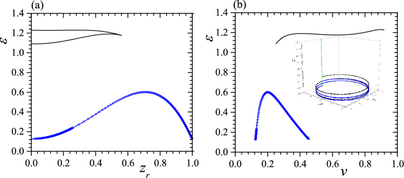
(a) vs. when , , , and , (b) vs. v with the same parameters as in (a). The blue lines with empty triangle and the black lines are obtained by taking “+" and “−" in Eqs. (5)–(7), respectively. The inset in (b) presents three helices with (solid blue with 2 turns), (black dashed with 2 turns) and (green with ball and 1/4 turn). The corresponding free-standing helix has . Reduced units are used.
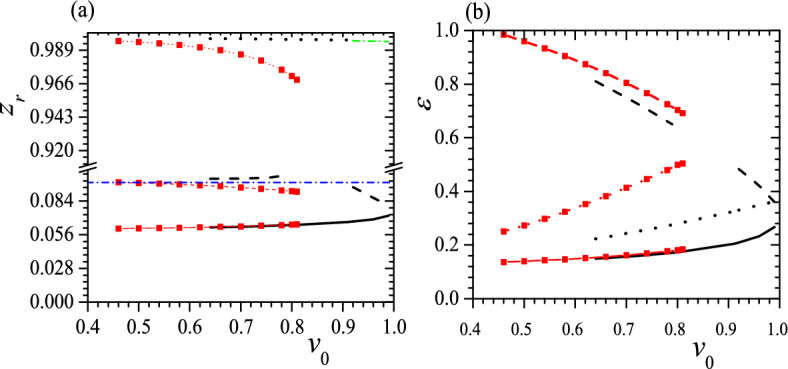
It is not difficult to identify maxima of in Fig. 1, but the minima of is unclear because they are in two edges of curves so in Fig. 2 we enlarge neighborhoods of minima in Fig. 1. From the blue lines in Figs. 1 and 2, we can know that the result obtained from vs. curve agrees with that obtained from vs. v curve, i.e., both curves show two minima and one maximum in and two minima occur at (1) , and ; (2) , and . It gives two stable or metastable helices with significantly different pitches but only a small difference in . In contrast, in black lines of Figs. 1a and 2a, we find one minimum and one maximum in . The minimum occurs at , and so is different that obtained from the blue lines. However, in black lines of Figs. 1b and 2b, we find two minima and two maxima in or there is one more minimum in vs. v curve than that in vs. curve, so clearly this extra minimum in corresponds to a saddle point or a unstable status. In other words, the black lines offer only a low-pitch metastable helix and the metastability is due to a rather high in this status. The calculation of confirms above conclusion, i.e., with this set of parameters the system exhibits a tristable status which is consisted of three stable or metastable helices. Two of three helices have very low pitches (), resembling a circle, while the third has a rather high-pitch (), resembling a straight line. Two low-pitch helices also have considerably different . We also find that the helix with the smallest always exhibits the lowest , making it the GSC of the system. The two higher-pitched helices are then identified as metastable states. Additionally, in this case, the free-standing helix has , positioning it between the s of two confined low-pitch helices. This suggests that the free-standing helix undergoes a split into two low-pitch helices due to anisotropy.
Figure 2.
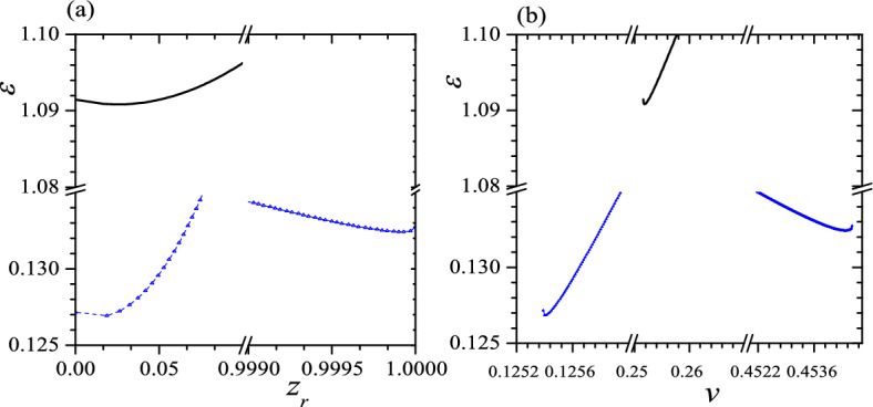
Enlargement of neighborhood of minima in Fig. 1. The symbols are the same as that in Fig. 1. Reduced units are used.
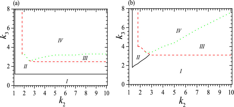
The phase diagrams for the system can be divided into four regimes, as shown in Fig. 3 when , and 0.05. In regime I a helix is unstable or there is only one stable low-pitch helix; regime II has two stable or metastable helices with quite different pitches and it is similar to that of the isotropic system53,54; in regime III there are two stable or metastable low-pitch helices and is clearly different from that in the isotropic system53,54; in regime IV we can find three stable or metastable helices. The tristable status appears when , , and clearly, and in a proper range of . For instance, when , there is not tristable status when and at , and tristable status requires both and . From Fig. 3, we can see that the boundary of different regimes is strongly dependent on . At a small , the threshold of for regime II is almost flat with the variation of , but at a large it increases fast up to a moderate and has no longer bistable status at a large . Meanwhile, the threshold of for regime III decreases slowly with increasing at a small , but at a large it decreases fast with increasing up to a moderate and then becomes flat at a large . Moreover, the threshold of for regime IV is almost flat at a small , but increases almost linear at a larger . In general,the larger the , the larger the required for regimes III and IV as well as the larger the area of regimes I and III. In contrast, the area of regime II shrinks with increasing .
Figure 3.
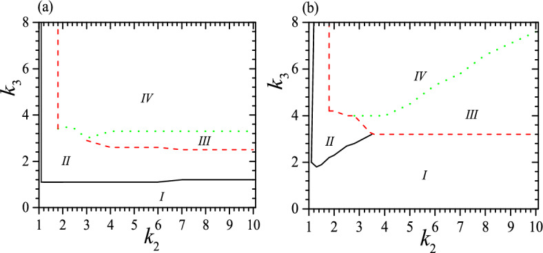
Phase diagrams for the system at and (a) ; (b) . In (a), regime I has not stable helix or has only one stable low-pitch helix and is bound by black solid line, and axis; regime II has two stable or metastable helices with quite different pitches and is enclosed by black solid line, red dashed and green dotted lines; regime III has two stable or metastable low-pitch helices and is enclosed by red dashed and green dotted lines; regime IV is the tristable regime and is bound by red dashed and green dotted lines. In (b), four regimes have the same meaning as that in (a), but regime I is bound by black solid line, , -axis and red dashed line; regime II is enclosed by black solid and red dashed line; regime III is enclosed by red dashed and green dotted lines again; regime IV is also bound by red dashed and green dotted lines. Reduced units are used.
To obtain phase diagrams, for a given set of and , we vary and to solve Eqs. (5), (6) to find the corresponding values of v and . We then substitute these values into Eq. (8) to find relevant , in order to determine whether these parameters offer a stable or metastable state. The lines or boundaries of different regimes in the phase diagrams are determined by .
The regime I is trivial since it is rather easy to obtain the same helix or non-helix in free space, though the parameters are in general different. Regime II is similar to the bistable regime in an isotropic system53, and practically it is much easier to obtain isoenergic bistable status in an isotropic system so that the regime II is less significant. In contrast, regimes III and IV are brand new and denote considerable effect of anisotropy. These two regimes possess a low-pitch but high energy metastable configuration which is absented in an isotropic system53. Due to its increased flexibility, a material with a tristable state should have a broader range of applications than one with a bistable state.
We should note that Fig. 3 illustrates only the necessary conditions for the formation of a tristable status, as it does not take into account the effect of . A complete picture on the stability is also dependent on . For instance, when and , to have a tristable status requires when . Some typical examples for the effect of are presented in Fig. 4 for , , , 3 and 6, as well as , , and 6. We find again that a small favors tristable status, so it appears when and but vanishes when and . Meanwhile, the range of for a tristable status shrinks obviously at a large , as we can see from a comparison between Fig. 4 a and b. Moreover, at a small and up to a moderate , to have a tristable status requires , as we can see from the black dotted lines in Fig. 4a. is almost independent of but it increases with increasing , and can reach a maximum which is dependent on both and . For instance, when , the maximum occurs at with . However, when is rather large ( when ), the range of for a tristable status does not start at , but can begin from a rather large , as we can see from the beginning of red dashed and green solid lines in Fig. 4. Furthermore, at a moderate the range of for a tristable status can reach the maximum, i.e., , and this should be useful because to realize a required or in practical application may be uneasy. Larger does not always favor a larger range of , as we can see from the red dashed and green solid lines in Fig. 4. Our calculations show further that at a moderate and , the tristable regime can be divided into two pieces and between them the helix with a middle pitch is unstable, shown as regimes enclosed by red dashed lines in Fig. 4b. We find further that when , there is no longer a full range of for tristable helix, as shown in Fig. 4b. In a word, the range of for tristable regime is neither a simple function of nor .
Figure 4.
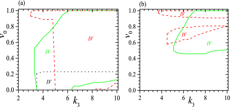
Tristable regime (IV) when and (a) , (black dotted), 3 (red dashed) and 6 (green solid), (b) , (red dashed) and 6 (green solid). The black dotted line and -axis enclose tristable regime for . The red dashed line and -axis enclose tristable regime for . The green solid line and -axis enclose tristable regime for . Different colors of IV correspond to different parameters. Reduced units are used.
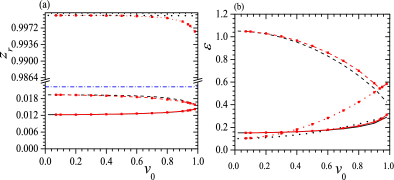
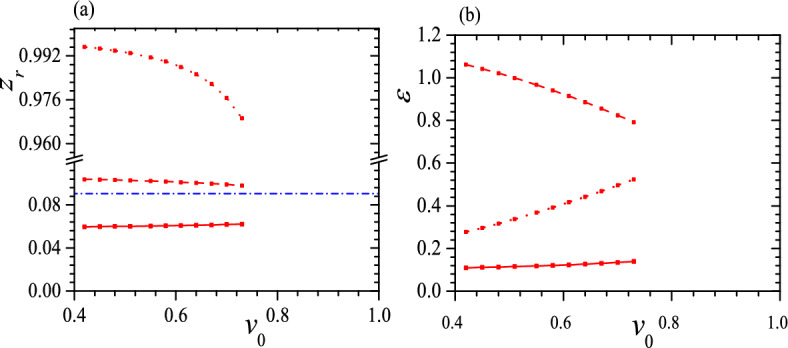
The differences between and of three helices in a tristable status are also crucial, so in Figs. 5 and 6 we present some typical relations between , and when , , 0.05, , and . From these figures, at first, we can see that for both low-pitch helices, and the larger the , the closer the two s, as shown in Figs. 5a and 6a for black solid, black dashed and red solid, red dashed lines. Meanwhile, up to a moderate , two low-pitch helices have a considerable difference in , and the smaller the , the larger the difference in , as shown in Figs. 5b and 6b. Second, for the highest pitch helix and the smaller the , the closer the to 1, so the highest pitch helix is almost indistinguishable from a straight line, as shown in Figs. 5a and 6a. Third, at a small , a large , and , two metastable helices can have the same or in an isoenergic state, shown as the crossovers of two red lines in Fig. 5b and two black lines in Fig. 6b. Fourth, similar to Fig. 4b, at a moderate and , the tristable regime can be divided into two pieces and between them the helix with a middle pitch is unstable, shown as black dashed lines in Fig. 6. Finally, we find that of a free-standing helix is closer to that of the helix with a middle pitch, as shown in Figs. 5a and 6a.
Figure 5.
(a) and (b) vs. for tristable status at , , , (black solid, dashed and dotted lines) and (red solid, dashed and dotted lines with red square). Blue dash-dotted line in (a) represents of a free-standing helix. In both figures, solid lines give the helix with the lowest pitch, dashed lines are correspond to the helix with the middle pitch and dotted lines present the helix with the highest pitch. Reduced units are used.
Figure 6.
(a) and (b) vs. for tristable status at , , , (black solid, dashed and dotted lines) and (red solid, dashed and dotted lines with red square). The meaning of symbols is the same as that in Fig. 5. Reduced units are used.
Together with the result from the isotropic system53, we can figure out the mechanism behind the formation of the tristable state. It arises from the interplay and interdependence of bending, twisting, confinement, and anisotropy. In free space, the natural shape of the filament is a low-pitch helix. Strong confinement favors a straight filament, resulting in a high-pitch helix and leading to a bistable state in the isotropic system. Furthermore, anisotropy is an intrinsic property that tends to alter the inherent configuration, causing a split of the free-standing helix and giving rise to a tristable state.
When and 0.55
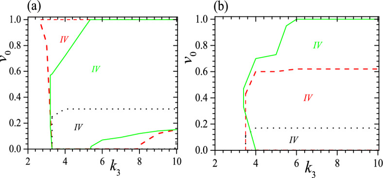
Next we explore the influence of . Phase diagrams for tristable state at , 0.55, and 0.05 are shown in Figs. 7 and 8. Comparing Figs. 7 and 8 with Fig. 3, we can know that the basic characters are similar for three s. In particular, they all have four regimes in phase diagrams and have similar dependence of four regimes on , and . It is also clear that a smaller favors the tristable status, as these figures show that it reduces the required effectively. This fact is confirmed further by examining the dependence of , as shown in Fig. 9 for the system with , 0.55, , , 3 and 6. Comparing Fig. 9 with Fig. 4a, we can find that a smaller enlarges considerably the range of for tristable status. For instance, compared to that at , the area enclosed by red dashed lines increases significantly when but shrinks clearly when . This is a natural result since the strong confinement favors the formation of two higher pitch helices or favors the tristable status.
Figure 7.
Phase diagrams for the system at and (a) , (b) . The meaning of symbols is the same as that in Fig. 3. Reduced units are used.
Figure 8.
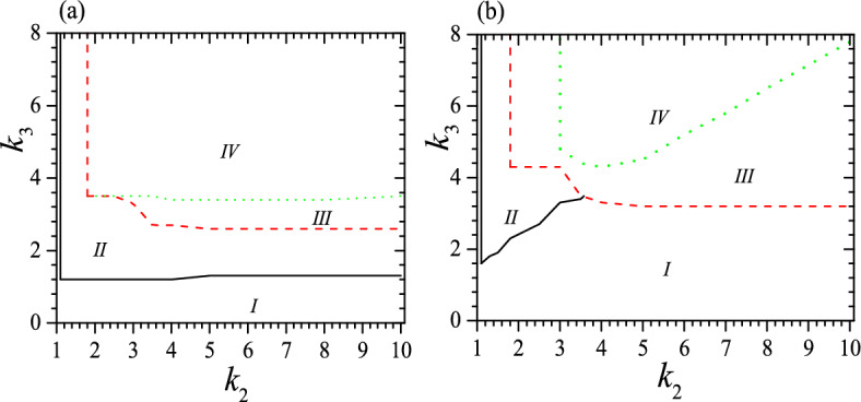
Phase diagrams for the system at and (a) , (b) . The meaning of symbols is the same as that in Fig. 3. Reduced units are used.
Figure 9.
Tristable regimes (IV) when (a), 0.55 (b), , (black dotted), 3 (red dashed) and 6 (green solid). The black dotted line and -axis enclose the tristable regime for . The red dashed line, -axis and enclose the tristable regime for . The green solid line, -axis and enclose the tristable regime for . Different colors of IV correspond to different parameters. Reduced units are used.
Figures 10, 11, 12 and 13 exhibit some typical relations between , and for tristable status when , 0.55, , 0.05, , and . When , , and , the tristable regime is too narrow to illustrate so it disappears in Fig. 13. Comparing Figs. 12 and 13 with Figs. 5 and 6, we can find that different result essentially the same features, except for two special cases. The first significant difference is that when , the lowest pitch helix is not always the GSC, as is the case for and 0.55; instead, the highest pitch helix can become the GSC owing to the stronger confinement, shown as black lines in Figs. 10b and 11b. The second notable difference is that the tristable regime consists of only one piece at because weak confinement disfavors the formation of high-pitch helix, as shown in Fig. 13. Moreover, at some special the GSC becomes an isoenergic state besides a low-pitch metastable helix, or the ground state has two stable helices with the same but quite different , and the smaller the , the smaller the for the isoenergic status, shown as the crossover of black solid line and black dotted line in Figs. 10b and 11b. Again, of a free-standing helix is closer to that of the helix with the middle pitch, as shown in Figs. 10a, 11, 12 and 13a.
Figure 10.
(a) and (b) vs. for tristable status at , , , (black solid, dotted, dashed and dotted lines) and (red solid, dashed and dotted lines with red square). The meaning of symbols is the same as that in Fig. 5. Reduced units are used.
Figure 11.
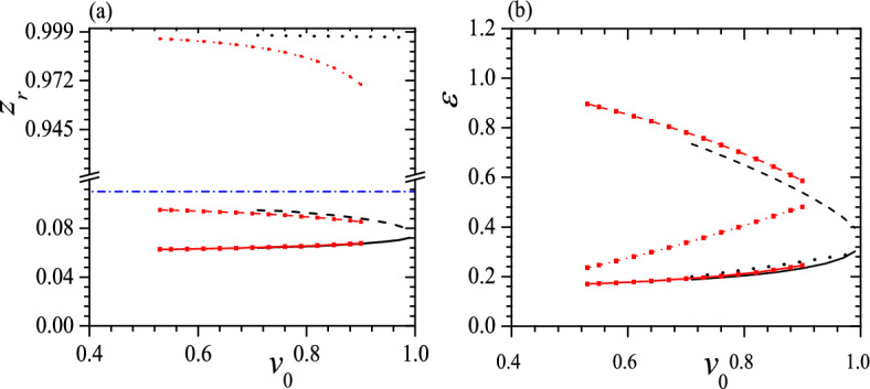
(a) and (b) vs. for tristable status at , , , (black solid, dashed and dotted lines) and (red solid, dashed and dotted lines with red square). The meaning of symbols is the same as that in Fig. 5. Reduced units are used.
Figure 12.
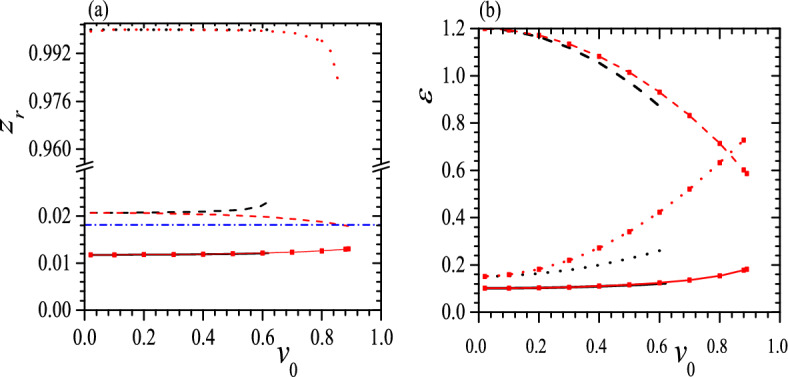
(a) and (b) vs. for tristable status at , , , (black solid) and (red dashed line with red square). The meaning of symbols is the same as that in Fig. 5. Reduced units are used.
Figure 13.
(a) and (b) vs. for tristable status at , and (red dashed line with red square). The meaning of symbols is the same as that in Fig. 5. Reduced units are used.
Discussions
In summary, based on the elastic theory we find a mechanism to form a natural tristable system. Our results demonstrate that when and , confining a helical filament with anisotropic bending rigidities within a cylinder can create a natural tristable state. The tristable state arises from the competition and cooperation among bending, twisting, confinement, and anisotropy. In free space, the natural shape of such a filament is a low-pitch helix. Strong confinement tends to straighten the filament, resulting in a stable high-pitch helix and leading to a bistable state if the system is isotropic. Furthermore, anisotropy induces the split of the low-pitch free-standing helix, ultimately resulting in a tristable state. We anticipate that this mechanism also works in other confinements, such as square or rectangle tubes, even though the stable configuration of the filament may no longer be a helix.
We find that the smaller the , the easier to realize the tristable status. The tristable status is consisted of two low-pitch helices and one high-pitch helix, and these helices can have either nearly the same energy or significantly different energy. The formation of the tristable state also requires a large twisting rigidity and a substantial disparity between two bending rigidities, i.e., a strong anisotropy. The phase diagrams of this system can be divided into four regimes or the system has four distinct statuses. In regime I a helix is unstable or there exists only one stable low-pitch helix; in regime II there are two stable or metastable helices and these two helices have notably different pitches; in regime III there are two stable or metastable low-pitch helices; in regime IV there exists three stable or metastable helices. Regimes III and IV are brand new and exhibit the effect of anisotropy. They possess a low-pitch but high energy metastable configuration which is absented in an isotropic system53. We find that the relative heights of the two low-pitch helices are close to zero, making them resemble a circle, and the larger the , the smaller the difference between two heights. Moreover, up to a moderate , two low-pitch helices have a rather large difference in energy, and the smaller the , the larger the difference. Meanwhile, the height of the high-pitch helix is almost indistinguishable from a straight line. We also find that at a small , a large , and , two higher pitch helices can possess the same or the filament can be in a metastable isoenergic state. Finally, at some special the GSC of the system is in an isoenergic state, i.e., the tristable status has two stable helices with the same but significant different , in addition to a low-pitch metastable helix.
While our results are based on the elastic model and may appear to have limited relation to real materials, they still provide valuable insights for identifying relevant materials. From our results, intuitionally, to have a tristable state, in free space the free-standing helix should exhibit two distinct visible characters: (1) a non-circular or non-square crosssection, resulting in a large ; (2) a low-pitch, leading to a small . Many nanotubes or proteins, such as actin and actin complexes, exhibit both of these two characteristics. In accord with these two characters, we can first rule out MreB and its homologs since they are intrinsically straight. Additionally, a tristable system requires . It was reported that tandem sequence repeats of approximately 126 adenine tracts in dsDNA can yield a circle structure48,49. This gives rise to nm, which is much smaller than nm. As a result, constructing a tristable system using dsDNA is impractical unless some bases can be removed to achieve a smaller and a larger .
Finally, our findings are valid to both macroscopic and microscopic systems, but the microscopic version, i.e., a nano-filament under nanoconfinement, should be more significant. Due to its increased flexibility, a material exhibiting natural tristable behavior would have a broader range of applications than one with bistable characteristics, making this new system particularly intriguing. This natural tristable system may also offer a prospective green metamaterial since it does not need to consume energy to maintain one of its three stable or metastable configurations. Owing to the inherent chiral symmetry of a helix, this tristable system may exhibit remarkable optical properties, potentially becoming optically active materials capable of producing a wider range of colors than a bistable material. In particular, we can expect to control the output color by adjusting the length of the helix. In this system, the shape of the high-pitch helix is almost a straight line so the transition between three configurations is analogous to the alignment transition from parallel normally white mode to twisted helical mode found in nematic liquid crystal molecules that ushered in the era of liquid crystal color displays. Moreover, the substantial disparity in energy within a tristable status may be utilized for high-density energy storage.
Appendix: Expressions for static equations and stability criterion
From Eqs. (2)–(4), we can find the explicit forms of static equations as follows,
| 9 |
| 10 |
Equations (9) and (10) are second order nonlinear differential equations but it is straightforward to find their s-independent solutions, as given by Eqs. (5)-(6).
Let , , where and are independent, and keep the terms up to the first order of and , Eqs. (9) and (10) become
| 11 |
| 12 |
where ’s are also independent and
| 13 |
| 14 |
| 15 |
| 16 |
| 17 |
| 18 |
| 19 |
Assuming and , where and are again independent, Eqs. (11) and (12) become
| 20 |
Now demanding and , we obtain a quadratic equation of , i.e.,
| 21 |
| 22 |
If both , then the helix is at least metastable because all ’s are imaginary so and will remain small at an arbitrary s, or a small disturbance on the filament cannot induce a serious deviation from the helical configuration. Otherwise, the helix is unstable since at least one Re( so both and will increase rapidly with increasing s, and the filament will deviate considerably from a helix at large s, even if both and are small. Therefore, can serve as a stability criterion to assess the stability of a helix.
Author contributions
The author contributed to the study conception, design, methodology, data collection and analysis, writing and approved the final manuscript.
Funding
This work has been supported by the National Science and Technology Council of the Republic of China through Grant No. NSTC 112-2112-M-032-011.
Data availability
The data that support the findings of this study are available from the corresponding author upon reasonable request.
Competing interests
The author declares no competing interests.
Footnotes
Publisher's note
Springer Nature remains neutral with regard to jurisdictional claims in published maps and institutional affiliations.
References
- 1.Restrepo, D., Mankame, N. D. & Zavattieri, P. D. Phase transforming cellular materials. Extreme Mech. Lett.4, 52–60. 10.1016/j.eml.2015.08.001 (2015). [Google Scholar]
- 2.Alturki, M. & Burgueño, R. Multistable cosine curved dome system for elastic energy dissipation. J. Appl. Mech.86, 091002. 10.1115/1.4043792 (2019). [Google Scholar]
- 3.Fu, K., Zhao, Z. & Jin, L. Programmable granular metamaterials for reusable energy absorption. Adv. Funct. Mater.29, 1901258. 10.1002/adfm.201901258 (2019). [Google Scholar]
- 4.Pan, F. et al. 3D pixel mechanical metamaterials. Adv. Mater.31, 1900548. 10.1002/adma.201900548 (2019). [DOI] [PubMed] [Google Scholar]
- 5.Sun, S., An, N., Wang, G., Li, M. & Zhou, J. Snap-back induced hysteresis in an elastic mechanical metamaterial under tension. Appl. Phys. Lett.115, 091901. 10.1063/1.5119275 (2019). [Google Scholar]
- 6.Raney, J. R., Nadkarni, N., Daraio, C. & Bertoldi, K. Stable propagation of mechanical signals in soft media using stored elastic energy. Proc. Natl. Acad. Sci USA113, 9722–9727. 10.1073/pnas.1604838113 (2016). [DOI] [PMC free article] [PubMed] [Google Scholar]
- 7.Preston, D. J., Rothemund, P., Jiang, H. J. & Whitesides, G. M. Digital logic for soft devices. Proc. Natl. Acad. Sci USA116, 7750–7759. 10.1073/pnas.1820672116 (2019). [DOI] [PMC free article] [PubMed] [Google Scholar]
- 8.Song, Y. et al. Additively manufacturable micro-mechanical logic gates. Nat Commun.10, 882. 10.1038/s41467-019-08678-0 (2019). [DOI] [PMC free article] [PubMed] [Google Scholar]
- 9.Yasuda, H., Tachi, T., Lee, M. & Yang, J. Origami-based tunable truss structures for non-volatile mechanical memory operation. Nat Commun.8, 962. 10.1038/s41467-017-00670-w (2017). [DOI] [PMC free article] [PubMed] [Google Scholar]
- 10.Yu, K., Fang, N. X., Huang, G. & Wang, Q. Magnetoactive acoustic metamaterials. Adv. Mater.30, 1706384. 10.1002/adma.201706348 (2018). [DOI] [PubMed] [Google Scholar]
- 11.Kim, Y., Yuk, H., Zhao, R., Chester, S. A. & Zhao, X. Printing ferromagnetic domains for untethered fast-transforming soft materials. Nature558, 274–279. 10.1038/s41586-018-0185-0 (2018). [DOI] [PubMed] [Google Scholar]
- 12.Pendry, J. B., Schurig, D. & Smith, D. R. Controlling electromagnetic fields. Science312, 1780–1782. 10.1126/science.1125907 (2006). [DOI] [PubMed] [Google Scholar]
- 13.Schurig, D., Mock, J. J., Justice, B. J., Cummer, S. A., Pendry, J. B., Starr. A. F. & Smith, D. R. Metamaterial electromagnetic cloak at microwave frequencies. Science314, 977-980 10.1126/science.1133628 (2006). [DOI] [PubMed]
- 14.Wegener, M. Metamaterials beyond optics. Science342, 939–940. 10.1126/science.1246545 (2013). [DOI] [PubMed] [Google Scholar]
- 15.Xu, C., Stiubianu, G. T. & Gorodetsky, A. A. Adaptive infrared-reflecting systems inspired by cephalopods. Science359, 1495–1500. 10.1126/science.aar5191 (2018). [DOI] [PubMed] [Google Scholar]
- 16.Maldovan, M. Sound and heat revolutions in phononics. Nature503, 209–217. 10.1038/nature12608 (2013). [DOI] [PubMed] [Google Scholar]
- 17.Han, T. et al. Experimental demonstration of a bilayer thermal cloak. Phys. Rev. Lett.112, 054302. 10.1103/PhysRevLett.112.054302 (2014). [DOI] [PubMed] [Google Scholar]
- 18.Xu, L., Yang, S. & Huang, J. Passive metashells with adaptive thermal conductivities: Chameleonlike behavior and its origin. Phys. Rev. Appl.11, 054071. 10.1103/PhysRevApplied.11.054071 (2019). [Google Scholar]
- 19.Carrella, A., Brennan, M. J. & Waters, T. P. Static analysis of a passive vibration isolator with quasi-zero-stiffness characteristic. J. Sound Vib.301, 678–689. 10.1016/j.jsv.2006.10.011 (2007). [Google Scholar]
- 20.Nicolaou, Z. G. & Motter, A. E. Mechanical metamaterials with negative compressibility transitions. Nat. Mater.11, 608. 10.1038/nmat3331 (2012). [DOI] [PubMed] [Google Scholar]
- 21.Lakes, R. S. Negative-Poisson’s-ratio materials: Auxetic solids. Annu. Rev. Mater. Res.47, 63–81. 10.1146/annurev-matsci-070616-124118 (2017). [Google Scholar]
- 22.Mirzaali, M. J. et al. Rational design of soft mechanical metamaterials: Independent tailoring of elastic properties with randomness. Appl. Phys. Lett.111, 051903. 10.1063/1.4989441 (2017). [Google Scholar]
- 23.Frenzel, T., Kadic, M. & Wegener, M. Three-dimensional mechanical metamaterials with a twist. Science358, 1072–1074. 10.1126/science.aao4640 (2017). [DOI] [PubMed] [Google Scholar]
- 24.Lipton, J. I. et al. Handedness in shearing auxetics creates rigid and compliant structures. Science360, 632–635. 10.1126/science.aar4586 (2018). [DOI] [PubMed] [Google Scholar]
- 25.Schaedler, T. A. et al. Ultralight metallic micro lattices. Science334, 962–965. 10.1126/science.1211649 (2011). [DOI] [PubMed] [Google Scholar]
- 26.Han, S. C., Lee, J. W. & Kang, K. A new type of low density material: Shellular. Adv. Mater.27, 5506–5511. 10.1002/adma.201501546 (2015). [DOI] [PubMed] [Google Scholar]
- 27.Zheng, X. et al. Ultralight, ultrastiff mechanical metamaterials. Science344, 1373–377. 10.1126/science.1252291 (2014). [DOI] [PubMed] [Google Scholar]
- 28.Meza, L. R., Das, S. & Greer, J. R. Strong, lightweight, and recoverable three-dimensional ceramic nanolattices. Science345, 1322–1326. 10.1126/science.1255908 (2014). [DOI] [PubMed] [Google Scholar]
- 29.Zhang, X. et al. Three-dimensional high entropy alloy-polymer composite nanolattices that overcome the strength recoverability trade-off. Nano Lett.18, 4247–4256. 10.1021/acs.nanolett.8b01241 (2018). [DOI] [PubMed] [Google Scholar]
- 30.Schadt, M. & Helfrich, W. Voltage-dependent optical activity of a twisted nematic liquid crystal. Appl. Phys. Lett.18, 127–128. 10.1063/1.1653593 (1971). [Google Scholar]
- 31.Yang, D.-K. & Wu, S.-T. Fundamental of Liquid Crystal Devices 2nd edn. (Wiley, 2014). 10.1002/9781118751992. [Google Scholar]
- 32.Esue, O., Wirtz, D. & Tseng, Y. GTPase activity, structure, and mechanical properties of filaments assembled from bacterial cytoskeleton protein MreB. J. Bacteriol.188, 968–976. 10.1128/JB.188.3.968-976.2006 (2006). [DOI] [PMC free article] [PubMed] [Google Scholar]
- 33.Jones, L. J. F., Carballido-López, R. & Errington, J. Control of cell shape in bacteria: Helical, actin-like filaments in Bacillus subtilis. Cell104, 913–922. 10.1016/s0092-8674(01)00287-2 (2001). [DOI] [PubMed] [Google Scholar]
- 34.Daniel, R. A. & Errington, J. Control of cell morphogenesis in bacteria: Two distinct ways to make a rod-shaped cell. Cell113, 767–776. 10.1016/S0092-8674(03)00421-5 (2003). [DOI] [PubMed] [Google Scholar]
- 35.Vats, P. & Rothfield, L. Duplication and segregation of the actin (MreB) cytoskeleton during the prokaryotic cell cycle. Proc. Natl. Acad. Sci. USA104, 17795–17800. 10.1073/pnas.0708739104 (2007). [DOI] [PMC free article] [PubMed] [Google Scholar]
- 36.Tanaka, M. et al. Ratchetlike motion of helical bilayers induced by boundary constraints. Phys. Rev. E.106, L012605. 10.1103/PhysRevE.106.L012605 (2022). [DOI] [PubMed] [Google Scholar]
- 37.Love, A. E. H. A Treatise on the Mathematical Theory of Elasticity (Cambridge University Press, 2013). 10.1038/105511a0. [Google Scholar]
- 38.Nizette, M. & Goriely, A. Towards a classification of Euler–Kirchhoff filaments. J. Math. Phys.40, 2830–2866. 10.1063/1.532731 (1999). [Google Scholar]
- 39.Yamakawa, H. & Yoshizaki, T. Helical Wormlike Chains in Polymer Solutions (Springer, Berlin, 1996). 10.1007/978-3-642-60817-9. [Google Scholar]
- 40.Zhou, Z. Novel relationships between some coordinate systems and their effects on mechanics of an intrinsically curved filament. J. Phys. Commun.2, 035008. 10.1088/2399-6528/aab21c (2018). [Google Scholar]
- 41.Panyukov, S. V. & Rabin, Y. Thermal fluctuations of elastic filaments with spontaneous curvature and torsion. Phys. Rev. Lett.85, 2404–2407. 10.1103/PhysRevLett.85.2404 (2000). [DOI] [PubMed] [Google Scholar]
- 42.Panyukov, S. V. & Rabin, Y. Fluctuating elastic rings: Statics and dynamics. Phys. Rev. E64, 011909. 10.1103/PhysRevE.64.011909 (2001). [DOI] [PubMed] [Google Scholar]
- 43.Smith, B., Zastavker, Y. V. & Benedek, G. B. Tension-induced straightening transition of self-assembled helical ribbons. Phys. Rev. Lett.87, 278101. 10.1103/PhysRevLett.87.278101 (2001). [DOI] [PubMed] [Google Scholar]
- 44.Kessler, D. A. & Rabin, Y. Stretching instability of helical springs. Phys. Rev. Lett.90, 024301. 10.1103/PhysRevLett.90.024301 (2003). [DOI] [PubMed] [Google Scholar]
- 45.Zhou, Z. & Lai, P.-Y. Elasticity and stability of a helical filament. Phys. Rev. E71, 052801. 10.1103/PhysRevE.71.052801 (2005). [DOI] [PubMed] [Google Scholar]
- 46.Allard, J. F. & Rutenberg, A. D. Pulling helices inside bacteria: Imperfect helices and rings. Phys. Rev. Lett.102, 158105. 10.1103/PhysRevLett.102.158105 (2009). [DOI] [PubMed] [Google Scholar]
- 47.Dlakic, M., Park, K., Griffith, J. D., Harvey, S. C. & Harrington, R. E. The organic crystallizing agent 2-methyl-2,4-pentanediol reduces DNA curvature by means of structural changes in A-tracts. J. Biol. Chem.271, 17911–17919. 10.1074/jbc.271.30.17911 (1996). [DOI] [PubMed] [Google Scholar]
- 48.Han, W., Lindsay, S. M., Dlakic, M. & Harrington, R. E. Kinked DNA. Nature (London)386, 563. 10.1038/386563a0 (1997). [DOI] [PubMed] [Google Scholar]
-
49.Han, W., Dlakic, M., Zhu, Y.-J., Lindsay, S. M. & Harrington, R. E. Strained DNA is kinked by low concentrations of Zn
 . Proc. Natl. Acad. Sci. USA94, 10565–10570. 10.1073/pnas.94.20.10565 (1997).
[DOI] [PMC free article] [PubMed] [Google Scholar]
. Proc. Natl. Acad. Sci. USA94, 10565–10570. 10.1073/pnas.94.20.10565 (1997).
[DOI] [PMC free article] [PubMed] [Google Scholar] - 50.Drew, H. R. & Travers, A. A. DNA bending and its relation to nucleosome positioning. J. Mol. Biol.186, 773–790. 10.1016/0022-2836(85)90396-1 (1985). [DOI] [PubMed] [Google Scholar]
- 51.Moukhtar, J., Fontaine, E., Faivre-Moskalenko, C. & Arnéodo, A. Probing persistence in DNA curvature properties with atomic force microscopy. Phys. Rev. Lett.98, 178101. 10.1103/PhysRevLett.98.178101 (2007). [DOI] [PubMed] [Google Scholar]
- 52.Konikoff, F. K., Chung, D. S., Donovan, J. M., Small, D. M. & Carey, M. C. Filamentous, helical, and tubular microstructures during cholesterol crystallization from bile. Evidence that cholesterol does not nucleate classic monohydrate plates. J. Clin. Invest.90, 1155–1160. 10.1172/JCI115935 (1992). [DOI] [PMC free article] [PubMed] [Google Scholar]
- 53.Zhou, Z. Bistability of a helical filament confined on a cylinder. Phys. Rev. E.105, 024502. 10.1103/PhysRevE.105.024502 (2022). [DOI] [PubMed] [Google Scholar]
- 54.Zhou, Z. Mechanical instability of a bistable helical filament confined on a cylinder. Chin. J. Phys.79, 395. 10.1016/j.cjph.2022.09.008 (2022). [Google Scholar]
- 55.Tanaka, F. & Takahashi, H. Elastic theory of supercoiled DNA. J. Chem. Phys.83, 6017–6026. 10.1063/1.449637 (1985). [Google Scholar]
- 56.Goldstein, H. Classical Mechanics 3rd edn. (Addison-Wesley, 2002). 10.1002/9780470972502. [Google Scholar]
- 57.Zhou, Z. Crucial role of the intrinsic twist rate for the size of an intrinsically curved semiflexible biopolymer. Phys. Rev. E.102, 032405. 10.1103/PhysRevE.102.032405 (2020). [DOI] [PubMed] [Google Scholar]
- 58.Marko, J. F. & Siggia, E. D. Fluctuations and supercoiling of DNA. Science265, 506. 10.1126/science.8036491 (1994). [DOI] [PubMed] [Google Scholar]
- 59.Moukhtar, J., Fontaine, E., Faivre-Moskalenko, C. & Arnéodo, A. Probing persistence in DNA curvature properties with atomic force microscopy. Phys. Rev. Lett.98, 178101. 10.1103/PhysRevLett.98.178101 (2007). [DOI] [PubMed] [Google Scholar]
Associated Data
This section collects any data citations, data availability statements, or supplementary materials included in this article.
Data Availability Statement
The data that support the findings of this study are available from the corresponding author upon reasonable request.