Abstract
The most common surgical procedure to manage the malunion of the bones is corrective osteotomy. The current gold standard for securing the bone segments after osteotomy is the use of titanium plates and allografts which have disadvantages such as possible allergic reaction, additional operations such as extraction of the graft from other sites and removal operation. The utilization of resorbable materials presents an opportunity to mitigate these drawbacks but has not yet been thoroughly researched in the literature. This study assesses the viability of using biodegradable, 3D-printed patient-specific implants made of Poly(-L-lactide-co-D, L-lactide) (PLDLLA) and β-Tricalcium Phosphate (β-TCP) as an alternative material in an in-vitro biomechanical study involving ex vivo biomechanical compression testing, biodegradation testing, and calorimetric measurements. These implants possess a unique shape, resembling a wedge and are fixated as a connection between the osteotomised bone using resorbable screws. Following point-of-care virtual planning, bio-mechanical compressive tests with (n = 5) ex vivo radii equipped with PLDLLA/ β-TCP implants were performed to prove sufficient stability of the connection. All PLDLLA/ β-TCP implants withstood a compressive force of at least 1ʼ211 N which exceeds the maximum force reported in literature in case of a fall from the height of one meter. Furthermore, the results showed a consistent surface chemistry and slow degradation rate. The outcomes are encouraging, establishing the groundwork for an innovative distal radius corrective osteotomy surgical method. However, further research is necessary to thoroughly evaluate the long-term biodegradability and mechanical efficacy of the implants.
Keywords: Distal radius fracture, Distal radius malunion, Corrective osteotomy, Bioresorbable composite, 3D-printing, Patient-specific implants
Introduction
Distal radius fractures constitute 8–17% of all bone fractures and up to 72% of all forearm fractures and are therefore the most commonly occurring fractures in the human body [1, 2]. In the United States of America alone, two hundred thousand people suffer from it every year [3]. Post-treatment complications still occur despite the wide range of treatment methods available. Distal radius fracture treatments include closed treatment with casting, intrafocal pinning, non-bridging or bridging external fixation, arthroscopically assisted external fixation, open reduction, and internal fixation, among many others [3]. Malunion is the most frequent complication of the distal radius fracture [4]. These malunions of the distal radius are usually caused by the improper or misaligned healing of the fracture. The correct alignment of the distal radius is essential for the normal operation of the wrist. The distal radius serves as the base for the radioscaphoid, radioulnate, and distal radioulnar joints, which are the joints responsible for wrist articulations. Radial deformities alter the biomechanics of the wrist and have the potential to have several detrimental outcomes such as pain, limited mobility, hand weakness, dysfunction, or arthritis [1].
Corrective osteotomy, a popular surgical method to treat the malunion of the bones, aims to remodel the bone such that its architecture and the anatomy of the joints are reversed back to the normal, healthy state. A titanium plate placed over the gap and screwed into the bone is currently the gold standard for stabilizing the bones following an osteotomy procedure. According to the Ministry of Health, Labour, and Welfare in Japan, titanium is utilized in 95% of all orthopaedic implants and 70% of all surgical implants [5].
However, using titanium has several drawbacks. When used for fixation, it offers a highly rigid connection that leaves little room for flexibility, which might cause problems with a child’s bone development [6]. According to studies, there is a chance of plate migration, temperature sensitivity at the implant site, the screws’ palpability, and discomfort. Cases of allergic reactions to titanium are uncommon but have been reported [7]. The use of titanium increases the risk of osteoporosis in the surrounding bone tissue. A major drawback is the necessity of an additional removal surgery. All surgeries carry risks, removals of plates can be complicated, and breakage can occur, making it impossible for the entirety of the material to be removed [6, 8–10]. Alternate materials such as polyetheretherketone (PEEK) or bioresorbable materials are currently being investigated to substitute titanium [11, 12].
The use of bioresorbable materials has increased in popularity in orthopaedics and maxillofacial surgery due to their numerous advantages over the use of titanium and autografts. Special attention has been paid to composite materials comprising polymers and calcium phosphates. Studies that compared products made of a single material to those made of polymer and calcium phosphate composites, showed that the latter can produce products of higher quality. For instance, mechanical properties can be tailored to the physiological needs and stress shielding can be eliminated by modifying the mechanical characteristics. Moreover, the deterioration rate may be changed to provide the implant’s desired stability [12]. To eliminate the detrimental effect on children’s bone development, the stiffness of the fixation with the use of bioresorbable material can be adjusted. In contrast to metals, polymers and calcium phosphates do not cause thermal sensitivity. Moreover, the stress is gradually transmitted to the bone as a result of the deterioration process and, since the implant will completely degrade over time, there’s no longer a need for a second surgery. The radiolucency of the polymers is another benefit, making imaging simpler and avoiding any potential artifacts. Moreover, growth factors can be progressively released from biodegradable materials to promote healing or reduce infection or inflammation [10].
The implants are readily manufactured utilizing 3D-printing technology, allowing for the creation of different forms for patient-specific use [10]. One of the biggest advantages of the 3D-printing technology is its cost-effectiveness. When compared to conventional methods, the amount of material utilized to create 3D-printed models is substantially lower [13]. The use of subtractive methods requires a block of material that is larger in all three dimensions than the finished product. This creates a lot of waste and naturally drives up the price of the material. Manufacturing complicated geometries is another excellent benefit of 3D-printing. Due to the limiting capabilities of the subtraction technology, layer-by-layer printing techniques enable users to create objects with intricate internal and exterior geometry that would be difficult to fabricate using conventional methods.
Additional focus should be paid to the fixation method of the implant. Regardless of the material, the external plates which are screwed to the bone can be palpable, which is a negative effect often mentioned by the patients. Alternative methods of fixating the bone grafts shall be explored, therefore, the design of the implants needs to be altered. Some studies were carried out with the use of implants that do not require any external plates. Instead, bone grafts made of β-TCP containing multiple spikes, sometimes known as spacers, have been employed. It is believed that the spikes can adequately fixate the region within the osteotomy site, following a classical medial opening wedge high tibial osteotomy. Studies on cadavers have demonstrated that the construct’s stability is sufficient. There have also been reports of clinical instances. The spacers’ short-term examination produced positive results, however long-term studies are yet to be performed [14, 15]. To the best of the authors’ knowledge, this approach has not yet been performed for malunion of the distal radius treatment.
In this study, a similar approach using wedges for corrective osteotomies distal radius malunions with the use of screws shall be investigated. Four Thiel’s method preserved cadaver forearms with no record of malunion were used in a biomechanical study to evaluate the strength of the connection made with the novel surgical technique and one fixed using a gold standard method. Moreover, real time and accelerated degradation studies in phosphate buffer solution were performed to assess the degradation rate, resorbability propagation as well as surface chemistry of the implants. Loss on ingnition study was performed to assess the ratio of organic and inorganic components of the composite. Lastly, calorimetry study was performed to assess whether the manufacturing process affects physical properties of the material.
Materials and methods
Planning, printing, specimen preparation
Virtual planning
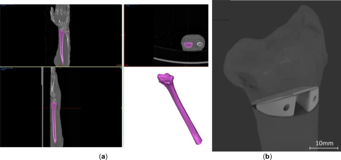
The cadaver forearm (left and right radii of two donors, referred to as 1 L, 1R, 2 L and 2R and left radius of a third donor, referred to as SP, later fixed with a standard plate (SP)). The cadaver forearm “imaging was performed…” was performed using SIEMENS Biograph 128 scanner with an in-plane resolution of 0.25 mm × 0.25 mm and a slice thickness of 0.37 mm. Post implantation CT scans were performed using SIEMENS Symbia Intevo 16 with an 0.29 × 0.29 mm resolution and a slice thickness of 0.6 mm. Segmentation of the radii was done using Materialise Mimics 23.0 software (Materialise NV, Leuven, Belgium, Fig. 1). Virtual osteotomy planning was performed in accordance with the indications of the gold standard presented by Baumbach et al. with the proximal cutting surface perpendicular to the axis of the diaphysis [16]. The angle of osteotomy was 35 degrees. Incomplete osteotomies were performed, leaving the anterior cortical bone intact. Wedge-shaped patient-specific implants (WSPSI) were designed using Autodesk Fusion 360 v2.0.15050 (Autodesk, Inc., San Rafael, California, United States) software. Clearance in the range of 0.5 mm has been kept from the posterior side to ensure no protrusion of the implants past the bone extents. Each of the WSPSIs was required to accommodate 16 mm long Arthrex bio compression screws (Arthrex GmbH, Munich, Germany) with a linearly increasing diameter ranging from 3 mm to 3.7 mm. Holes of the diameter of 2 mm were modelled to make a guide for the predrilling of the 3 mm diameter holes at a later stage. Each pair of WSPSIs has screw holes going in two opposite directions, that is, for the lateral WSPSI, the hole goes to the distal part of the radius, while for the medial one the screw is attached to the proximal part of the radius.
Fig. 1.
(a) Segmentation of the distal radius geometry based on the computed tomography data of the ex vivo sample SP (b) Virtual surgical plan of corrective osteotomy of the distal radius and implants for sample 1 L
Manufacturing process
The WSPSIs were produced using Arburg Plastic Freeforming (APF) with the Arburg Freeformer 200-3X (Arburg GmbH + Co KG, Lossburg, Germany). The APF method can process thermoplastic materials by combining injection molding and 3D-printing technology. The following literature describes the APF and parameter optimization process [17–19]. The material of choice was Resomer® LR 706 S (Evonik Operations GmbH, Darmstadt, Germany), comprising 70% Poly(-L-lactide-co-D, L-lactide) 70:30 (PLDLLA) and 30% β-Tricalcium Phosphate (β-TCP). According to the manufacturer, PLDLLA/β-TCP meets the biocompatibility testing requirements in accordance with DIN EN ISO 10993-1:2003. Armat11 (Arburg GmbH + Co KG, Lossburg, Germany) was used as a support material. The printing parameters are listed in Table 1.
Table 1.
Printing parameters for PLDLLA/β-TCP
| Parameter | Value | Unit |
|---|---|---|
| Zone 1 temperature | 40 | °C |
| Zone 2 temperature | 180 | °C |
| Zone 3 temperature | 200 | °C |
| Nozzle temperature | 205 | °C |
| Chamber temperature | 70 | °C |
| Drop aspect ratio | 1.19 | - |
| Discharge rate | 65 | % |
| Droplet overlap | 30 | % |
| Filling angle | 45 | % |
| Layer height | 0.2 | mm |
| Scaling factor X | 0.9975 | - |
| Scaling factor Y | 0.9900 | - |
| Scaling factor Z | 0.9275 | - |
Specimen preparation and biomechanical tests
The printed specimens underwent predrilling using a milling machine with a drill diameter of 3 mm and subsequently, a sterilisation process was performed by an in-house low-temperature sterilisation system Steris V-Pro (STERIS Corporation, OH, USA). H2O2 plasma sterilisation of the WSPSIs was performed at the temperature of 55 °C, using fast cycle mode of 19 min. The osteotomies were performed by an experienced surgeon specialised in hand surgery. Following a careful extraction of the bones from the surrounding soft tissues, a rotational saw was used for cutting. WSPSIs were installed within the osteotomy sites using Arthrex bio compression screws (Arthrex GmbH, Munich, Germany). Additional bone grafts were not used. Radius SP was fixed using a conventional plate, which is a current golden standard in orthopaedics (dorsal frame plate from the 2018 Product catalogue, Medartis AG, Basel, Switzerland).
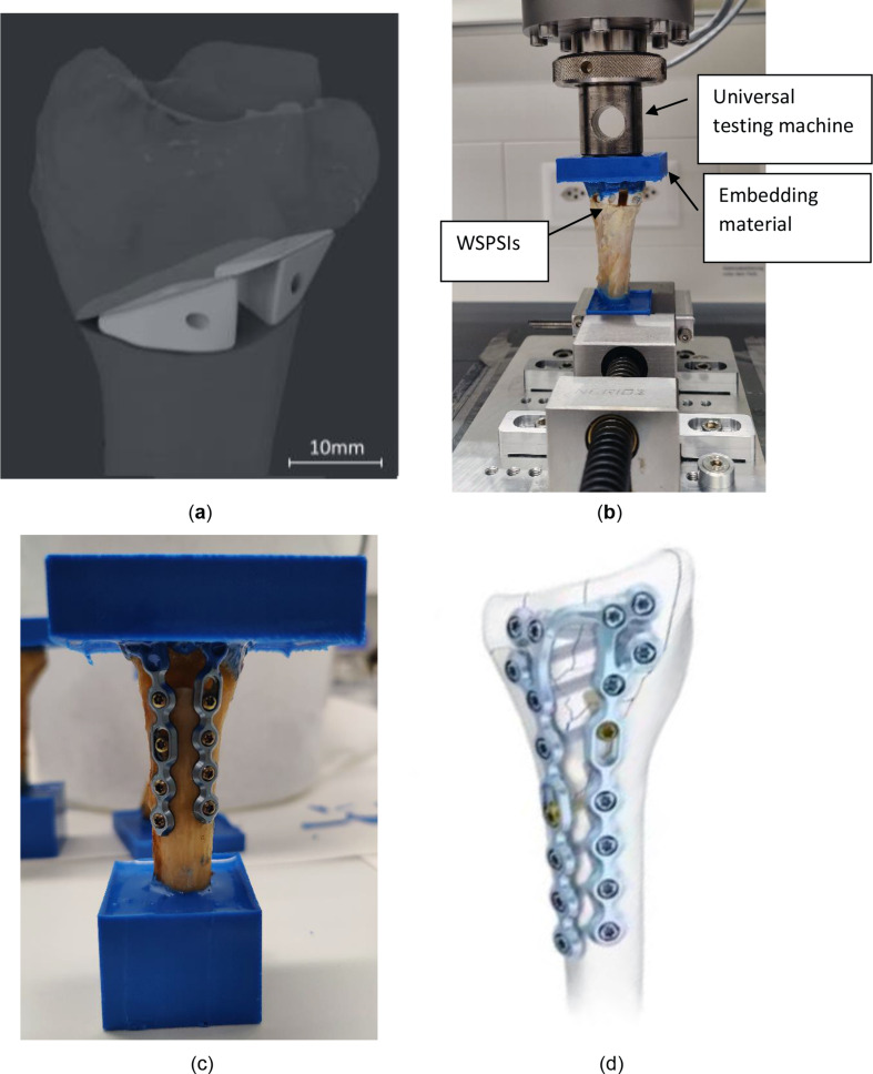
Following the implantation, the radii were shortened to a total length of 10 cm from the tip of the styloid process to the cut location. Both the proximal and distal parts of the radii were fixed within a resin RenCast® CW20 (Huntsman Corporation, Texas, United States) to fit the clamp of the test machine and ensure equal load distribution across the distal part of the radius. The radii were mounted in a universal testing machine (Z020, Zwick/Roell, Ulm, Germany) and loaded axially at the temperature of 22 °C with a speed of 1 mm/min until fracture (See Fig 2).
Fig. 2.
(a) Specimen 1R - virtual planning, (b) Specimen 1R embedded for fracture load testing (c) Specimen SP embedded (d) standard osteotomy plate by Medartis AG [31]
Conducted research
Biodegradability study
For the real-time and accelerated biodegradability studies, WSPSIs for specimen 1 L were chosen. 24 sets of WSPSIs were printed and divided into the following 7 batches:
Non-degraded specimens as control (6 sets).
Real time (37 °C) degraded specimens, degradation time of 24 h (3 sets).
Real time (37 °C) degraded specimens, degradation time of 72 h (3 sets).
Degraded specimens (50 °C), degradation time of 1 week (3 sets).
Degraded specimens (50 °C), degradation time of 2 weeks (3 sets).
Degraded specimens (50 °C), degradation time of 3 weeks (3 sets).
Degraded specimens (50 °C), degradation time of 4 weeks (3 sets).
For degradation testing, the WSPSIs did not possess a screw hole, as the assumption has been made that the screws would block the access of fluids into the implants. The specimens were dried to a constant mass using a desiccator, under a vacuum for at least 5 days, and weighed using a balance (Mettler Toledo XPE206, Columbus, Ohio, United States). The WSPSIs were submerged in 40 ml of phosphate buffer solution (PBS), consisting of 18.2%vol. potassium dihydrogen phosphate (1/15 mol/l KH2PO4) and 81.8%vol. disodium hydrogen phosphate (1/15 mol/l Na2HPO4) (PBS) in 50 ml tight containers. The ratio of the PBS volume, to the test specimen mass, was kept greater than 30:1 to ensure that the pH values stayed in the range of 7.4 ± 0.2 throughout the tests. For real-time degradation, the specimens submerged in the PBS were kept in an incubator at 37 °C. Three specimens were incubated for 24 h, the other three for 72 h. Accelerated degradation specimens submerged in the PBS were kept in a bath with the temperature set to 50 °C. Three specimens were designated for each test period, i.e. 1 week, 2 weeks, 3 weeks, and 4 weeks. The values of the pH were measured weekly.
The rate of aging factor is calculated according to the formula suggested by Hukins et al. [20]:
 |
1 |
Where:
f: rate of aging factor.
ΔT: difference of temperatures between applicable temperature and test temperature.
The aging factor f describes the rate of aging. For instance, the increase from the applicable temperature of 37 °C to the testing temperature of 50 °C would be equivalent to an aging factor of  ≈ 2.5. With this temperature increase, the 1, 2, 3, and 4 week degradation would correspond to 2.5-, 5-, 7.5- and 10-weeks degradation, respectively.
Mass loss study
Following the degradation study, the specimens were dried in a desiccator for at least five days and their mass was measured. Due to the instant moisture soaking of the filter papers with possible debris, their mass has been omitted due to imprecise measurements. The mass of the degraded samples in grams was obtained.
Loss on ignition study
The ratio of organic and inorganic components was evaluated by inserting the specimens into a furnace to a program in which they were initially heated up to 200 °C for 10 min, followed by the increase of the temperature to 520 °C at which the specimens remained for 60 min.
Calorimetry
Calorimetry was performed using TAM III-48 (TAinstruments, Delaware, USA). Samples have been heated up at the rate of 2 °C/h. Curve fitting (Split Pearson 7 function) was performed using Fityk software (Marcin Wojdyr, Poland).
Light microscopy
Light microscope Wild M7A (Leica Microsystems AG, Heerbrugg, Switzerland) was used together with LAS V4.7 software.
Scanning electron microscopy and energy dispersive X-ray analysis
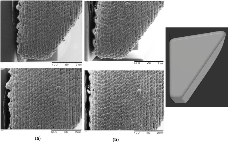
For the assessment of the WSPSI’s degradation effects on the implant surface and metallic abrasion during the printing process scanning electron microscopy (SEM) and energy dispersive X-ray analysis (EDX) were performed using the TM3030Plus (Hitachi, Tokyo, Japan). SEM images were performed at the magnification of 30× at the voltage of 5 kV for 120 s (Fig. 3). No coating was applied to the specimens before the examination.
Fig. 3.
30× magnified SEM image of (a) Non degraded sample, (b) 4 weeks accelerated degradation sample
Results
Biomechanical study
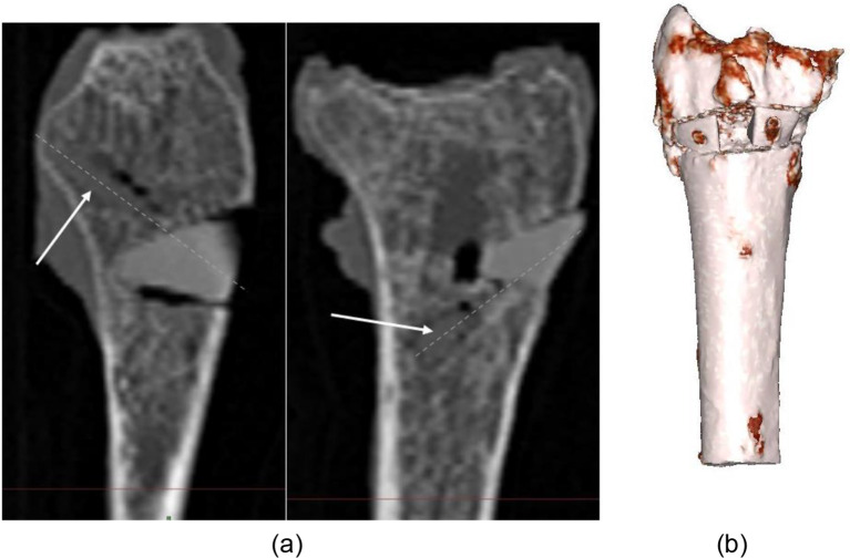
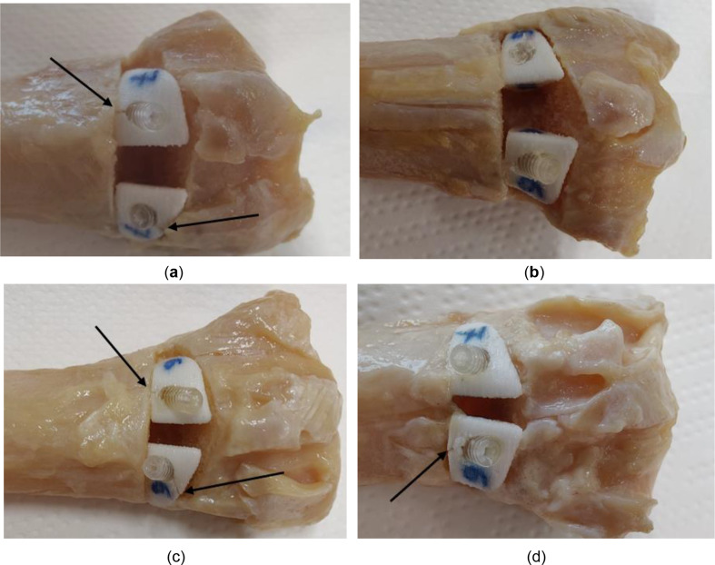
During virtual planning of the implants, the design of the wedges was performed such that the shape of the wedges fit the osteotomy site well and the connection was stable, while achieving the planned correction angle of 35 degrees. After the fixation of the WSPSIs, no relative motion between the implants and the bones was observed following the introduction of the bioresorbable compression screws. The post-implantation CT images were taken to assess the screw positions and revealed a minor gap formation between bone and implant (Figs. 4 and 5). However, in certain cases, excessive bearing pressure was exerted on the previously predrilled holes during the installation of the screws, leading to the development of a crack that spread from the border of the hole outwards (Fig. 5). It is advised that either longer distances should be maintained between the hole and the implant’s edge, or a screw with a smaller diameter should be utilized. The size of the implants and, thus, the greatest achievable distances between the edge of the holes and the extent of the implants are influenced by the angle of the osteotomy and the radius size. Each situation requires a preliminary investigation to determine the viability of the strategy. Furthermore, it appears that the connection to the proximal part of the radius is more susceptible to cracking than the connection to the distal part.
Fig. 4.
(a) Post-implantation CT scan of 1 L, screw anchoring. Dashed lines indicate the axis of the screw, (b) 3D reconstruction of post-implantation 1 L
Fig. 5.
Indication of cracks in the WSPSIs following the introduction of the bio compression screws: specimen (a) 1 L, (b) 1R, (c) 2 L, (d) 2R
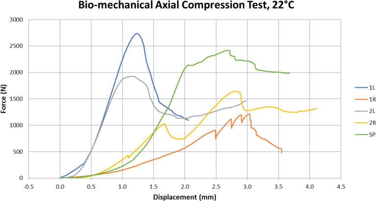
In specimen 1R, the connection shows a gap between one of the WSPSI and the proximal plane of the osteotomy on the medial part of the connection. The compression screw’s forces appear to have caused the WSPSI to rotate away from the desired position. Figure 6 shows the force–displacement curve of the axial compression test. Table 2 summarizes the forces and maximum displacements at the maximum force for all specimens. As can be seen in Fig. 6, an excellent loading behaviour was shown with the 1 L specimen. The connection maintained its stability and the screws did not come loose or dislocate. The cortical bone behind the WSPSIs fractured at a force of 2ʼ736.4 N (See Fig 6).
Fig. 6.
The force-displacement curve of the axial compression test
Table 2.
Maximum force and displacement at maximum force for each test specimen
| Radius | Implant Type | Maximum Force (N) | Displ. at Max. Force (mm) |
|---|---|---|---|
| 1 L | WSPSI | 2’736.42 | 1.22 |
| 1R | WSPSI | 1’211.01 | 3.03 |
| 2 L | WSPSI | 1’927.45 | 1.17 |
| 2R | WSPSI | 1’643.92 | 2.81 |
| SP | Standard Plate | 2’415.55 | 2.69 |
For sample 1R, numerous drops in reaction force were observed throughout the loading process before the force reached its maximum value. This indicates that while being loaded, the connection continued to adjust to transfer the loads more efficiently. As previously indicated, these findings may have been impacted by the gap in the medial portion of the connection. At 1ʼ211 N the connection between the screw of the readjusting implant and the spongy bone was disrupted and the WSPSI failed to support the osteotomy site.
For specimen 2 L, the maximum force of 1’927.45 N was observed.
The WSPSI of 2R experienced a readjustment at a force level of 414.7 N. However, this was not classified as a loss of implant stability. A decrease in force at a level of 1ʼ008.5 N. was observed. Due to a significant increase of force following this incident, it is presumed to be linked to the crushing of the styloid process tip, which in this case was protruding through the distal embedding. The compression screw of the lateral WSPSI broke its connection and the WSPSI dislocated in the dorsal direction at the point at which the highest force of 1ʼ643.9 N was measured.
The maximum force withstood by the SP was 2ʼ415.6 N. The breaking mechanism was the same as in the case of 1 L.
Biodegradability study
Tables 3 and 4 present the average pH values for real and accelerated degradation samples. The pH readings were within the range of 7.4 ± 0.2, thus, no adjustments were necessary.
Table 3.
pH values for real-time degradation specimens for sample 1 L (n = 3)
| Specimen | pH |
|---|---|
| 1 (24 h) | 7.46 |
| 2 (24 h) | 7.46 |
| 3 (24 h) | 7.46 |
| 1 (72 h) | 7.47 |
| 2 (72 h) | 7.47 |
| 3 (72 h) | 7.47 |
Table 4.
Average pH values for accelerated degradation specimens for sample 1 L (n = 3)
| Specimen | Average pH | Std. Dev. |
|---|---|---|
| 1 (1w) | 7.39 | 0 |
| 2 (1w) | 7.39 | 0 |
| 3 (1w) | 7.39 | 0 |
| 1 (2w) | 7.46 | 0.01 |
| 2 (2w) | 7.48 | 0.01 |
| 3 (2w) | 7.49 | 0.02 |
| 1 (3w) | 7.48 | 0.04 |
| 2 (3w) | 7.47 | 0.04 |
| 3 (3w) | 7.47 | 0.04 |
| 1 (4w) | 7.50 | 0.08 |
| 2 (4w) | 7.51 | 0.08 |
| 3 (4w) | 7.51 | 0.08 |
SEM investigation
SEM analysis of the sides of the specimens from the control batch and the 4 weeks accelerated degradation batch was performed to analyse the degradation propagation.
The results of the SEM examination on the propagation of deterioration (Fig. 3) were inconclusive. According to the upper images in Fig. 3 (a) and (b), it can be claimed that the intervals between the layers and between the subsequent drops appear deeper/larger in the case of the 4-week deteriorating specimen. Yet, the lower image depicts the opposite scenario. The gaps in the control specimen are smaller and the 4-week degraded specimen appears smoother. Because of the manufacturing process, the surface is not uniform, making it unreliable to investigate the surface for degradation propagation direction.
EDX investigation
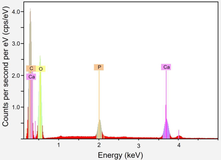
An EDX analysis revealed no metallic nozzle particles (Table 5). Through the deterioration process, the spectrum stays largely consistent. Due to the composite nature of the material, which has been measured in certain cases to have greater levels of surface TCP, minor changes may be noticeable. Figure 8 presents an example spectrum. Table 6 summarizes the findings for each degradation period.
Table 5.
EDX investigation results of the accelerated degradation samples
| Degradation Period | C (atom-%) | O (atom-%) | Ca (atom-%) | P (atom-%) |
|---|---|---|---|---|
| Control | 56.87 | 40.83 | 1.43 | 0.87 |
| 24 h | 58.85 | 38.79 | 1.56 | 0.80 |
| 72 h | 56.31 | 41.15 | 1.58 | 0.95 |
| 1 week | 56.61 | 40.57 | 1.88 | 0.94 |
| 2 weeks | 56.05 | 41.57 | 1.49 | 0.88 |
| 3 weeks | 56.36 | 40.98 | 1.68 | 0.97 |
| 4 weeks | 56.07 | 41.35 | 1.62 | 0.96 |
Fig. 8.
EDX investigation of accelerated 4 weeks degradation sample
Table 6.
Mass loss investigation results
| Specimen* | Initial mass (mg) | Mass after degradation (mg) | Mass loss (mg) | Average m/l type specimens (mg) | Average all specimens (mg) | Mass loss (%) | Average m/l type specimens (%) | Average all specimens [%] |
|---|---|---|---|---|---|---|---|---|
| 2(24 h)l | 541.90 | 541.89 | 0.01 | 0.01 | 0.01 | 0.002 | 0.020 | 0.002 |
| 3(24 h)l | 528.62 | 528.61 | 0.01 | 0.002 | ||||
| 2(24 h)m | 640.10 | 640.10 | 0.00 | 0.01 | 0.000 | 0.015 | ||
| 3(24 h)m | 637.65 | 637.63 | 0.02 | 0.003 | ||||
| 2(72 h)l | 541.62 | 541.46 | 0.16 | 0.15 | 0.16 | 0.030 | 0.028 | 0.026 |
| 3(72 h)l | 543.24 | 543.10 | 0.14 | 0.026 | ||||
| 2(72 h)m | 636.49 | 636.34 | 0.15 | 0.16 | 0.024 | 0.025 | ||
| 3(72 h)m | 654.08 | 653.91 | 0.17 | 0.026 | ||||
| 2(1w)l | 549.67 | 549.89 | -0.22 | -0.69 | -0.86 | -0.040 | -0.129 | -0.144 |
| 3(1w)l | 533.43 | 534.59 | -1.16 | -0.217 | ||||
| 2(1w)m | 637.74 | 638.16 | -0.42 | -1.02 | -0.066 | -0.159 | ||
| 3(1w)m | 644.42 | 646.04 | -1.62 | -0.251 | ||||
| 2(2w)l | 554.47 | 554.95 | -0.48 | –0.61 | -0.66 | -0.087 | -0.112 | -0.112 |
| 3(2w)l | 542.30 | 543.04 | -0.74 | -0.136 | ||||
| 2(2w)m | 623.90 | 624.85 | -0.95 | -0.70 | -0.152 | -0.112 | ||
| 3(2w)m | 632.47 | 632.92 | -0.45 | -0.071 | ||||
| 2(3w)l | 554.47 | 543.67 | -0.95 | -1.14 | -1.34 | -0.175 | -0.209 | -0.224 |
| 3(3w)l | 542.30 | 548.17 | -1.33 | -0.243 | ||||
| 2(3w)m | 623.90 | 640.65 | -1.13 | -1.54 | -0.177 | -0.239 | ||
| 3(3w)m | 632.47 | 648.76 | -1.95 | -0.301 | ||||
| 2(4w)l | 552.73 | 555.31 | -2.58 | -2.24 | -2.48 | -0.467 | -0.408 | -0.413 |
| 3(4w)l | 545.68 | 547.58 | -1.90 | -0.348 | ||||
| 2(4w)m | 651.76 | 654.86 | -3.10 | -2.67 | -0.476 | -0.419 | ||
| 3(4w)m | 642.21 | 644.53 | -2.32 | -0.361 |
*l/m indicates lateral/medial WSPSI
Mass loss study
Mass loss investigation has been performed for each time period. Table 6 summarises all the measurements and shows the calculated mass loss (positive values) or mass gain (negative values).
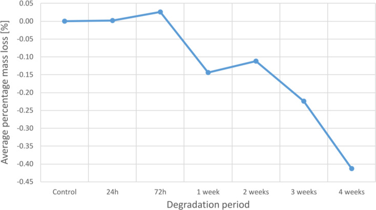
An analysis of average mass loss reveals a general pattern of increasing total mass with increasing deterioration time. Although larger specimens often lose more mass than smaller specimens, the proportion of mass loss is typically similar for the two types of WSPSIs. The average percent mass loss at 24 and 72 h is 0.002% and 0.026%, respectively. However, a percentage mass increase of 0.144%, 0.112%, 0.224%, and 0.413% is seen from 1 to 4 weeks of degradation.
Figure 7 presents the average percentage mass loss at each degradation period.
Fig. 7.
Average mass loss at each degradation period
Loss on ignition
Loss on ignition study has been performed for each degradation period and control. The results are summarized in Table 7 and (See Table 6).
Table 7.
Loss on ignition investigation results
| Specimen* | Mass after degradation (mg) | Mass of the container (mg) |
Mass specimen + container after Ignition study (mg) |
Inorganic content (%) | Average (%) | ||
|---|---|---|---|---|---|---|---|
| 2(control)l | 545.51 | 8ʼ277.92 | 8ʼ443.74 | 30.397 | 29.602 | ||
| 2(control)m | 641.53 | 8ʼ282.85 | 8ʼ468.10 | 28.876 | |||
| 3(control)l | 549.92 | 8ʼ219.83 | 8ʼ382.24 | 29.533 | |||
| 2(24 h)l | 541.89 | 8ʼ226.26 | 8ʼ385.70 | 29.423 | 29.422 | ||
| 2(24 h)m | 640.10 | 8ʼ162.34 | 8ʼ350.57 | 29.406 | |||
| 3(24 h)l | 528.61 | 8ʼ162.51 | 8ʼ318.11 | 29.436 | |||
| 2(72 h)l | 541.46 | 8ʼ187.18 | 8ʼ345.79 | 29.293 | 29.322 | ||
| 2(72 h)m | 636.34 | 8ʼ213.95 | 8ʼ400.62 | 29.335 | |||
| 3(72 h)l | 543.10 | 8ʼ187.42 | 8ʼ346.76 | 29.339 | |||
| 2(1w)l | 549.89 | 8ʼ234.00 | 8ʼ396.75 | 29.597 | 29.587 | ||
| 2(1w)m | 638.16 | 8ʼ219.83 | 8ʼ409.25 | 29.682 | |||
| 3(1w)l | 534.59 | 8ʼ233.81 | 8ʼ391.41 | 29.481 | |||
| 2(2w)l | 554.95 | 8ʼ233.07 | 8ʼ395.97 | 29.354 | 29.401 | ||
| 2(2w)m | 624.85 | 8ʼ226.15 | 8ʼ409.84 | 29.397 | |||
| 3(2w)l | 543.04 | 8ʼ277.92 | 8ʼ437.85 | 29.451 | |||
| 2(3w)l | 543.67 | 8ʼ277.75 | 8ʼ436.81 | 29.257 | 29.266 | ||
| 2(3w)m | 640.65 | 8ʼ234.06 | 8ʼ421.56 | 29.267 | |||
| 3(3w)l | 548.17 | 8ʼ282.85 | 8ʼ443.33 | 29.276 | |||
| 2(4w)l | 555.31 | 8ʼ282.54 | 8ʼ444.58 | 29.180 | 29.237 | ||
| 2(4w)m | 654.86 | 8ʼ213.97 | 8ʼ405.17 | 29.197 | |||
| 3(4w)l | 547.58 | 8ʼ219.83 | 8ʼ380.45 | 29.333 |
*l/m indicates lateral/ medial WSPSI
The average inorganic content tends to decline from 0 h (control) to 72 h of degradation. In comparison to the control, the average inorganic content of the 24- and 72-hour specimens showed a 0.61% and 0.95% reduction, respectively. Yet, with a drop of just 0.05%, 1-week degraded specimens contained a nearly identical amount of inorganic material as the controls. The inorganic content then steadily decreases once again with increasing degradation time, with corresponding degradation rates of 0.68%, 1.14%, and 1.23% for 2 weeks, 3 weeks, and 4 weeks compared to the control.
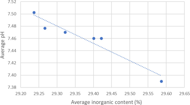
The ratio of the organic to inorganic components is not significantly affected by the length of PBS exposure. However, a dependency has been found between the average pH level and average inorganic content. A linear dependency between pH values and the inorganic content has been plotted in Fig. 9.
Fig. 9.
Linear dependency between pH values and the inorganic content
Calorimetry
The measured glass transition temperature of the samples (n = 12) was 50.26 ± 0.44 °C and lower than specified by the manufacturer, that is, 60 °C [21].
Discussion
From the initial CT scan to implantation, the entire virtual planning process, performed at the point of care, was highly reliable and posed no issues or unforeseen challenges. The accuracy of the CT images allowed a trustworthy segmentation using the available software. In the majority of cases, the WSPSIs’ original design matched the osteotomy site well. The only case in which the gap occurred was due to overly high torque applied during the screw insertion. However, specimens 1 L and 1R showed higher compressive strength in the biomechanical test, despite crack formation of the implants, indicating that the appearance of cracks due to screw pressure may not have a significant impact on the overall compressive strength during the bench test. To prevent future cracks caused by high bearing pressure, the placement of the WSPSIs’ holes can be modified. Additionally, one could investigate the cutting of matching threads using a screw tap to increase the stability between implant and screw. Alternatively, screws of smaller size might be used. Due to polymer strength limitations another bioresorbable material, such as magnesium [22], might be used, however, further research must be done to determine the viability of the new solution.
The implants were successfully printed with medical-grade material. In this study, we focused mainly on the mechanical stability of the wedges. According to the results of the biomechanical study in Table 2, the construction can bear a force of at least 1ʼ211 N. Many studies have been conducted to evaluate the forces occurring on the wrists while falling. For instance, the experiment by DeGoede et al. demonstrated that during a fall, the peak forces reach values of 1ʼ021 ± 161 N when the shoulders are one meter above the ground [23]. Based on our results, the novel surgical method seems to be a promising approach for use in patients as, even in a fall scenario, the peak forces do not reach the connection strength’s lowest values. However, we have not yet investigated the biological response to the implant material.
Polyesters based on lactic acid have been intensively researched for more than four decades for their biodegradable properties and their suitability for bone regeneration [24]. For the successful healing of the distal radius bone after corrective osteotomy, it is important to provide not only sufficient mechanical strength but also increase osteoconductivity and absorbability. Poly lactic acids are suitable for use for implants with medium mechanical strength, but lack bone bonding capabilities [24]. To improve bioactivity and osteointegration, certain inorganic additives such as β-TCP are frequently used [25]. Biodegradable poly lactic acids, such as PLDLLA copolymers, and osteoconductive additives such as β-TCP have been intensively researched independently and in combination [23–26]. These studies have shown PLDLLA/TCP composites to have good biocompatibility and mechanical properties close to bone.
To enhance the potential of healing and control the strength of the connection, additional design adjustments can be made, such as the incorporation of lattices or surface preparation [29, 30]. To promote osteogenesis, the option of seeding the construct with cells or growth factors (such as bone mineral protein-BMP or transforming growth factors-TGF), can be investigated. Some limitations, however, have to be considered. First, the investigation’s primary flaw is that the force has only been applied axially. The worst-case scenario of the connection has been tested, that is when the connection is the weakest due to not yet established bone ingrowth into an implant. However, axial forces are not the only loads acting on the wrists, especially rotational forced need to be considered in future research. Further tests with an increased number of experimental samples must be performed to evaluate the build’s capacity to withstand torsion, bending moments, and shear stresses, which, given the geometry of the construct, may be essential in establishing the viability of the solution. Fatigue testing of the samples and in vivo testing in animals should be considered in the future to investigate further investigate the mechanical stability and biological response in comparison to bone plate fixation, which is the current standard.
Since ceramic materials tend to have higher hardness than commercially used metals, the possibility of abrasion of the nozzle, during 3D-printing, via the composite was one of the crucial points of investigation. An EDX analysis revealed no metallic nozzle particles. It proves that the β-TCP can be safely printed without endangering patients to metal exposure of the machine feeding track. It also showed that the surface chemistry stays relatively constant throughout the degradation process which is important for cell adhesion. A further investigation shall be done to assess the adhesion and proliferation of the cells on the scaffold created by the APF-manufactured implant.
The mass-loss study revealed a gradual increase of mass of up to approx. 0.4 wt%, which is likely caused by precipitation of hydroxyapatite or other compounds on the implant surface during the immersion in the PBS [27]. The ratio of the organic-inorganic components was not significantly affected by the length of PBS exposure, but rather was related to the average pH level. The inorganic content level rises with increasing pH, suggesting that the PLDLLA part of the implant will degrade more quickly even with only a minor pH fall within the permitted range, or a pH of 7.4 ± 0.2. It is possible to draw the conclusion that the average inorganic content and pH values are related. The inorganic content is more pronounced in samples that have been deteriorated for one week or longer and increases as the average pH value decreases. As a result, a graph was made to display the relationship between the two variables.
To demonstrate the linear relationship between the pH value and the average inorganic concentration, a linear fitting has been done. The inorganic content decreases as the average pH increases. Reduced pH has a small impact on the β-TCP while having a significant impact on the rate of polymer breakdown. The resorption of the β-TCP is cell-mediated, where the β-TCP is reabsorbed as a result of the low pH fields of acid species generated by cells [28]. In the biodegradation study, there are no cells present in the PBS solution. No discernible β-TCP resorption is observed, suggesting that the small pH fluctuations are inadequate to damage the ceramic.
The calorimetry study revealed that the glass transition temperature has been significantly affected compared to the manufacturer’s specification. It reveals that the physical characteristics of the material are altered during the 3D-printing manufacturing process by heating the material over the melting point. The material pellets underwent mechanical and thermal processing in order for the specimens to be printed. They were kept at a temperature of 205 °C and under the pressure of 200 MPa. Nevertheless, the glass transition temperature, at 50.26 °C, remained significantly higher than body temperature. This suggests that the material is safe for implantation; however, caution is advised for subsequent post-processing and sterilization procedures involving temperatures beyond the glass transition point as they could change the material composition and stability.
In summary, the novel approach for the treatment of distal radius malunions have shown sufficient compressive and degradation stability, and could, based on the results reported in this study, be a viable option, in which the use of standard titanium plates, and, therefore, a second removal surgery, can be omitted. The results are promising, laying the foundation for an innovative surgical approach to distal radius corrective osteotomy.
Conclusion
The novel implant designs for fixation of distal radius corrective osteotomy were successfully 3D-printed, sterilized and displayed sufficient compressive strength to withstand the equivalent force of a fall from a height of one meter. The elemental composition of the implant surface revealed no metallic particles from the feeding track of the 3D printer. The surface chemistry remained a constant level throughout the degradation process, which are favourable circumstances for cell adhesion. Nevertheless, the WSPSI biological response and mechanical properties throughout the degradation process remains to be investigated.
Acknowledgements
The authors would like to thank Nadja Rohr and Sabrina Karlin, Biomaterials and Technology, University Center for Dental Medicine Basel for providing the materials and laboratory support to conduct the fracture load and degeneration testing.
Author contributions
Conceptualization: AJ, MM, MMG, PH; Fund raising: MM, AG, MK, FT; Investigation: AJ, MM, PH; Methodology: AJ, MM, FT, MK, AG, PH; Formal analysis: AJ, MM, PH; Writing – original draft: AJ, MM; Writing – review & editing: MMG, MK, FT, AG, PH.
Funding
This work has been supported by Innovation Booster Additive Manufacturing - IBAM: 2021-08 and by the Werner Siemens Foundation through the Minimally Invasive Robot-Assisted Computer-guided LaserosteotomE (MIRACLEII) project.
Data availability
No datasets were generated or analysed during the current study.
Declarations
Ethics approval and consent to participate
All cadavers/involved human material met the requirements for consent according to Art. 36 HFG. In addition, the Ethical Commission of Northwestern Switzerland has reviewed the documents of our project (EKNZ AO_2023-00058) and confirmed that it fulfils the general ethical and scientific standards for research with humans.
Consent for publication
Not applicable.
Further disclosure
Part of or the entire set of findings have been presented during the master defense of Adam Jakimiuk.
Competing interests
The authors declare no competing interests.
Footnotes
Publisher’s note
Springer Nature remains neutral with regard to jurisdictional claims in published maps and institutional affiliations.
Adam Jakimiuk and Michaela Maintz contributed equally to this work.
References
- 1.Bushnell BD, Bynum DK. Malunion of the distal Radius. J Am Acad Orthop Surg. Jan. 2007;15(1):27–40. 10.5435/00124635-200701000-00004. [DOI] [PubMed]
- 2.Pogue DJ, et al. Effects of distal radius fracture malunion on wrist joint mechanics. J Hand Surg Am. Sep. 1990;15(5):721–7. 10.1016/0363-5023(90)90143-F. [DOI] [PubMed]
- 3.Liporace FA, Adams MR, Capo JT, Koval KJ. Distal Radius fractures. J Orthop Trauma. Nov. 2009;23(10):739–48. 10.1097/BOT.0b013e3181ba46d3. [DOI] [PubMed]
- 4.Katt B, Seigerman D, Lutsky K, Beredjiklian P. Distal Radius Malunion. J Hand Surg Am. May 2020;45(5):433–42. 10.1016/j.jhsa.2020.02.008. [DOI] [PubMed]
- 5.Hanawa T. Titanium–tissue interface reaction and its control with Surface Treatment. Front Bioeng Biotechnol. Jul. 2019;7. 10.3389/fbioe.2019.00170. [DOI] [PMC free article] [PubMed]
- 6.Bell RB, Kindsfater CS. The Use of Biodegradable plates and screws to stabilize facial fractures. J Oral Maxillofac Surg. Jan. 2006;64(1):31–9. 10.1016/j.joms.2005.09.010. [DOI] [PubMed]
- 7.Müller K, Valentine-Thon E. Hypersensitivity to titanium: clinical and laboratory evidence. Neuro Endocrinol Lett. Dec. 2006;27(Suppl 1):31–5. Erratum in: Neuro Endocrinol Lett. Oct. 2007;28(5):iii. PMID: 17261997. [PubMed]
- 8.Dhillon M, Prabhakar S, Prasanna C. Preliminary experience with biodegradable implants for fracture fixation. Indian J Orthop. 2008;42(3):319. 10.4103/0019-5413.41856. [DOI] [PMC free article] [PubMed] [Google Scholar]
- 9.Kumar AV, Staffenberg DA, Petronio JA, Wood RJ. Bioabsorbable Plates and Screws in Pediatric Craniofacial Surgery, Journal of Craniofacial Surgery, vol. 8, no. 2, pp. 97–99, Mar. 1997, 10.1097/00001665-199703000-00006 [DOI] [PubMed]
- 10.Turvey TA, Bell RB, Phillips C, Proffit WR. Self-Reinforced Biodegradable Screw Fixation Compared With Titanium Screw Fixation in Mandibular Advancement, Journal of Oral and Maxillofacial Surgery, vol. 64, no. 1, pp. 40–46, Jan. 2006, 10.1016/j.joms.2005.09.011 [DOI] [PMC free article] [PubMed]
- 11.Di Maggio B, et al. PEEK radiolucent plate for distal radius fractures: multicentre clinical results at 12 months follow up. Injury. Oct. 2017;48:S34–8. 10.1016/S0020-1383(17)30655-1. [DOI] [PubMed]
- 12.Toda E et al. Jan., Feasibility of Application of the Newly Developed Nano-Biomaterial, β-TCP/PDLLA, in Maxillofacial Reconstructive Surgery: A Pilot Rat Study, Nanomaterials, vol. 11, no. 2, p. 303, 2021, 10.3390/nano11020303 [DOI] [PMC free article] [PubMed]
- 13.Berman B. 3-D printing: The new industrial revolution, Bus Horiz, vol. 55, no. 2, pp. 155–162, Mar. 2012, 10.1016/j.bushor.2011.11.003
- 14.Zhang R et al. Jul., Open-Wedge HTO with Absorbable β-TCP/PLGA Spacer Implantation and Proximal Fibular Osteotomy for Medial Compartmental Knee Osteoarthritis: New Technique Presentation, Journal of Investigative Surgery, vol. 34, no. 6, pp. 653–661, 2021, 10.1080/08941939.2019.1670296 [DOI] [PubMed]
- 15.Deng X, et al. Changes in patellar height and posterior tibial slope angle following uniplanar medial opening wedge high tibial osteotomy using a novel wedge-shaped spacer implanation concurrent with proximal partial fibulectomy. Int Orthop. Jan. 2021;45(1):109–15. 10.1007/s00264-020-04786-5. [DOI] [PubMed]
- 16.Baumbach SF, et al. Assessment of a novel biomechanical fracture model for distal radius fractures. BMC Musculoskelet Disord. Dec. 2012;13(1):252. 10.1186/1471-2474-13-252. [DOI] [PMC free article] [PubMed]
- 17.Hentschel L, Kynast F, Petersmann S, Holzer C, Gonzalez-Gutierrez J. Processing conditions of a medical Grade Poly(Methyl Methacrylate) with the Arburg Plastic Freeforming Additive Manufacturing process. Polym (Basel). 2020;12:2677. 10.3390/polym12112677. [DOI] [PMC free article] [PubMed] [Google Scholar]
- 18.Engler LG, Crespo JS, Gately NM, Major I, Devine DM. Process optimization for the 3D Printing of PLA and HNT composites with Arburg Plastic Freeforming. J Compos Sci. Oct. 2022;6(10). 10.3390/jcs6100309.
- 19.Bayart M et al. Aug., Pellet-Based Fused Filament Fabrication (FFF)-Derived Process for the Development of Polylactic Acid/Hydroxyapatite Scaffolds Dedicated to Bone Regeneration, Materials, vol. 15, no. 16, 2022, 10.3390/ma15165615 [DOI] [PMC free article] [PubMed]
- 20.Hukins DWL, Mahomed A, Kukureka SN. Accelerated aging for testing polymeric biomaterials and medical devices, Med Eng Phys, vol. 30, no. 10, pp. 1270–1274, Dec. 2008, 10.1016/j.medengphy.2008.06.001 [DOI] [PubMed]
- 21.Evonik N. & Care GmbH, RESOMER® Composite LR 706 S ß-TCP Technical Data Sheet. 2019.
- 22.Kozakiewicz M. Change in Pull-Out Force during resorption of Magnesium Compression screws for Osteosynthesis of Mandibular Condylar fractures. Materials. Jan. 2021;14(2):237. 10.3390/ma14020237. [DOI] [PMC free article] [PubMed]
- 23.DeGoede KM, Ashton-Miller JA. Fall arrest strategy affects peak hand impact force in a forward fall, J Biomech, vol. 35, no. 6, pp. 843–848, Jun. 2002, 10.1016/S0021-9290(02)00011-8 [DOI] [PubMed]
- 24.Lin F-H, Chen -Mo, Lin -Pin, Lee J. The Merit of Sintered PDLLA/TCP composites in Management of Bone Fracture Internal fixation. Blackwell Science, Inc; 1999. [DOI] [PubMed]
- 25.Prabhu B, Karau A, Wood A, Dadsetan M, Liedtke H, DeWitt T. Bioresorbable materials for Orthopedic Applications (Lactide and Glycolide Based). In: Li B, Webster T, editors. in Orthopedic Biomaterials: Progress in Biology, Manufacturing, and industry perspectives. Cham: Springer International Publishing; 2018. pp. 287–344. 10.1007/978-3-319-89542-0_13. [Google Scholar]
- 26.Smit TH, Krijnen MR, van Dijk M, Wuisman PIJM. Application of polylactides in spinal cages: Studies in a goat model, J Mater Sci Mater Med, vol. 17, no. 12, pp. 1237–1244, Dec. 2006, 10.1007/s10856-006-0597-5 [DOI] [PubMed]
- 27.Narayanan G, Vernekar VN, Kuyinu EL, Laurencin CT. Poly (lactic acid)-based biomaterials for orthopaedic regenerative engineering. Adv Drug Deliv Rev. Dec. 2016;107:247–76. 10.1016/j.addr.2016.04.015. [DOI] [PMC free article] [PubMed]
- 28.Barth J, Akritopoulos P, Graveleau N, Barthelemy R, Toanen C, Saffarini M. Efficacy of Osteoconductive Ceramics in Bioresorbable screws for Anterior Cruciate Ligament Reconstruction. Orthop J Sports Med. May 2016;4(5):232596711664772. 10.1177/2325967116647724. [DOI] [PMC free article] [PubMed]
- 29.Matthews M, et al. Long-term outcomes of corrective osteotomies using porous Titanium wedges for flexible flatfoot deformity correction. J Foot Ankle Surg. Sep. 2018;57(5):924–30. 10.1053/j.jfas.2018.03.015. [DOI] [PubMed]
- 30.Bohner M, Santoni BLG, Döbelin N. β-tricalcium phosphate for bone substitution: synthesis and properties. Acta Biomater. Sep. 2020;113:23–41. 10.1016/j.actbio.2020.06.022. [DOI] [PubMed]
- 31.Medartis AG. Distales Radius-System 2.5, APTUS wrist. Basel, 2018.
Associated Data
This section collects any data citations, data availability statements, or supplementary materials included in this article.
Data Availability Statement
No datasets were generated or analysed during the current study.


