Abstract
Inverted perovskite/organic tandem solar cells (P/O TSCs) suffer from poor long‐term device stability due to halide segregation in organic–inorganic hybrid wide‐band gap (WBG) perovskites, which hinders their practical deployment. Therefore, developing all‐inorganic WBG perovskites for incorporation into P/O TSCs is a promising strategy because of their superior stability under continuous illumination. However, these inorganic WBG perovskites also face some critical issues, including rapid crystallization, phase instability, and large energy loss, etc. To tackle these issues, two multifunctional additives based on 9,10‐anthraquinone‐2‐sulfonic acid (AQS) are developed to regulate the perovskite crystallization by mediating the intermediate phases and suppress the halide segregation through the redox‐shuttle effect. By coupling with organic cations having the desirable functional groups and dipole moments, these additives can effectively passivate the defects and adjust the alignment of interface energy levels. Consequently, a record V oc approaching 1.3 V with high power conversion efficiency (PCE) of 18.59 % could be achieved in a 1.78 eV band gap single‐junction inverted all‐inorganic PSC. More importantly, the P/O TSC derived from this cell demonstrates a T 90 lifetime of 1000 h under continuous operation, presenting the most stable P/O TSCs reported so far.
Keywords: halide segregation, all-inorganic perovskites, crystallization, energy loss, perovskite/organic tandem solar cells
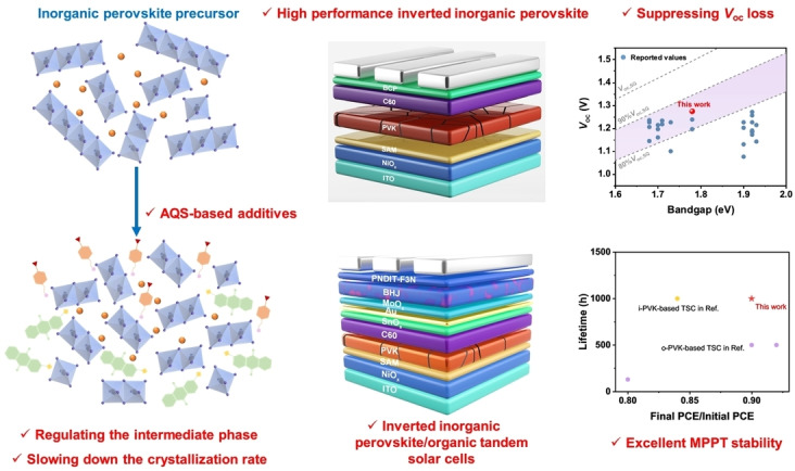
Two multifunctional additives of AQS : FPMA and AQS : FPEA are developed to suppress the voltage loss of inverted inorganic perovskite solar cells of 1.78 eV and construct highly efficient and durable inverted inorganic perovskite/organic tandem solar cells. The formation of AQS‐involved intermediate phase regulate the crystalliztaion rate resulting in lower defects of inorganic perovskites. Moreover, the benchmark of T 90 lifetime of perovskite/organic tandem solar cells under MPPT can be promoted to 1000 h, which will facilitate the real‐world deployment.
1. Introduction
The development of perovskite/organic tandem solar cell (P/O TSC) is promising way to surpass the Shockley–Queisser (S–Q) limit[ 1 , 2 ] and reduce the levelized cost of electricity (LCOE).[ 3 , 4 ] Over the past few years, there is a dynamic development in P/O TSC fueled by the emergence of narrow band gap (NBG) Y‐derivative acceptors for organic solar cells (OSCs).[ 5 , 6 , 7 , 8 ] Currently, a record power conversion efficiency (PCE) of 25.82 % [9] has been achieved in inverted P/O TSCs based on combining with a wide‐band gap (WBG) organic–inorganic hybrid perovskite subcell. However, the stability of these tandem cells is still not optimal, especially under the continuous operation conditions.[ 10 , 11 ] The long‐term stability of inverted P/O TSCs lag behind that of single‐junction normal band gap perovskite devices,[ 7 , 12 , 13 , 14 , 15 ] primarily due to the photo‐induced halide segregation in WBG hybrid perovskites front subcell. [16]
One way to improve the stability of tandem cells is to employ WBG all‐inorganic perovskites that have been shown to have superior stability under light illumination and thermal stress. [17] However, the poor film quality and large energy loss caused by the rapid crystallization[ 18 , 19 , 20 , 21 ] and mismatched energy levels [14] of these inorganic perovskites strongly hinder the realization of high‐performance all‐inorganic perovskite solar cells (PSCs). Recently, Li et al. [14] and Xu et al. [22] used dipole molecules and crosslinked (3‐mercaptopropyl) trimethoxysilane (MPTS) as interfacial modifiers to regulate the surface energy level of the perovskite, improving the open‐circuit voltage (V oc) of its derived device to ~1.22 V. Nevertheless, these values are much lower than those obtained from the organic–inorganic hybrid perovskites (V oc>1.3 V) with similar band gaps[ 8 , 23 , 24 ] due to high defect density in these WBG perovskites. [25] Additionally, the WBG all‐inorganic perovskites also suffer from halide segregation under continuous illumination. [26] Therefore, it is critical to develop an effective way to regulate the crystallization of all‐inorganic perovskites and optimize their energy alignment and phase stability simultaneously.
In this study, we have developed two multifunctional organic additives based on 9,10‐anthraquinone‐2‐sulfonic acid (AQS). [8] The AQ has been widely used as redox mediator due to its stable redox process, fast kinetics and synthetic tunability.[ 27 , 28 , 29 ] The sulfonic group on AQ scaffold can further tune the redox potential of AQ unit and interact with PbI2 to form an intermediate phase to regulate the crystallization process. The in situ characterizations verified the role of AQS in prolonging the intermediate‐phase stage thereby slow down the crystallization rate. Meanwhile, the AQS possesses a suitable redox potential of −0.21 V versus normal hydrogen electrode (NHE) between Pb (−0.365 V versus NHE) and I2 (0.536 V versus NHE), [8] therefore, it can act as a redox mediator to simultaneously reduce iodine and oxidize the metallic lead for suppressing halide segregation for enhancing phase stability. Different dipole moments on the energy alignment were also investigated by introducing 4‐(trifluoromethyl)benzylammonium (FPMA) and 4‐(trifluoromethyl)benzyl‐ ethylammonium (FPEA) as the counter cation for AQS, respectively. These cations not only possess impressive defect passivation capability, but also enable the device with desirable energy alignment. As a result, the single‐junction all‐inorganic PSCs could obtain a high PCE of 18.23 % with a high V oc approaching 1.3 V, which is among the highest for inverted all‐inorganic PSCs with the E g of 1.78 eV. Moreover, inverted P/O TSCs were fabricated by integrating this WBG PSC with an organic rear subcell to show an efficiency of over 23 %. Importantly, the P/O TSC with AQS : FPEA exhibited notable long‐term stability with a T 90 lifetime of 1000 h under maximum‐power‐point tracking (MPPT), which is very encouraging for the development for more robust P/O TSCs.
Results and Discussions
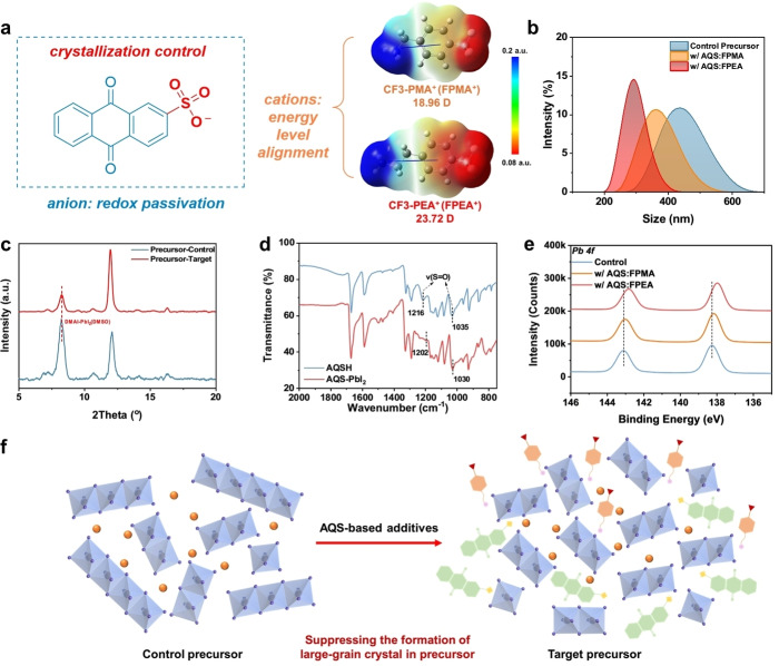
Two multifunctional molecules, i.e., AQS : FPMA and AQS : FPEA, were synthesized through a neutralization reaction, as shown in Scheme S1 (Supporting Information, SI). The chemical structures of the molecules are displayed in Figure 1 and their nuclear magnetic resonance (NMR) data are presented in Figures S1–S6 (SI). In the design of these two multifunctional additives, the AQS unit with the sulfonic acid functionalized quinoid unit could interact with Pb2+ and suppress the phase segregation via redox shuttle. [8] Furthermore, by selecting two organic cations with large dipole moments (18.96 D for FPMA and 23.72 D for FPEA), these additives could also tune the surface energy level. To examine the thermal stability of these additives, thermogravimetric analysis (TGA) and differential scanning calorimetry (DSC) were performed. As shown in Figure S7 (SI), the AQS : FPMA and AQS : FPEA only show weight loss at 272 °C and 289 °C, respectively. Meanwhile, no thermal transitions could be observed in the DSC thermograms, suggesting their excellent thermal stability.
Figure 1.
(a) The chemical structure of AQS−. DFT‐calculated electrostatic potential and dipole moment of CF3‐PMA+ (FPMA+) and CF3‐PEA+ (FPEA+). (b) The DLS diagrams of inorganic perovskite without additive and with AQS : FPMA and AQS : FPEA. (c) The XRD plots of the control precursor film without additive and target film with AQS : FPEA. (d) The FTIR spectra of bare AQS and AQS : PbI2. (e) High‐resolution Pb 4 f XPS plots of the annealed control perovskite film and perovskite films with AQS‐based additives. (f) Diagrams of our hypothesis that AQS‐group can regulate the formation of intermediate phases.
These molecules were then introduced into all‐inorganic WBG perovskite CsPb(IxBr1‐x)3 precursors as additives to study their effect on colloidal particles[ 30 , 31 ] in solution phase. The dynamic light scattering (DLS) diagram in Figure 1b shows that the particle size decreases with the introduction of AQS : FPMA and AQS : FPEA. It indicates that the additives could interact with perovskite components to suppress the formation of original intermediate phase to further slow down the crystallization rate [32] and contribute to the formation of high‐crystallinity perovskite films. To verify this, X‐ray diffraction (XRD) characterization was first conducted on perovskite films without thermal annealing, as shown in Figure 1c. The control perovskite film (without any additive) exhibits a strong diffraction peak corresponding to the intermediate phase of DMAI‐PbI2‐DMSO. [33] However, in the target perovskite film (with AQS : FPEA), the formation of DMAI‐PbI2‐DMSO intermediate phase is significantly suppressed with the appearance of a new diffraction peak at a higher 2θ position. This indicates the introduction of AQS‐based additives led to the formation of a new intermediate phase more thermodynamic favorable than DMAI‐PbI2‐DMSO.
To study which functional groups in AQS involved in the formation of the intermediate phase, the AQS‐PbI2 powder was prepared and characterized by Fourier‐transform infrared spectroscopy (FTIR). As shown in Figure 1d, the vibration mode from the S=O of the sulfonic acid on AQS shifted toward the low wavenumber, suggesting the strong interaction between PbI2 and AQS (Figure 1e). Therefore, we anticipated that the SO3 − in AQS could participate in the formation of a new intermediate phase, possibly DMAI‐PbI2‐AQS (DMSO), to compete with the original intermediate phase, thus reducing the colloidal particle size of the aggregates in precursor and regulating the crystallization of inorganic perovskite (Figure 1f).
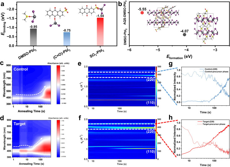
Our density functional theory (DFT) calculations provided the theoretical evidence for forming a new intermediate phase. As illustrated in Figure 2a, the binding energies (E bindings) of DMSO‐PbI2, C=O<C‐PbI2, and SO3‐PbI2 are −0.95, −0.75, and −1.54 eV, respectively. The largest absolute E binding of SO3‐PbI2 indicates that the ‐SO3 group of AQS is most likely to participate in the formation of a new intermediate phase. The formation energies (E formations) of various possible intermediate phases were calculated, with values of −4.07 and −5.55 eV for DMSO‐PbI2 and AQS‐DMSO‐PbI2, respectively. This result illustrates that the AQS‐involved intermediate phase with the lower E formation is more thermodynamically favored to form in the precursor, agreeing well with the XRD patterns of the wet perovskite films. The new intermediate phase would potentially modulate the crystallization to optimize the film quality of the resultant perovskite. [34]
Figure 2.
(a) The calculated binding energis (E bindings) of DMSO‐PbI2, C=O (AQS)‐PbI2 and SO3 (AQS)‐PbI2. (b) The calculated formation energies (E formations) of DMSO‐PbI2 and AQS‐DMSO‐PbI2. The inserts of Figures (a) and (b) are the optimized molecular and crystal structure. The in situ absorption spectra of the annealing process of control perovskite film without additive (c) and target perovskite film with AQS : FPEA (d). The in situ GIWAXS patterns of the annealing process of control perovskite film without additive (e) and target perovskite film with AQS : FPEA (f). The line‐cut profiles correspond to the formation of the γ phase and the disappearance of the δ phase in the control film without additive (g) and the target film with AQS : FPEA (h).
Next, in situ characterizations of perovskite films were performed to reveal the effect of the AQS‐involved intermediate phase on the crystallization of WBG all‐inorganic perovskite during annealing. Considering that AQS : FPEA played a more significant role in reducing the particle size of the precursor solution, we selected the AQS : FPEA‐containing film as the target film in the in situ characterizations. As shown in Figure 2c, the width of the absorption peak of the control film decreases in the first 5 s attributed to the solvent volatilization. No significant change can be observed within 100 s. After 100 s, a fast broadening of absorption peak indicates the rapid crystallization process in forming the perovskite phase in the control film. In contrast, the absorption peak of the target film, as recorded in Figure 2d, shows a gradient change pattern. The presence of a step with strong absorption at the preliminary annealing stage is associated with the formation of AQS‐DMSO‐PbI2 intermediate phase. Subsequently, a slowdown crystallization process illustrates that the AQS‐based additive can participate in regulating the crystallization of all‐inorganic perovskites. Our in situ grazing incident wide‐angle X‐ray scattering (GIWAXS) characterizations further provided direct information on the crystallization process. Figures 2e–f are the 2D mappings displaying variations of diffraction peaks along the q z direction depending on the annealing time. The stronger (110) and (220) diffraction peaks [35] in the target film after annealing (Figure 2f and Figure S8, SI) implying that the AQS‐based additives facilitate the formation of photo‐active γ phase. [36] As the phase transition during annealing can be clearly distinguished at q z around 2 Å−1, the line‐cut profiles were further extracted corresponding to (220) peaks of control and target films. A clear plateau with strong diffraction intensity and a subsequent slow‐down crystallization process can also be observed (Figures 2g–h), which is highly consistent with their in situ absorption profiles (Figure 2d). These results synergistically verified our hypothesis that the AQS‐based additives can lead to the formation of a new intermediate phase to regulate the crystallization for achieving better crystallinity.
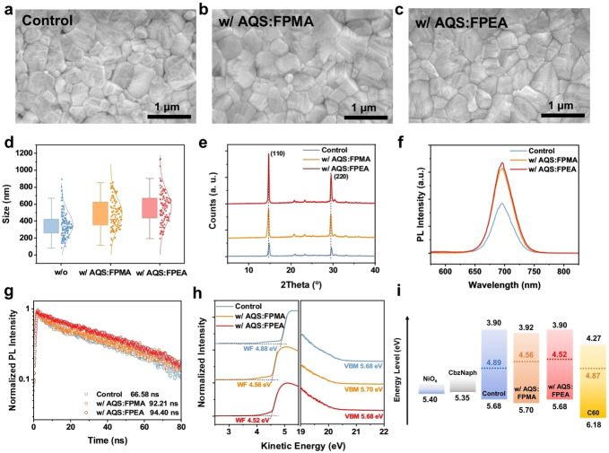
Considering the unique effect of AQS‐based additives on regulating the crystallization of all‐inorganic perovskites, the film quality of the perovskite with and without the additives were further investigated in detail. The top‐viewing scanning electronic microscopy (SEM) was first used to characterize the morphology of the all‐inorganic perovskite films. As displayed in Figures 3a–d, the grain sizes of the perovskites with either AQS : FPMA or AQS : FPEA are enlarged with respect to the control sample, probably resulting from the slowed crystallization mediated by the AQS‐involved intermediate phase. Their crystal structures were also studied by XRD, as provided in Figure 3e. It reveals that the favorable γ phase dominates after thermal annealing, while the films with AQS‐based additives exhibited stronger (110) diffraction peaks, showing better crystallinity of the target perovskite samples. Therefore, we anticipate the non‐radiative recombination could be suppressed in the target perovskites due to improved film quality. To prove this, steady‐state photoluminescence (PL) and time‐resolved photoluminescence (TRPL) were used to study the recombination and carrier dynamics within perovskites (Figure 3f–g). All samples show similar PL peaks at ~698 nm corresponding to the band gap of 1.78 eV. Compared with the control perovskite, a stronger PL intensity was observed in the perovskites with AQS‐based additives, indicating suppressed non‐radiative recombination. These results agree well with the prolonged carrier lifetime of the perovskite after modifications, where the average carrier lifetimes were calculated to be 66.58 ns, 92.21 ns, and 94.40 ns for control, perovskite with AQS : PMEA, and with AQS : FPEA, respectively.
Figure 3.
The SEM patterns of the control perovskite film (a), the AQS : FPMA‐based film (b) and the AQS : FPEA‐based film (c). (d) The statistic of grain sizes corresponding to Figures 3a–c. (e) The XRD plots of perovskite films with or without additives. The PL spectra (f) and TRPL spectra (g) of different perovskite films. (h) The UPS spectra of the control perovskite film and films with additives. (i) The energy level diagram of perovskites corresponds to the UPS spectra.
The electronic structure of the films was investigated by ultraviolet photoelectron spectroscopy (UPS) to examine the energy levels of perovskites with and without additives. As shown in Figures 3h–i, the work functions (WFs) of perovskite surface decrease from 4.89 eV to 4.56 eV and 4.52 eV after introducing AQS : FPMA and AQS : FPEA into perovskite, respectively. The WF shifts by 0.33–3.37 eV towards vacuum level indicates that the modified perovskites become more n‐type, which can be attributed to the dipolar cations [14] of AQS. The more n‐type surface can facilitate more efficient charge transfer at the interface, resulting in lower interfacial recombination loss.
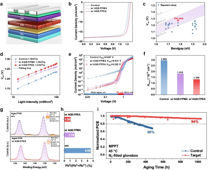
To study the impact of multifunctional additives on device performance, inverted inorganic WBG PSCs were fabricated with the device structure shown in Figure 4a. As displayed in Figures 4b–c and Figure S9 (SI), the devices based on AQS‐based additives show increased photovoltage performance with a remarkable V oc of 1.29 V can be achieved for AQS : FPEA‐based device, representing the highest V oc value among the inverted all‐inorganic PSCs with ~1.78 eV band gap. In addition, as shown in Figure S10 and Table S1 (SI), the current density‐voltage (J–V) characteristics of PSCs with AQS‐based additives exhibit suppressed hysteresis compared to that of the control cell. Meanwhile, due to the improved film quality, higher External Quantum Efficiency (EQE) responses of devices with AQS‐based additives can also be found in Figure S11 (SI), affording an increased 0.46 mA cm−2 in the integrated short‐circuit current density (J sc) from EQE. Moreover, the target device with AQS‐FPEA also exhibited a higher stabilized power output (SPO) than the control PSC (Figure S12, SI).
Figure 4.
(a) The device architecture of the inverted inorganic PSC. (b) J–V characteristics of the control PSC, and PSCs with AQS : FPMA and AQS : FPEA. (c) The statistics of V oc of inverted inorganic PSCs in this work and corresponding literature. (d) The light‐intensity dependent curves of V oc of the control device, and devices with AQS : FPMA and AQS : FPEA. The dark‐current curves (e) and the trap‐state density (f) of the control device, and devices with AQS : FPMA and AQS : FPEA. (g) The Pb 4 f high‐resolution XPS spectra of the aged perovskite without additive and with AQS : FPEA. (h) The Pb0 ratio of aged perovskites without additive, and with AQS : FPMA and AQS : FPEA. (i) The MPPT stability of the control device without additive and the target device with AQS : FPEA.
Then, the ideal factors of perovskite devices were examined by performing the light‐intensity dependent V oc. As exhibited in Figure 4d, the lower ideal factors are obtained in devices based on AQS‐based additives, indicating suppressed trap‐assisted recombination in devices. Meanwhile, the electrochemical impedance spectroscopy (EIS) measurements were performed to study the carrier‐recombination process. [37] As exhibited in Nyquist plots (Figure S13, SI), the larger recombination resistances (R recs) of the devices based on AQS : FPMA (2178 Ω) and AQS : FPEA (2231 Ω) than that of the control device (1269 Ω) reveal the suppressed carrier recombination process[ 32 , 38 ] in devices with AQS‐based additives, which implies the lower trap densities in the devices.
Further, space‐charge‐limited‐current (SCLC) method was used to quantify the trap densities (N traps) of different devices (Figure 4e), the trap‐filled limit voltage (V TFL) of the control device is 0.867 V, while that of AQS : FPMA and AQS : FPEA‐based devices is 0.531 V and 0.392 V, respectively, indicating lower trap density [39] in the devices with AQS‐containing additives. The N traps were calculated based on the following equation: [40]
| (1) |
where ϵ represents the dielectric constant, q is the elementary electric charge, and L is the film thickness. As summarized in Figure 4f and Table 1, the N traps of perovskite devices were reduced from 2.964×1016 cm−3 of the control device to 1.816×1016 cm−3 (w/ AQS : FPMA) and 1.340×1016 cm−3 (w/AQS : FPEA). These results suggest that AQS‐based additives can significantly reduce the recombination loss in PSCs, which could be ascribed to their better film quality, desirable dipole moment and defect passivation effect. Moreover, thermal admittance spectroscopy (TAS) [41] was performed to study the effect of AQS‐based additives on the energetic distribution of defects in perovskites. As exhibited in Figure S14 (SI), the introduction of AQS : FPEA not only can modulate the energy level of defects but also reduce the total trap state density with 7.62 1016 and 1.26 1017 cm−3 for the devices with and without AQS : FPEA, respectively. This can be attributed to its impact on regulating crystallization and defect passivation,[ 42 , 43 ] which suppress the recombination loss and ion migration [43] in perovskites to result in high V oc and enhanced stability of the devices.
Table 1.
The statistics of photovoltaic parameters of single‐junction PSCs.
|
Additive |
V oc (V) |
J sc (mA/cm2) |
FF (%) |
PCE (%) |
N trap (*1016 cm−3) |
|---|---|---|---|---|---|
|
w/o |
1.24 (1.234±0.005) |
17.80 (17.70±0.10) |
77.18 (77.04±0.71) |
17.04 (16.83±0.21) |
2.964 |
|
w/AQS : FPMA |
1.27 (1.262±0.008) |
17.83 (17.93±0.12) |
79.38 (78.53±0.65) |
17.97 (17.77±0.20) |
1.816 |
|
w/AQS : FPEA |
1.29 (1.286±0.005) |
18.07 (18.07±0.10) |
79.74 (79.24±0.67) |
18.59 (18.39±0.13) |
1.340 |
Then, the effects of additives on the phase stability and device durability of inorganic perovskites were further investigated. X‐ray photoelectron spectroscopy (XPS) was used to investigate if AQS‐based additives could reduce the formation of Pb0 caused by the reduction of Pb2+ in the mixed‐halide systems. To mimic device aging, perovskite films were exposed to continuous irradiation at an intensity equal to 1 sun for 24 h. After aging, as exhibited in Figure 4g, a significant metallic Pb 4 f signal could be detected in the XPS spectra of aged control films, while those of aged perovskites with AQS‐based additives showed negligible signals. The ratios of Pb0 to total Pb elements were also calculated in different aged perovskites. As summarized in Figure 4h, the ratio can be reduced from 4.59 % in the aged control perovskite to 1.75 % in the aged w/ AQS : FPMA perovskite (Figure S15, SI) and 1.06 % in the aged w/ AQS : FPEA perovskite. Meantime, the introduction of AQS‐based additives also result in more stable I/Pb ratio in inorganic perovskite as shown in Figure S16 (SI), suggesting the emergence of oxidative product I0 is suppressed. The PL spectroscopy was further performed to investigate the effect of AQS‐based additives on halide segregation in perovskites. As exhibited in Figure S17 (SI), the stable PL spectra of the perovskite films with AQS‐based additives illustrate the capability of AQS on suppressing the halide segregation issue. These results demonstrate that AQS can induce an impressive redox‐shuttle effect [8] on enhancing the phase stability of the mixed‐halide perovskite and the stability of the derived devices. Moreover, due to the hydrophobic trifluoromethyl (−CF3) group of organic cations, the perovskite films with AQS‐based additives also exhibit enhanced hydrophobicity (Figure S18, SI), contributing to the better device stability under ambient atmosphere. As expected, the device based on AQS : FPEA can maintain 94 % of the initial PCE after MPP tracking for 1000 h, while the efficiency of the control device decreased 32 % after 470 h (Figure 4i). This result further reveals the unique impact of AQS‐containing additives in enhancing the durability of WBG inorganic perovskites, which is crucial for their future deployment.
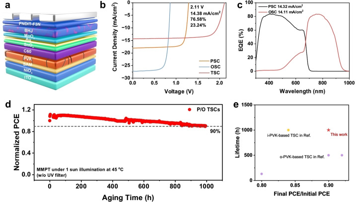
Considering the impressive device performance of the all‐inorganic WBG PSCs, we further explored their applications in P/O TSCs. The inverted P/O TSCs based on AQS : FPEA were constructed with an architecture depicted in Figure 5a. The PM6 : BTP‐eC9 : PC71BM active layer was selected to integrate with the optimal AQS : FPEA‐based inorganic perovskite to fabricate the inverted P/O TSC. The resultant TSC exhibits a high PCE of 23.24 % (Figure 5b) with a V oc of 2.11 V, a J sc of 14.38 mA/cm2 (14.11 mA/cm2 integrated by EQE in Figure 5c), and a fill factor (FF) of 76.58 %. This is the highest PCE among inverted P/O TSCs based on all‐inorganic perovskite as a sub‐cell (Figure S19, SI). Besides, the durable efficiency during the SPO tracking (Figure S20, SI) indicates that the AQS‐based inorganic PSC has great potential to be used in constructing highly durable TSCs. More importantly, a T 90 lifetime of 1000 h (Figure 5d) under MPPT can be achieved, which is also among the best device lifetime reported so far for P/O TSCs.
Figure 5.
(a) The architecture of P/O TSC based on inorganic perovskite. (b) J–V characteristics of the P/O TSC, single‐junction PSC and single‐junction OSC. (c) EQE curves of P/O TSCs. The star dot represents the PCE achieved in this work. (d) The PCE evaluation of P/O TSCs based on inorganic perovskite with AQS : FPEA. (e) The statistics of lifetime development of P/O TSCs.
Conclusion
Two novel multifunctional additives, AQS : FPMA and AQS : FPEA, have been designed and synthesized. The AQS unit plays a critical role in forming a new intermediate phase, leading to high‐quality all‐inorganic perovskites with reduced defect density through regulated crystallization. Moreover, the efficient redox shuttling in AQS also enhances the phase stability of these WBG perovskites, therefore, contributes to the improved stability of derived devices. The integration of AQS with organic dipolar molecules, FPMA and FPEA, further enables effective passivation of Pb2+ and adjustment of surface energy level. As a result, a high PCE over 18 % and a record V oc~1.3 V could be achieved in a single‐junction all‐inorganic PSC with superior long‐term stability under the MPPT condition. More importantly, the WBG inorganic perovskite could be used as the front subcell in constructing an inverted P/O TSC to achieve a very encouraging T 90 lifetime of 1000 h under MPPT, surpassing most reported lifetime for P/O TSCs.
Supporting Information
Supporting Information is available from the Wiley Online Library or from the author.
Conflict of Interests
The authors declare no conflict of interest.
2.
Supporting information
As a service to our authors and readers, this journal provides supporting information supplied by the authors. Such materials are peer reviewed and may be re‐organized for online delivery, but are not copy‐edited or typeset. Technical support issues arising from supporting information (other than missing files) should be addressed to the authors.
Supporting Information
Acknowledgments
A.K.Y.J. thanks the sponsorship of the Lee Shau‐Kee Chair Professor (Materials Science), and the support from the APRC Grants (9380086, 9610508, 9610419, 9610492) of the City University of Hong Kong, the TCFS Grant (GHP/018/20SZ) and MRP Grant (MRP/040/21X) from the Innovation and Technology Commission of Hong Kong, the Green Tech Fund (202020164) from the Environment and Ecology Bureau of Hong Kong, the GRF grants (11307621, 11316422) from the Research Grants Council of Hong Kong, Shenzhen Science and Technology Program (SGDX20201103095412040), Guangdong Major Project of Basic and Applied Basic Research (2019B030302007). J.Y. acknowledges funding support from Hong Kong Polytechnic University (Grant no. P0042930) and a grant from the Research Grants Council of the Hong Kong Special Administrative Region, China (Project No. PolyU 25300823).
Li Y., Yan Y., Fu Y., Jiang W., Liu M., Chen M., Huang X., Lu G., Lu X., Yin J., Wu S., Jen A. K.-Y., Angew. Chem. Int. Ed. 2024, 63, e202412515. 10.1002/anie.202412515
Contributor Information
Jun Yin, Email: jun.yin@polyu.edu.hk.
Shengfan Wu, Email: shengfanwu@ln.edu.hk.
Alex K.‐Y. Jen, Email: alexjen@cityu.edu.hk.
Data Availability Statement
The data that support the findings of this study are available from the corresponding author upon reasonable request.
References
- 1. Vos A. D., J. Phys. D 1980, 13, 839. [Google Scholar]
- 2. Eperon G. E., Hörantner M. T., Snaith H. J., Nat. Chem. Rev. 2017, 1, 0095. [Google Scholar]
- 3. Brinkmann K. O., Wang P., Lang F., Li W., Guo X., Zimmermann F., Olthof S., Neher D., Hou Y., Stolterfoht M., Wang T., Djurišić A. B., Riedl T., Nat. Rev. Mater. 2024, 9, 202. [Google Scholar]
- 4. Wu S., Liu M., Jen A. K.-Y., Joule 2023, 7, 484. [Google Scholar]
- 5. Yuan J., Zhang Y., Zhou L., Zhang G., Yip H.-L., Lau T.-K., Lu X., Zhu C., Peng H., Johnson P. A., Leclerc M., Cao Y., Ulanski J., Li Y., Zou Y., Joule 2019, 3, 1140. [Google Scholar]
- 6. Jiang K., Zhang J., Zhong C., Lin F. R., Qi F., Li Q., Peng Z., Kaminsky W., Jang S.-H., Yu J., Deng X., Hu H., Shen D., Gao F., Ade H., Xiao M., Zhang C., Jen A. K.-Y., Nat. Energy 2022, 7, 1076. [Google Scholar]
- 7. Li Y., Liu K.-K., Lin F. R., Jen A. K.-Y., Solar RRL 2023, 2300531. [Google Scholar]
- 8. Wu S., Yan Y., Yin J., Jiang K., Li F., Zeng Z., Tsang S.-W., Jen A. K.-Y., Nat. Energy 2024, 9, 411. [Google Scholar]
- 9. Zhang Z., Chen W., Jiang X., Cao J., Yang H., Chen H., Yang F., Shen Y., Yang H., Cheng Q., Chen X., Tang X., Kang S., Ou X., Brabec C. J., Li Y., Li Y., Nat. Energy 2024, DOI 10.1038/s41560-024-01491-0. [DOI] [Google Scholar]
- 10. Wu X., Liu Y., Qi F., Lin F., Fu H., Jiang K., Wu S., Bi L., Wang D., Xu F., Jen A. K.-Y., Zhu Z., J. Mater. Chem. A 2021, 9, 19778. [Google Scholar]
- 11. Mali S. S., Patil J. V., Steele J. A., Nazeeruddin M. K., Kim J. H., Hong C. K., Energy Environ. Sci. 2024, 17, 1046. [Google Scholar]
- 12. Qi F., Li Y., Zhang R., Lin F. R., Liu K., Fan Q., Jen A. K.-Y., Angew. Chem. Int. Ed. 2023, 62, e202303066. [DOI] [PubMed] [Google Scholar]
- 13. Li Y., Huang B., Zhang X., Ding J., Zhang Y., Xiao L., Wang B., Cheng Q., Huang G., Zhang H., Yang Y., Qi X., Zheng Q., Zhang Y., Qiu X., Liang M., Zhou H., Nat. Commun. 2023, 14, 1241. [DOI] [PMC free article] [PubMed] [Google Scholar]
- 14. Li T., Xu J., Lin R., Teale S., Li H., Liu Z., Duan C., Zhao Q., Xiao K., Wu P., Chen B., Jiang S., Xiong S., Luo H., Wan S., Li L., Bao Q., Tian Y., Gao X., Xie J., Sargent E. H., Tan H., Nat. Energy 2023, 610. [Google Scholar]
- 15. Zhu H., Teale S., Lintangpradipto M. N., Mahesh S., Chen B., McGehee M. D., Sargent E. H., Bakr O. M., Nat. Rev. Mater. 2023, 569. [Google Scholar]
- 16. Shen X., Gallant B. M., Holzhey P., Smith J. A., Elmestekawy K. A., Yuan Z., Rathnayake P. V. G. M., Bernardi S., Dasgupta A., Kasparavicius E., Malinauskas T., Caprioglio P., Shargaieva O., Lin Y., McCarthy M. M., Unger E., Getautis V., Widmer-Cooper A., Herz L. M., Snaith H. J., Adv. Mater. 2023, 35, 2211742. [DOI] [PubMed] [Google Scholar]
- 17. Wang J., Zhang J., Zhou Y., Liu H., Xue Q., Li X., Chueh C.-C., Yip H.-L., Zhu Z., Jen A. K. Y., Nat. Commun. 2020, 11, 177. [DOI] [PMC free article] [PubMed] [Google Scholar]
- 18. Chen W., Li X., Li Y., Li Y., Energy Environ. Sci. 2020, 13, 1971. [Google Scholar]
- 19. Ma J., Qin M., Li P., Han L., Zhang Y., Song Y., Energy Environ. Sci. 2022, 15, 413. [Google Scholar]
- 20. Sun N., Fu S., Li Y., Chen L., Chung J., Saeed M. M., Dolia K., Rahimi A., Li C., Song Z., Yan Y., Adv. Funct. Mater. 2023, 2309894. [Google Scholar]
- 21. Yin G., Zhao H., Jiang H., Yuan S., Niu T., Zhao K., Liu Z., (Frank) Liu S., Adv. Funct. Mater. 2018, 28, 1803269. [Google Scholar]
- 22. Xu T., Xiang W., Ru X., Wang Z., Liu Y., Li N., Xu H., Liu S., Adv. Mater. 2024, 2312237. [DOI] [PubMed] [Google Scholar]
- 23. An Y., Zhang N., Zeng Z., Cai Y., Jiang W., Qi F., Ke L., Lin F. R., Tsang S., Shi T., Jen A. K., Yip H., Adv. Mater. 2023, 2306568. [DOI] [PubMed] [Google Scholar]
- 24. Wang X., Zhang D., Liu B., Wu X., Jiang X., Zhang S., Wang Y., Gao D., Wang L., Wang H., Huang Z., Xie X., Chen T., Xiao Z., He Q., Xiao S., Zhu Z., Yang S., Adv. Mater. 2023, 2305946. [DOI] [PubMed] [Google Scholar]
- 25. Shen C., Ye T., Yang P., Chen G., Adv. Mater. 2024, 2401498. [DOI] [PubMed] [Google Scholar]
- 26. Frolova L. A., Luchkin S. Y., Lekina Y., Gutsev L. G., Tsarev S. A., Zhidkov I. S., Kurmaev E. Z., Shen Z. X., Stevenson K. J., Aldoshin S. M., Troshin P. A., Adv. Energy Mater. 2021, 11, 2002934. [Google Scholar]
- 27. Mourad E., Coustan L., Lannelongue P., Zigah D., Mehdi A., Vioux A., Freunberger S. A., Favier F., Fontaine O., Nat. Mater. 2017, 16, 446. [DOI] [PubMed] [Google Scholar]
- 28. Cai C.-Y., Lai X.-L., Wang Y., Hu H.-H., Song J., Yang Y., Wang C., Xu H.-C., Nat. Catal. 2022, 5, 943. [Google Scholar]
- 29. Lin K., Chen Q., Gerhardt M. R., Tong L., Kim S. B., Eisenach L., Valle A. W., Hardee D., Gordon R. G., Aziz M. J., Marshak M. P., Science 2015, 349, 1529. [DOI] [PubMed] [Google Scholar]
- 30. Kim J., Park B., Baek J., Yun J. S., Kwon H.-W., Seidel J., Min H., Coelho S., Lim S., Huang S., Gaus K., Green M. A., Shin T. J., Ho-baillie A. W. Y., Kim M. G., Seok S. I., J. Am. Chem. Soc. 2020, 142, 6251. [DOI] [PubMed] [Google Scholar]
- 31. Jung M., Ji S.-G., Kim G., Seok S. I., Chem. Soc. Rev. 2019, 48, 2011. [DOI] [PubMed] [Google Scholar]
- 32. Ge J., Chen R., Ma Y., Wang Y., Hu Y., Zhang L., Li F., Ma X., Tsang S., You J., Jen A. K. Y., Liu S. F., Angew. Chem. Int. Ed. 2024, 63, e202319282. [DOI] [PubMed] [Google Scholar]
- 33. Wang H., Liu H., Dong Z., Wei X., Li W., Zhu L., Zhu C., Bai Y., Chen H., Sci. Bull. 2023, 68, 192. [DOI] [PubMed] [Google Scholar]
- 34. Li F., Deng X., Shi Z., Wu S., Zeng Z., Wang D., Li Y., Qi F., Zhang Z., Yang Z., Jang S.-H., Lin F. R., Tsang S., Chen X.-K., Jen A. K.-Y., Nat. Photonics 2023. [Google Scholar]
- 35. Wu X., Wang S., Zhang J., Shiu H.-W., Hsu Y.-J., Yan H., Zhu J., Lu X., Nano Energy 2023, 117, 108907. [Google Scholar]
- 36. Chen Y., Liu X., Zhao Y., Angew. Chem. Int. Ed. 2022, 61, e202110603. [DOI] [PubMed] [Google Scholar]
- 37. Guerrero A., Bisquert J., Garcia-Belmonte G., Chem. Rev. 2021, 121, 14430. [DOI] [PubMed] [Google Scholar]
- 38. Gu X., Xiang W., Tian Q., (Frank) Liu S., Angew. Chem. Int. Ed. 2021, 60, 23164. [DOI] [PubMed] [Google Scholar]
- 39. Liu M., Bi L., Jiang W., Zeng Z., Tsang S., Lin F. R., Jen A. K.-Y., Adv. Mater. 2023, 2304415. [DOI] [PubMed] [Google Scholar]
- 40. Shi D., Adinolfi V., Comin R., Yuan M., Alarousu E., Buin A., Chen Y., Hoogland S., Rothenberger A., Katsiev K., Losovyj Y., Zhang X., Dowben P. A., Mohammed O. F., Sargent E. H., Bakr O. M., Science 2015, 347, 519. [DOI] [PubMed] [Google Scholar]
- 41. Shao Y., Xiao Z., Bi C., Yuan Y., Huang J., Nat. Commun. 2014, 5, 5784. [DOI] [PubMed] [Google Scholar]
- 42. Huang G., Chen J., Wang B., Cheng Q., Li Y., Zafar S. U., Yue T., Yan Y., Du W., Zhang H., Liu X., Zhang Y., Zhou H., Nano Lett. 2022, 22, 7545. [DOI] [PubMed] [Google Scholar]
- 43. Chen B., Rudd P. N., Yang S., Yuan Y., Huang J., Chem. Soc. Rev. 2019, 48, 3842. [DOI] [PubMed] [Google Scholar]
Associated Data
This section collects any data citations, data availability statements, or supplementary materials included in this article.
Supplementary Materials
As a service to our authors and readers, this journal provides supporting information supplied by the authors. Such materials are peer reviewed and may be re‐organized for online delivery, but are not copy‐edited or typeset. Technical support issues arising from supporting information (other than missing files) should be addressed to the authors.
Supporting Information
Data Availability Statement
The data that support the findings of this study are available from the corresponding author upon reasonable request.


