Abstract
Objective
Calcaneal fracture fixation remains a challenging procedure in orthopedics, with computational tools increasingly aiding in the optimization of preoperative planning. To compare the biomechanical stability of intramedullary fixation and locking plate fixation for Sanders II and III calcaneal fractures by three-dimensional (3D) finite element analysis and to provide a theoretical basis for clinical application.
Methods
The Computed Tomography (CT) images were segmented using Mimics software (Materialise NV, Belgium) to identify the region of interest based on threshold segmentation. The 3D morphology was reconstructed using Mimics 10.01 software. Subsequently, Geomagic2012 software (3D Systems, USA) was employed to remove noise points, sharp corners, and scattered points, achieving a smooth surface map. This map was saved in Initial Graphics Exchange Specification (IGES) format and imported into Solidworks (Dassault Systèmes, France) for model assembly and volume model construction. A three-dimensional finite element model of Sanders II/III, calcaneal fractures with intramedullary fixation and locking plate fixation, was established and analyzed by linear finite element analysis. The forced displacement, stiffness, and stress distribution of the two fixation methods were calculated. In addition, the three-dimensional model was tested using a compression mechanical experiment.
Results
Comparing fixation methods for Sander II and III fractures, the force-displacement curve of the intramedullary nail group aligned more closely with standards. Under axial compression, bone stress was highest with the Sanders II locking plate and lowest with the intramedullary nail. Across models, the intramedullary nail consistently exhibited slightly higher stress than the locking plate. The intramedullary nailing group model of the overall stiffness was slightly greater than the locking plate. By comparing the compressive mechanical test performance of the two fixation methods, it was found that the plate fixation group had an abnormal load until 7092.895 N, which was 1.5 times more than the load of the intramedullary nail.
Conclusion
Both intramedullary fixation and locking plate fixation for Sanders II and III calcaneal fractures have certain biomechanical stability, and locking plate fixation has potential application value in clinical practice.
Keywords: Calcaneus, Fractures, Finite element analysis, Intramedullary fixation, Locking plate fixation
Introduction
Calcaneal fractures mainly occur in young people between 20 and 40 years old, accounting for 60% of all tarsal fractures. Most of the fractures are caused by vertical and vertical violence [1]. Open reduction and fixation are often used for calcaneal fractures involving the articular surface with obvious displacement. The traditional lateral “L” shaped expanded incision approach is the “gold standard” for surgical treatment of calcaneal fractures [2], which can cope with almost all complex types of calcaneal fractures. During the operation, the calcaneal tuberosity, lateral wall, subtalar joint, and calcaneocuboid joint can be fully exposed so as to obtain satisfactory reduction and strong internal fixation. However, with a large number of studies and follow-up reports [3], it has been found that this traditional surgical approach has relatively high postoperative complications, including incision flap necrosis, infection, sural nerve injury, etc. In order to reduce wound complications and achieve effective reduction, especially the reduction of posterior articular surface, the transtarsal sinus incision approach has been recommended as a new surgical strategy [4]. In particular, minimally invasive limited open internal fixation for Sanders II and III calcaneal fractures has become a consensus among trauma orthopedic surgeons [5]. Although minimally invasive incision causes less damage to the surrounding soft tissue and greatly reduces the risk of flap necrosis and infection after operation, its fixation technique is not stable, which often leads to the instability of the medial column of the calcaneus. It is difficult to maintain the reduction of the fracture with calcaneal plate internal fixation. Therefore, patients with calcaneal fractures often suffer from fracture reduction loss and calcaneal varus after the operation.
Addressing the challenge of effective postoperative fixation, significant achievements have been made in the research of minimally invasive fixation of calcaneal fractures. Reinhardt et al. reported that the biomechanical study comparing minimally invasive intramedullary calcaneal nail and calcaneal locking plate in the treatment of intra-articular calcaneal fractures showed that the intramedullary calcaneal nail had a high degree of stability, with effectiveness comparable to the calcaneal locking nail plate. According to the research results, the intramedullary calcaneal nail could be selected for the treatment of intra-articular calcaneal fractures [6]. Fabrizio et al. showed that for SandersII and III calcaneal fractures, the minimally invasive intramedullary nail system of calcaneus has excellent effects on the maintenance and reduction of the subtalar articular surface and the calcaneal force line [7]. Anica et al. compared the efficacy of intramedullary nail and standard locking plates in the treatment of calcaneal fractures and found that intramedullary nail showed better postoperative efficacy and greatly reduced postoperative incision complications [8]. Recently, there have been corresponding reports on the application of calcaneal bone marrow nail in the treatment of displaced intra-articular calcaneal fractures abroad, which can obtain high stability and reduce soft tissue complications [9]. There is no report of the calcaneal intramedullary fixation system in China. Generally, it is considered in a narrow sense that the application of calcaneal intramedullary nail is limited in the scope of operation, cannot deal with severe comminuted calcaneal fractures, and lacks sufficient support for the important posterior articular surface.
Three-dimensional (3D) imaging technologies have transformed traumatology by enabling precise surgical planning and the optimization of fixation strategies. These advancements, notably in micro-Computed Tomography (CT) [10] and 3D [11] printing, facilitate accurate reconstructions and implant placements, significantly reducing surgical invasiveness and enhancing outcomes. Recent studies have demonstrated that intraoperative 3D imaging enhances spinal trauma surgery by adapting to vertebrae positioning changes and enabling precise implant placement with minimal radiation exposure [12, 13]. Additionally, 3D imaging has been crucial in restoring the subthalamic congruence in calcaneal fractures, offering precise guidance for realignment and ensuring optimal surgical outcomes. Surgeons utilize fractured 3D models to simulate reduction techniques and uninjured models to optimize plate selection, a practice that has yielded excellent results in treating clavicle, calcaneal, pilon, and ankle fractures [14–16]. However, despite these advancements, there remains a critical need for a more anatomically adapted and minimally invasive intramedullary calcaneal system.
Therefore, this study aims to design a minimally invasive calcaneal intramedullary system based on three-dimensional Computed Tomography (CT) image technology that is consistent with the anatomical morphology of Chinese people and to observe its effect on restoring and maintaining the anatomical structure of the calcaneus through biomechanical tests.
Materials and methods
Source of sample
A 36-year-old healthy volunteer weighting 70 kg was selected from Shanghai Pudong New Area Zhoupu Hospital. Foot and ankle injuries or diseases of volunteers were excluded by X-ray examination. CT scan was used to obtain the calcaneal data (in line with the statistics of Chinese calcaneal average parameters).
CT image processing
Volunteers underwent bilateral ankle spiral CT scan (PQ6000 Picker companies in the United States, 64-row dual-source spiral CT), set the parameters as follows: 120 kv voltage/current / 220 mA, 1 mm thick, pitch of 1.5, the data resolution was 944 ˟ 944. A single threshold was used to segment bone images from CT plain scan data. Each slice was preprocessed to extract calcaneal-related information, and then the 3D model of the calcaneus was reconstructed from these slice images. The data obtained were saved in Dicom format. In the Mimics software, mask extraction of interest groups were mainly used, followed by the calculation and 3D reconstruction of three-dimensional shapes of various organizations. This model can be used as the STL format output.
Surface construction
Geomagic software was used to construct the surface of CT scanning images. First, the STL format file obtained in the Mimics software was imported to improve the accuracy of the model, and the noise was used to remove the scattered surface and broken surface of the model. The model surface was preliminarily smoothed by removing sharp corners and rapid smoothing. After the software analysis of the curvature, the surface of the model is smooth enough to enter the shape stage to construct the surface. The NURBS surface is fitted by fine adjustments to the function surface, such as contour recognition, surface construction, and modification. Finally, we enter the Fashion stage by defining the surface feature types and fitting the quasi-CAD surface. The resulting models were surface models and saved in the universal IGES (.igs) format.
CAD model construction
The geometric solid model obtained from the above steps was imported into Hypermesh12 for mesh partitioning, boundary conditions imposition, material properties assignment, and contact definition. Finally, it was submitted to ABAQUS 6.12 for finite element analysis. The diagram was saved in IGES format and imported into Solidworks/UGS for model assembly and volume model construction. At the beginning of modeling, considering the attachment relationship between muscle and bone, all tissues were modeled using the edge partial extension. The Solidworks/UGS software was used for the Boolean operation to calculate the common binding surface of each tissue, and the volume model was constructed by automatically forming the volume model of the closed continuous surface.
Finite element model construction
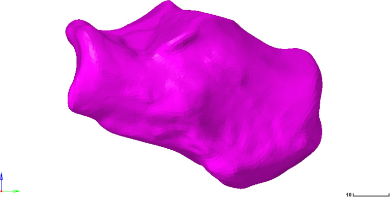
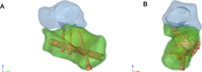
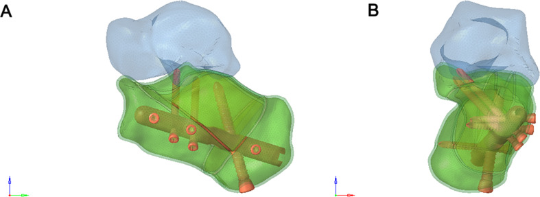
C3D6 was used to simulate calcaneal cortical bone, and C3D4 was used to simulate cancellous bone and subsequent implants. According to the similarity degree of the elements for the geometric shape fitting, the final basic dimension of the bone part was 2 mm, and the specific dimension was adaptively changed with the size of the geometric features (0.5 mm ~ 2 mm). The basic size of the intramedullary nail and plate was 1 mm, and the basic size of the screw was 0.5 mm. The size of the thread details was changed with the size of the geometric features. The Sanders type II and Sanders type III calcaneal fracture fixation models were imported into the finite element analysis software UGS for pre-processing (Figs. 1, 2 and 3).
Fig. 1.
Calcaneus model
Fig. 2.
(A-B) Frontal and lateral views of the Sanders Type II calcaneal fracture model
Fig. 3.
(A-B) Frontal and lateral views of the Sanders type III calcaneal fracture model
Establishment of a three-dimensional finite element model with two fixing methods
A 6-hole “I” shaped plate was used for intramedullary fixation (Figs. 4 and 5), and an 8-hole “M” shaped plate was used for locking fixation (Figs. 6 and 7).
Fig. 4.
(A) Anterior view of the Intramedullary fixation of Sanders type II calcaneal fractures fixed with a 6-hole “T” shaped plate. (B) Posterior view of the Intramedullary fixation of Sanders type II calcaneal fractures fixed with a 6-hole “I” shaped plate
Fig. 5.
(A) Anterior view of the Sanders Type III calcaneal fracture fixed with 6-hole “I” shaped plate. (B) Posterior view of the Sanders Type III calcaneal fracture fixed with 6-hole “I” shaped plate
Fig. 6.
(A) Anterior view of the Sanders Type II calcaneal fracture fixed with 8-hole “M” shaped plate. (B) Posterior view of the Sanders Type II calcaneal fracture fixed with 8-hole “M” shaped plate
Fig. 7.
(A) Anterior view of the Sanders Type III calcaneal fracture fixed with 8-hole “M” shaped plate. (B) Posterior view of the Sanders Type III calcaneal fracture fixed with 8-hole “M” shaped plate
Set the parameters
When performing the finite element analysis, the interaction relationship was set as follows: The screw was tied with the corresponding intramedullary nail and plate. The implant and bone were embedded to simulate the interaction. The interaction between talus and calcaneus was simulated using a nonlinear face-to-face universal contact relationship with a friction coefficient of 0.1. Material properties are shown in Table 1.
Table 1.
Material properties used in finite element analysis
| Material | Young’s modulus (MPa) | Poisson’s ratio |
|---|---|---|
| Implants | 7300 | 0.3 |
| Cancellous bone | 620 | 0.3 |
| Cortical bone | 114,000 | 0.3 |
Note: All components were made of elastic, uniform, and isotropic materials, according to the literature
Load & boundary
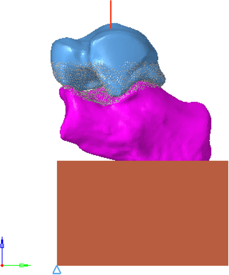
The body mass was 70 kg, and the compressive load acting on the calcaneus was about 700 N. All nodes on the articular surface of the talus were selected, and the coupling equation was established with the central node of the articular surface. The joint surface was established as a rigid surface, and a vertical z-axis negative concentrated load of 700 N was applied to the central node to simulate the single-leg standing condition of the human body. The specific direction is shown in Fig. 8.
Fig. 8.
Schematic diagram of load application
Finite element calculation
Abaqus 6.12.-1 was used as the solver and postprocessor for the finite element operation, and the Nlgeon large deformation calculation switch was turned on. The Newton-Raphson technique was used to solve the nonlinear equilibrium equations. The contact attribute and computation iteration control were set, and the global iteration number, computation time, and the maximum and minimum computation time steps were adjusted to improve the convergence.
Validation
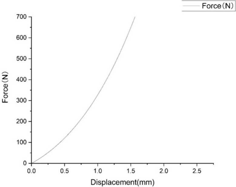
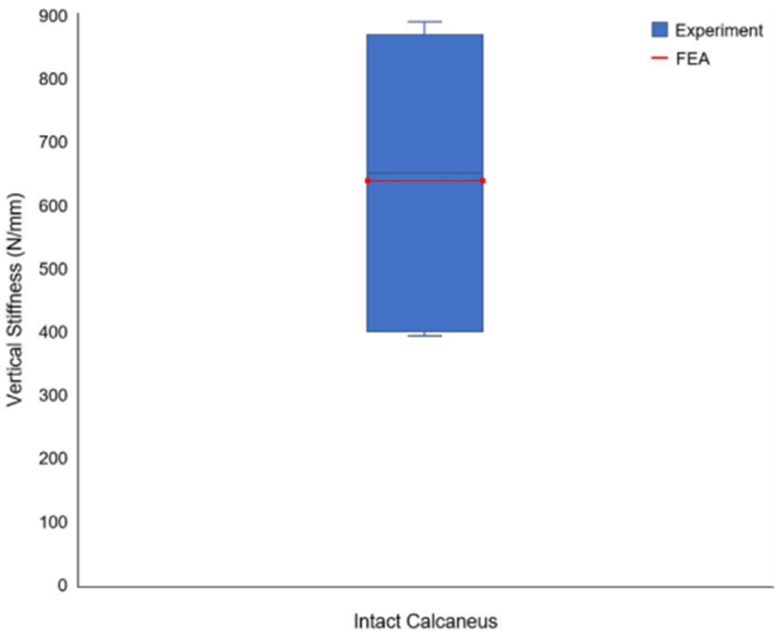
The stress distribution is shown in Fig. 9, the Force displacement curve is shown in Fig. 10, and the Degree of stiffness is shown in Fig. 11.
Fig. 9.
(A–B) Stress distribution
Fig. 10.
Force displacement curve
Fig. 11.
Degree of stiffness
Test of compressive mechanical properties
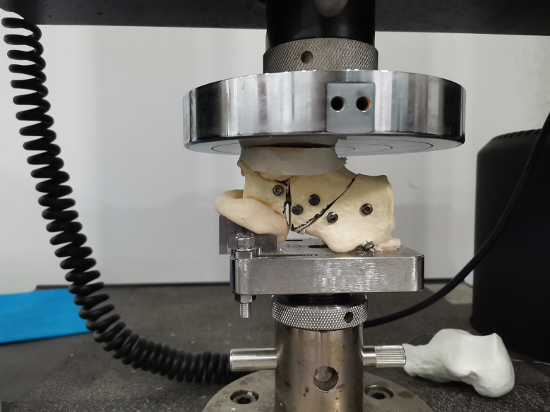
According to the Sanders classification of calcaneal fractures, 10 models of calcaneal fractures were made and fixed with a self-designed minimally invasive intramedullary stabilization system and ordinary titanium locking plate, respectively. The compressive force properties of the model under intramedullary fixation and plate fixation were tested by the Instron 5569 material testing machine. At room temperature, a 50KN sensor, fusion fixture, and Bluehill 3 control software were used. Set the load accuracy: +/-0.5% of the indicator reading load to 1/250 of the full-scale capacity of the sensor. Set the displacement accuracy to +/- 0.05% of the indicator reading. The maximum loading speed is 500 mm/min. Include 3D model and physical drawing of upper and lower fixture (Fig. 12).
Fig. 12.
The compression fixture was connected to the testing machine
Biomechanical evaluation index of the intramedullary stabilization system
A biomechanical test system tested the bending resistance and torsion resistance of the designed intramedullary stabilization system. The ratio of mechanical strength to the volume of the intramedullary stabilization system with different specifications was obtained by calculating the strength-to-volume ratio. The forced displacement, stiffness, and stress distribution of the two fixation methods were calculated respectively. To evaluate the compressive tolerance of minimally invasive and intramedullary stabilization systems based on the biomechanical analysis of calcaneal fracture fixation in vitro.
Results
Stress distribution of calcaneus
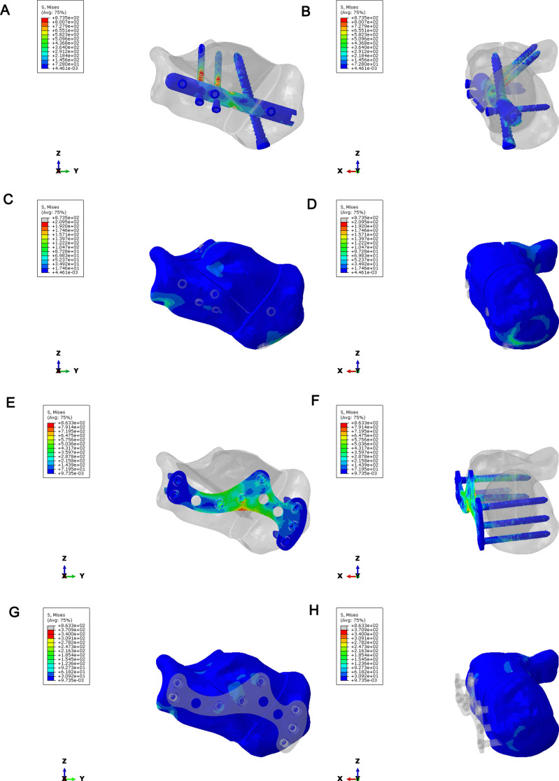
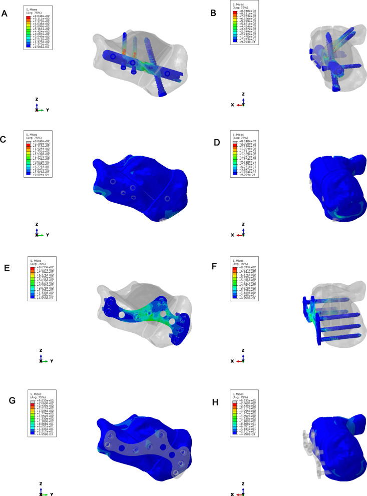
To compare the stress distribution of bone and implant between intramedullary fixation and locking plate fixation in calcaneal fractures; The maximum stress of the implant in the intramedullary fixation of Sanders type II calcaneal fractures was 873.5Mpa, and the maximum stress of the implant was located in the middle of the screw (Fig. 13A-B). The maximum bone stress was 209.5 MPa (Fig. 13C-D). In Sanders type II calcaneal fractures, the maximum stress of the implant was 863.3 MPa, the maximum stress of the implant was located in the middle of the plate and the middle of the screw (Fig. 13E-F), and the maximum stress of the bone was 370.9 MPa (Fig. 13G-H). The maximum implant stress of the Sanders III calcaneal fracture intramedullary nail was 884.8 MPa, the maximum implant stress was located in the middle of the screw (Fig. 14A-B), and the maximum bone stress was 230.8 MPa (Fig. 14C-D). In Sanders type III calcaneal fractures, the maximum stress of the implant was 863.3 MPa, the maximum stress of the implant was located in the middle of the plate and the middle of the screw (Fig. 14E-F), and the maximum stress of the bone was 266 MPa (Fig. 14G-H). Regardless of Sanders type II or Sanders type III calcaneal fractures, the maximum bone stress of intramedullary fixation and locking plate fixation was at the fixed position of the inferior border of the calcaneus.
Fig. 13.
Stress distribution of calcaneus in Sanders type II calcaneal fractures. (A–B) Implant stress in intramedullary fixation of Sanders type II calcaneal fractures. (C–D) Bone stress in intramedullary fixation of Sanders type II calcaneal fractures. (E–F) Stress of implants in plate fixation of Sanders type II calcaneal fractures. (G–H) Bone stress in plate fixation of Sanders type II calcaneal fractures
Fig. 14.
Stress distribution of calcaneus Sanders type III calcaneal fractures. (A–B) Implant stress in intramedullary fixation of Sanders type III calcaneal fractures. (C–D) Bone stress in intramedullary fixation of Sanders type III calcaneal fractures. (E–F) Stress of implants in plate fixation of Sanders type III calcaneal fractures. (G–H) Bone stress in plate fixation of Sanders type III calcaneal fractures
Force displacement and stiffness
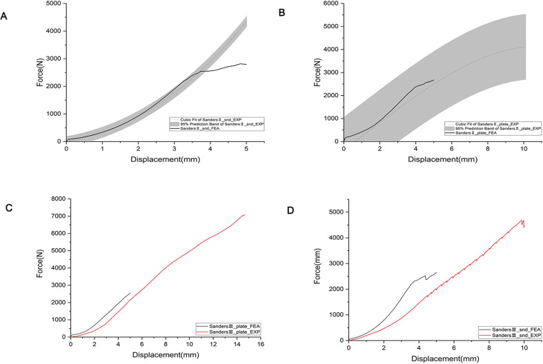
In Sanders type II fracture, two biomechanical tests were performed in the intramedullary fixation group and the plate fixation group, respectively. The finite element simulation results were within the 95% prediction interval of the mean results of the two experiments (Fig. 15A-B). In Sanders type III fracture, the single biomechanical test was performed in the intramedullary fixation group and the plate fixation group, and the force-displacement curves obtained by the intramedullary fixation group and the finite element fixation group had the same trend (Fig. 15C-D). There was a deviation in the force-displacement curves between the two groups, which may be caused by the differences in model establishment and contact between the finite element simulation and biomechanical testing. Stiffness reflects the ability of the calcaneal body to resist deformation and is defined as the ratio of the maximum vertical displacement of the calcaneus to the applied load. By comparing the different fixation methods of the two fracture types, the overall stiffness of the intramedullary fixation group was slightly higher than that of the locking plate fixation group.
Fig. 15.
Force displacement and stiffness. (A) Force displacement of Sanders II intramedullary fixation. (B) Force displacement of Sanders II plate fixation. (C) Force displacement of Sanders III intramedullary fixation. (D) Force displacement of Sanders III plate fixation
Effect of fixation methods on calcaneal pressure bearing
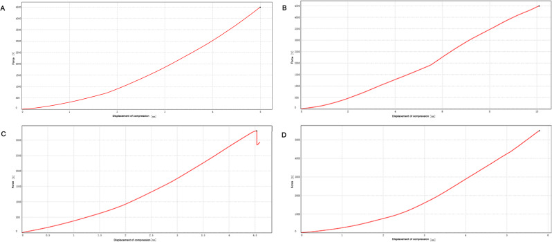
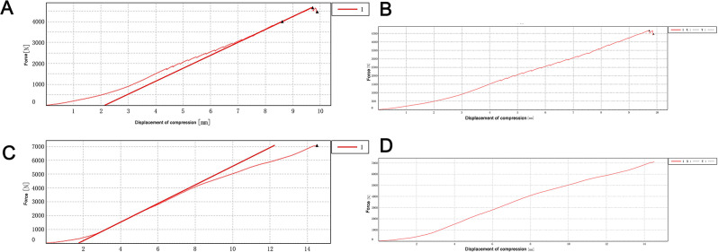
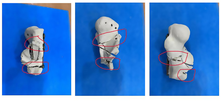
To test the compressive mechanical properties of different fixation types of calcaneal fractures. In Sanders type II calcaneal fractures, the maximum force value of the 4500 N compression plate fixation group and intramedullary fixation group showed no significant changes in the two groups of model samples (Fig. 16A-B). In the second experiment, the two groups were given a maximum compression force of 5500 N. The intramedullary fixation group loosened and broke at about 3302 N, while the plate fixation group showed no obvious abnormality when compressed to 5500 N (Fig. 16C-D). The Sanders type III calcaneal fractures model showed that the intramedullary fixation group had a small fracture sound at a pressure of about 1700 N and showed a stepwise fluctuation in the load-displacement curve (Fig. 17A-B), but the total force value showed an upward trend. The experiment continued, and then the fracture sound and the fluctuation of the curve were still shown, but the range was limited, and no obvious drop in force value was observed. When the pressure reached 4683.048 N, the fracture sound increased significantly, and the curve appeared to have an obvious inflection point, so the experiment was stopped manually. The screws at the lateral process and anterior tubercle of the sample were displaced, and no obvious dislocation of the bone block was observed. The model destruction is shown in Fig. 18. In the locking plate group, there was no abnormality in the sound and displacement curves during the whole experiment (Fig. 17C-D). Until the pressure reached 7092.895 N, which exceeded the intramedullary nail load by about 1.5 times, the experiment was manually terminated. The sample screw was cut out at the subtalar joint surface, and the bone block was obviously misplaced, and the damage is shown in Fig. 19.
Fig. 16.
Effect of fixation methods on calcaneal pressure bearing in Sanders type II calcaneal fractures model. The load-displacement curve of the intramedullary fixation group (A) and the load-displacement curve of the locking plate fixation group (B) were tested for the first time in Sanders type II calcaneal fractures model. The load-displacement curve of the intramedullary fixation group (C) and the load-displacement curve of the locking plate fixation group (D) were tested for the second time in Sanders type II calcaneal fractures model
Fig. 17.
Effect of fixation methods on calcaneal pressure bearing in Sanders type III calcaneal fractures model. The load-displacement curve of the intramedullary fixation group (A) and the load-displacement curve of the locking plate fixation group (B) were tested for the first time in Sanders type III calcaneal fractures model. The load-displacement curve of the intramedullary fixation group (C) and the load-displacement curve of the locking plate fixation group (D) were tested for the second time in Sanders type III calcaneal fractures model
Fig. 18.
Damage of the samples in the intramedullary fixation group
Fig. 19.
Failure of the samples in the locking plate fixation group
Discussion
Finite element method (FEM) is a new numerical method for solving problems in continuum mechanics and physics [17, 18]. Due to the unique ability of the finite element method to calculate complex shapes, loads and material properties, the finite element method has been widely used in orthopedic research, such as the analysis of biomechanical properties of bones [19], ligaments [20], joints [21], and other tissues [22] and organs [23]. In order to investigate the effects of intramedullary fixation and locking plate fixation on calcaneal fractures, we first extracted the features of the study area using the clinically obtained CT data and subsequently used the three-dimensional reconstruction method for finite element analysis. The main steps were as follows: Mimics 17 was used to reconstruct the cortical and cancellous bone 3D point cloud model of the calcaneus from CT images acquired in the previous clinical period, and Geomagic Studio 2012 was used to fit the point cloud model established by Mimics to an editable NURBS surface model. Then, the geometric solid model obtained from the above steps was imported into Hypermesh12 for mesh division, boundary conditions, material properties, and contact definition. Finally, it was submitted to ABAQUS 6.12 for finite element analysis. In this study, the biomechanical test and finite element simulation analysis were performed on the Sanders type II and III intramedullary fixation and locking plate fixation, respectively. In Sanders type II and Sanders type III fractures, the force-displacement curves and finite element results of intramedullary fixation and locking plate fixation had the same trend, but there were some deviations. By comparing the stiffness of the two fracture types with different fixation methods, it was known that the overall stiffness of the model in the intramedullary nail group was slightly greater than that of the plate. Hence, the effect of an intramedullary nail in fixing the fracture block was similar to that of the locking plate.
The main observation factors affecting fracture healing and the stability of the fracture end include the maximum displacement of the fracture free and the maximum displacement of the fracture fault [24–26]. Therefore, the fixation plate must ensure the anatomical reduction and stability of the fracture, allowing broken bone to bear the appropriate stress to promote bone healing. If a plate with excessive stiffness is used for internal fixation of a fracture, the stress diversion phenomenon may cause the plate to share the stress that should be borne by the broken bone, resulting in a significant decrease in the strength of the formed bone [27].
The load on bone is the sum of external and internal forces, and the combined force of these forces can lead to stress deformation of bone tissue [28]. The amount of deformation depends on the load and the ability of the bone tissue to resist deformation, that is, the Degree of strain occurs in accordance with the rigid structure of the bone tissue [29]. Therefore, it is necessary to investigate the relationship between stress distributions in the internal fixation system of fractures during bone healing. The finite element method can be used to establish the geometric model and boundary conditions of bone and bone plate that are basically consistent with the actual situation, and the accurate stress distribution can be obtained under the correct boundary conditions [30]. The shortcomings of experimental methods, such as ethics, difficulty in obtaining experimental subjects, poor repeatability, and difficulty in controlling experimental variables, can be effectively avoided [31]. The results of stress analysis of intramedullary fixation and locking plate fixation of Sanders type II and III fractures showed that under axial compression loading, the bone stress of Sanders type II fractures was the highest when fixed with locking plate, and the bone stress of Sanders type II fractures was the lowest when fixed with intramedullary. Under the Sanders type III fracture model, the stress of the intramedullary nail implant was slightly higher than that of the locking plate, and the screws under all conditions bore a large stress, with the risk of screw fracture.
On the basis of three-dimensional finite element analysis, a three-dimensional model was constructed to test the compressive mechanical properties of Sanders type III calcaneal fractures. In the intramedullary fixation group, a small fracture sound appeared at about 1700 N pressure, and the fracture sound increased significantly until 4683.048 N, and the curve showed obvious inflection points. The locking plate group did not show any abnormality throughout the experiment until 7092.895 N, which exceeded the intramedullary nail load by about 1.5 times. The compressive strength of intramedullary fixation was 59.62642 MPa, the fracture energy was 20469.87 mJ, and the stiffness was 481288.9 N/m. The fixed compressive strength of the locking plate was 90.30954 MPa, the fracture energy was 49628.11 mJ, and the stiffness was 489000.1 N/m. Thus, the compressive strength of the locking plate fixation group was higher than that of the intramedullary fixation group.
The study’s limitations include its reliance on data from a single healthy volunteer, potentially affecting the generalizability of the findings across diverse populations. Additionally, the material properties used in the finite element models, derived from literature, may not accurately represent the true mechanical behaviors under various physiological conditions. Furthermore, the simplified boundary conditions and load applications in the finite element analysis may not capture the complex biomechanical interactions in real-life calcaneal fracture scenarios, potentially limiting the predictive accuracy of fracture behavior. Future research should expand the sample size to enhance demographic representability and incorporate patient-specific material properties for more accurate biomechanical modeling. Additionally, developing models that simulate dynamic loading conditions will improve the clinical relevance of findings and deepen understanding of calcaneal fracture fixation methods.
Conclusion
Both intramedullary fixation and locking plate fixation for Sanders II and III calcaneal fractures have certain biomechanical stability, and locking plate fixation has potential application value in clinical practice. In the compression tests of three-dimensional solid models of Sanders type III and Sanders type II calcaneal fractures, the results of the two tests were too different to analyze statistical significance due to the small number of samples. Therefore, we will increase the samples and repeat the tests several times in the follow-up study to provide more data for reliable evidence.
Acknowledgements
Not applicable.
Abbreviations
- CT
Computed Tomography
- 3D
Three-dimensional
- IGES
Initial Graphics Exchange Specification
- FEM
Finite element method
Author contributions
Jiajun Wu authored the main manuscript text and produced the figures. Linyuan Zhang curated the CAD design and data. Chao Shen and Xiuhui Wang conducted critical reviews of the manuscript. Xiaoxiao Zhou conceptualized and developed the experimental design, and provided substantial revisions to the manuscript.
Funding
This study was partially supported by the Featured Clinical Discipline Project of Shanghai Pudong (PWYts2021-3), the Key Clinical Support Specialty Construction Project of Shanghai Hongkou District (HKLCFC202407), and the Youth Science and Technology Project of Shanghai Pudong New Area Health Commission (PW2024B-14).
Data availability
The datasets analyzed during the current study are available from the corresponding author upon reasonable request. Please contact Mr. Xiaoxiao Zhou via email at nataliabone@126.com or by phone number +86-21-65316175 for access.
Declarations
Ethics approval and consent to participate
Ethics approval was granted by the Institutional Review Board of Shanghai Pudong New Area Zhoupu Hospital. A healthy volunteer provided informed consent to participate in the study, following a thorough medical screening, including X-ray examinations to exclude foot and ankle injuries or diseases. All procedures complied with relevant ethical regulations.
Consent for publication
All authors affirm that they grant permission for the publication of identifiable details, which can include figures and tables within the manuscript. The authors understand that the information will be published without restriction upon the manuscript’s acceptance. Additionally, all study participants provided informed consent for the use of their data in this publication.
Competing interests
The authors declare no competing interests.
Conflict of interest
The authors declares that there are no conflicts of interest.
Footnotes
Publisher’s note
Springer Nature remains neutral with regard to jurisdictional claims in published maps and institutional affiliations.
First author: Jiajun Wu. Co-first author: Linyuan Zhang.
References
- 1.Galluzzo M, et al. Calcaneal fractures: radiological and CT evaluation and classification systems. Acta Biomed. 2018;89(1–s):138–50. [DOI] [PMC free article] [PubMed] [Google Scholar]
- 2.Basile A. Subjective results after surgical treatment for displaced intra-articular calcaneal fractures. J Foot Ankle Surg. 2012;51(2):182–6. [DOI] [PubMed] [Google Scholar]
- 3.Zhan J, et al. A modified tarsal sinus approach for intra-articular calcaneal fractures. J Orthop Surg (Hong Kong). 2019;27(2):2309499019836165. [DOI] [PubMed] [Google Scholar]
- 4.Ebraheim NA, et al. Sinus tarsi approach with trans-articular fixation for displaced intra-articular fractures of the calcaneus. Foot Ankle Int. 2000;21(2):105–13. [DOI] [PubMed] [Google Scholar]
- 5.Ceccarini P, et al. Minimally invasive sinus tarsi approach in Sanders II-III calcaneal fractures in high-demand patients. Med Glas (Zenica). 2021;18(1):322–7. [DOI] [PubMed] [Google Scholar]
- 6.Reinhardt S, et al. Interlocking nailing Versus Interlocking plating in intra-articular calcaneal fractures: a Biomechanical Study. Foot Ankle Int. 2016;37(8):891–7. [DOI] [PubMed] [Google Scholar]
- 7.Fascione F, et al. Surgical treatment of displaced intraarticular calcaneal fractures by a minimally invasive technique using a locking nail: a preliminary study. Foot Ankle Surg. 2019;25(5):679–83. [DOI] [PubMed] [Google Scholar]
- 8.Herlyn A, et al. Calcaneal fracture fixation using a new interlocking nail reduces complications compared to standard locking plates - preliminary results after 1.6 years. Injury. 2019;50(Suppl 3):63–8. [DOI] [PubMed] [Google Scholar]
- 9.Zwipp H, et al. Introduction of a new locking nail for treatment of Intraarticular Calcaneal fractures. J Orthop Trauma. 2016;30(3):e88–92. [DOI] [PubMed] [Google Scholar]
- 10.Tonetti J, Boudissa M, Kerschbaumer G, Seurat O. Role of 3D intraoperative imaging in orthopedic and trauma surgery. Orthop Traumatology: Surg Res. 2020;106(1):S19–25. [DOI] [PubMed] [Google Scholar]
- 11.Coakley M, Hurt DE. 3D printing in the laboratory. J Lab Autom. 2016;21:489–95. [DOI] [PMC free article] [PubMed] [Google Scholar]
- 12.Wolff S, Habboubi K, Sebaaly A, Moreau PE, Miladi L, Riouallon G. Correction of adult spinal deformity with a minimally invasive fusionless bipolar construct: preliminary results. Orthopaedics Traumatol Surg Res. 2019;105(6):1149–55. [DOI] [PubMed]
- 13.Kotani T, Akazawa T, Sakuma T, Nakayama K, Kishida S, Muramatsu Y, Sasaki Y, Ueno K, Iijima Y, Minami S, Ohtori S. Accuracy of powered surgical instruments compared with manual instruments for pedicle screw insertion: evaluation using o-arm-based navigation in scoliosis surgery. J Orthop Sci. 2018;23(5):765–9. [DOI] [PubMed] [Google Scholar]
- 14.Franke J, von Recum J, Suda AJ, Grützner PA, Wendl K. Intraoperative three-dimensional imaging in the treatment of acute unstable syndesmotic injuries. JBJS. 2012;94(15):1386–90. [DOI] [PubMed] [Google Scholar]
- 15.Chung KJ, Huang B, Choi CH, Park YW, Kim HN. Utility of 3D printing for complex distal tibial fractures and malleolar avulsion fractures: technical tip. Foot Ankle Int. 2015;36:1504–10. [DOI] [PubMed] [Google Scholar]
- 16.Kim HN, Liu XN, Noh KC. Use of a real-size 3D-printed model as a preoperative and intraoperative tool for minimally invasive plating of comminuted midshaft clavicle fractures. J Orthop Surg Res. 2015;10:91. [DOI] [PMC free article] [PubMed] [Google Scholar]
- 17.Souza JCM, et al. Carbon fiber-reinforced PEEK in implant dentistry: a scoping review on the finite element method. Comput Methods Biomech Biomed Engin. 2021;24(12):1355–67. [DOI] [PubMed] [Google Scholar]
- 18.Shi J, et al. Evaluation of the 3D finite element method using a tantalum rod for osteonecrosis of the femoral head. Med Sci Monit. 2014;20:2556–64. [DOI] [PMC free article] [PubMed] [Google Scholar]
- 19.Nakanowatari K, et al. Evaluation of vertebral bone strength with a finite element method using low dose computed tomography imaging. J Orthop Sci. 2022;27(3):574–81. [DOI] [PubMed] [Google Scholar]
- 20.Zhu J, Forman J. A review of finite element models of ligaments in the foot and considerations for practical application. J Biomech Eng. 2022;144(8). [DOI] [PubMed]
- 21.Li SJ, et al. Finite element analysis of the kinematic coupling effect of the joints around talus when Ponseti manipulation. BMC Musculoskelet Disord. 2021;22(1):682. [DOI] [PMC free article] [PubMed] [Google Scholar]
- 22.Freutel M, et al. Finite element modeling of soft tissues: material models, tissue interaction and challenges. Clin Biomech (Bristol Avon). 2014;29(4):363–72. [DOI] [PubMed] [Google Scholar]
- 23.Babayi M, et al. Three-dimensional finite element analysis of the pelvic organ prolapse: a parametric biomechanical modeling. Neurourol Urodyn. 2019;38(2):591–8. [DOI] [PubMed] [Google Scholar]
- 24.Ladurner A et al. Radiostereometric analysis allows assessment of the stability and inducible displacement of pelvic ring disruptions during healing: a case series. J Clin Med. 2020;9(11). [DOI] [PMC free article] [PubMed]
- 25.Sforza C, et al. Mandibular movements at maximum mouth opening and EMG activity of masticatory and neck muscles in patients rehabilitated after a mandibular condyle fracture. J Craniomaxillofac Surg. 2009;37(6):327–33. [DOI] [PubMed] [Google Scholar]
- 26.Luo Y, et al. Distribution of cracks in an anchored cavern under blast load based on cohesive elements. Sci Rep. 2022;12(1):4478. [DOI] [PMC free article] [PubMed] [Google Scholar]
- 27.Wright DJ, et al. Optimal fixation of the Capitellar Fragment in Distal Humerus fractures. J Orthop Trauma. 2021;35(7):e228–33. [DOI] [PubMed] [Google Scholar]
- 28.Wang L, et al. Development of a centrally vascularized tissue engineering bone graft with the unique core-shell composite structure for large femoral bone defect treatment. Biomaterials. 2018;175:44–60. [DOI] [PubMed] [Google Scholar]
- 29.Thabit AK, et al. Antibiotic penetration into bone and joints: an updated review. Int J Infect Dis. 2019;81:128–36. [DOI] [PubMed] [Google Scholar]
- 30.Yunus Emre T, et al. Effect of coronal fracture angle on the stability of screw fixation in medial malleolar fractures: a finite element analysis. Proc Inst Mech Eng H. 2022;236(6):825–40. [DOI] [PubMed] [Google Scholar]
- 31.Trivedi S. Finite element analysis: a boon to dentistry. J Oral Biol Craniofac Res. 2014;4(3):200–3. [DOI] [PMC free article] [PubMed] [Google Scholar]
Associated Data
This section collects any data citations, data availability statements, or supplementary materials included in this article.
Data Availability Statement
The datasets analyzed during the current study are available from the corresponding author upon reasonable request. Please contact Mr. Xiaoxiao Zhou via email at nataliabone@126.com or by phone number +86-21-65316175 for access.


