Abstract
In recent years, there have been many studies focused on improving the performance of active materials; however, applying these materials to active machines still presents significant challenges. In this study, we introduce a light-powered self-translation system for an asymmetric friction slider using a liquid crystal elastomer (LCE) string oscillator. The self-translation system was composed of a hollow slide, two LCE fibers, and a mass ball. Through the evolution of photothermal-induced contraction, we derived the governing equations for the system. Numerical simulations revealed two distinct motion modes: the static mode and the self-translation mode. As the mass ball moved, the LCE fibers alternated between illuminated and non-illuminated states, allowing them to effectively harvest light energy to compensate for the energy dissipation within the system. Unlike traditional self-oscillating systems that oscillate around a fixed position, the asymmetric friction enabled the slider to advance continuously through the oscillator’s symmetric self-sustained oscillation. Furthermore, we explored the critical conditions necessary for initiating self-translation as well as key system parameters that influence the frequency and amplitude of the oscillator and average speed of the slider. This self-translation system, with its simple design and ease of control, holds promising potential for applications in various fields including soft robotics, energy harvesting, and active machinery.
Keywords: asymmetric friction slider, self-translation, self-oscillation, liquid crystal elastomer, light-driven
1. Introduction
Active materials have the ability to alter their shape, size, and properties in response to external stimuli such as light [1,2], electricity [3,4], magnetic fields [5], heat [6,7], and pH [8], enabling them to perform specific tasks. Typical examples of active materials include polydimethylsiloxane [9], hydrogels [10,11], liquid crystal elastomers (LCEs) [12,13,14,15,16,17], and photo-responsive or thermal responsive polymers [18,19], etc. Active materials offer numerous advantages including self-healing, self-adaptation, lightweight, and flexible structure. Active materials hold significant research potential in fields such as soft robots [20,21,22,23,24], energy harvesting devices [25,26], mechano-logistic devices [27], self-propelled devices [28,29], and more.
Given the benefits of active materials, they have extensive potential to be employed in active machines. However, to enhance their efficiency and broader application, it is essential to develop an appropriate control method. Traditional approaches for controlling active machines encompass electronic component control and programmed design control [30,31]. However, these methods exhibit limitations such as the dependence on human intervention, the need for complex control systems, and high cost. In intricate work settings, these constraints may diminish the effectiveness of active machines, raise the safety risks, and potentially disrupt their proper functioning.
To address the issues above-mentioned, we adopted a new control method akin to the functioning of human organisms: self-oscillation. Self-oscillation refers to the periodic motion of a system under a constant external stimulus [32,33,34] and it can autonomously absorb external energy to counteract damping dissipation during motion. Its amplitude and frequency are typically determined by the system’s parameters. Additionally, self-oscillation demonstrates strong robustness [35]. Thanks to these advantages, self-oscillation systems hold significant potential for a wide range of applications in fields such as autonomous robots [21,22,23,24], energy-absorbing devices [25,26], sensors [36], cargo transport [37,38] and logical operations [39,40].
In recent years, the more types of oscillation modes are available, the more sophisticated autonomous devices may potentially be constructed such as bending [41,42,43], jumping [44,45,46], rolling [47,48,49,50], swinging [51,52], stretching and contracting [53,54,55,56], twisting [57,58], vibrating [59,60] and rotation [61,62,63], and even the synchronized motion of multiple coupled self-oscillators [64]. Many of these self-sustaining motions rely on nonlinear feedback mechanisms such as self-shading [65,66], photothermal solvent evaporation [67], and photothermal surface tension gradients [68]. These mechanisms disrupt the system’s initial equilibrium, enabling the active material to respond steadily and continuously to external stimuli, resulting in self-oscillations.
Among the various types of active materials, LCEs are an integration of liquid crystal (LC) mesogens and polymer networks, characterized by rapid response speed, significant macroscopic deformation, and reversible shape transformation [4,6,12,22,47,69]. They show great potential for enabling self-oscillation in various forms [34,35,41,47,50,65], thereby providing a strong foundation for the advancement of active machines. In this paper, we introduce a light-powered self-translation of an asymmetric friction slider using an LCE string oscillator. This device incorporates two LCE fibers and an oscillator enclosed within the slider, with each LCE fiber vertically linked inside the oscillator and the slider. The slider can continuously advance while the oscillator exhibits symmetric self-sustained oscillation under constant lighting conditions, without the need for periodic excitation forces or variable stiffness [70,71,72]. In contrast to traditional active machines, this system features a simple structure, easy control, and energy efficiency. These characteristics are particularly important for applications ranging from search and rescue operations to transportation, soft robotics, and active machinery.
The rest of this article is organized as follows. In Section 2, we derive the governing equations for the self-oscillation of the oscillator and the self-translation of the slider based on the evolution of photothermal-induced contraction. Section 3 describes the two distinct modes of motion: the static mode and the self-translation mode. Meanwhile, we explore the mechanism behind the system’s self-translation motion. In Section 4, through numerical calculations, we examine how various system parameters influence the amplitude and frequency of the oscillator as well as the average velocity of the slider. Finally, Section 5 provides a summary of the findings.
2. Theoretical Model and Formulation
This section introduces a theoretical model for the self-translation system under steady illumination. It encompasses the dynamic governing equations for the oscillator and slider and the evolution of photothermal-induced contraction.
2.1. Dynamics of the Self-Translation System
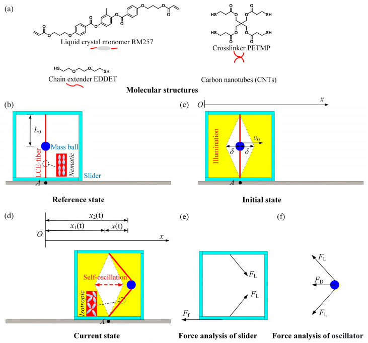
Figure 1 illustrates a light-powered self-translation of an asymmetric friction slider using an LCE string oscillator, which can continuously move forward, provided with a specific initial velocity of the mass ball and under predetermined lighting conditions. It comprises two photothermal-responsive LCE fibers with an original length of in stress-free state, a mass ball with a mass of , and a slider, as depicted in Figure 1b. Each LCE fiber is anchored at one end within the slider and at the other end to the mass ball in the vertical plane. Notably, photothermal-driven LCEs have garnered significant attention. The LCE fibers in our study can be fabricated using the method described in reference [14], with the molecular structures of the components used for synthesis shown in Figure 1a. In the reference state, the LC mesogens are aligned along the length direction of the LCE fibers. Upon heating beyond the nematic-to-isotropic phase transition temperature, the LC mesogens undergo a transition from the nematic phase to the isotropic phase [2,14,47]. This transition leads to a contraction along the length direction of the LCE fibers. When the LCE fibers have cooled down, the LC mesogens will revert to their oriented alignment. As a result, LCE fibers exhibit a reversible contraction and recovery behavior triggered by temperature fluctuations.
Figure 1.
Diagram of the self-translation system including (a) molecular structures, (b) reference state, (c) initial state, (d) current state, (e) force analysis of slider, and (f) force analysis of oscillator. The slider is subject to the tension of the LCE fibers and the friction force between the slider and the contact surface, while the mass ball experiences tension from the LCE fibers and the damping force . Under constant lighting conditions, the self-translation system can maintain continuous forward movement.
As depicted in Figure 1c, the illumination region is represented by the yellow portion, while the other is the non-illumination region. The distance between the initial position of the mass ball and the edge of the non-illumination region is denoted as . In the initial state, the mass ball is given an initial velocity as to the right horizontally, causing it to move in that direction while the tension in the LCE fiber gradually increases. As the mass ball enters the illuminated region, the temperature of the LCE fibers gradually increases due to the photothermal effect. As a result, the oriented nematic mesogens become isotropic, causing the fibers to contract. This accelerates the rate of tension growth, which leads to a gradual decrease in the velocity of the mass ball until it reaches zero, after which it moves in the opposite direction. After some time, when the mass ball enters the non-illuminated region, the temperature of the LCE fibers gradually decreases, causing the LC mesogens to revert to their oriented alignment, and the photothermal-induced contraction gradually recovers. When the mass ball returns to its initial position, its inertia carries it to further move to the left. Upon entering the illumination region on the left, the LCE fibers contract again in response to light, causing the tension increase, and the velocity of the mass ball continues to decrease to a standstill. The mass ball then moves back to the initial position, even to the right.
Due to the tension from the LCE fibers, the slider may move left or right during the oscillation of the mass ball. Considering the asymmetry contacting between the slider and the contact surface, the slider experiences different frictional forces with the different friction coefficients when moving rightward and leftward. Therefore, under steady illumination, the slider may translate toward one direction accompanied with the mass ball oscillating between right and left.
To describe the system’s motion, designate point A on the contact surface as a reference, as shown in Figure 1b. During the motion, the direction of horizontal motion to the right is defined as positive. The self-translation system experiences the tension of the LCE fibers and the friction force between the slider and the contact surface, as illustrated in Figure 1e. It is assumed that the gravitational force acting on the mass ball is much less than the vertical component of the tension in the LCE fibers, and can be neglected. Therefore, as the mass ball moves, the symmetry of the LCE fibers connecting both ends ensures that the vertical components of tension counterbalance each other, and the mass ball moves exclusively in the horizontal direction. Thus, in the horizontal direction, the governing equations for the motion of the slider can be expressed as follows:
| (1) |
where indicates the relative displacement between the mass ball and the slider, is the total weight of the self-translation system, and represents the acceleration of the slider. The relationship between the tension and the elongation of the LCE fibers can be expressed as follows:
| (2) |
where represents the elastic coefficient of the LCE fibers, and denotes the photothermal-induced contraction of the LCE fibers. The frictional force between the slider and the surface can be described as:
| (3) |
where is the coefficient of friction between the system and the surface, is the acceleration due to gravity, and describes the direction of the slider’s frictional force. When the slider is moved to the right, and . When the slider is moved to the left, and . When the slider is stationary, .
Meanwhile, the mass ball experiences tension from the LCE fibers and damping force experienced by the mass ball during its movement, as depicted in Figure 1f. In the horizontal direction, the governing equation for the mass ball can be expressed as:
| (4) |
where denotes the absolute acceleration of the mass ball. Based on the geometric relationship, it becomes evident that:
| (5) |
where denotes the absolute displacement of the mass ball, and denotes the displacement of the slider. For simplicity, the damping force of the mass ball is assumed to be proportional to its velocity, given by the formula:
| (6) |
where denotes the damping coefficient, and represents the absolute velocity of the mass ball.
To calculate the tension in Equation (2), it is necessary to first evaluate the photo-thermal-induced contraction ε(t), with the specifics outlined in the following section.
2.2. Photothermal-Induced Contraction
This section focuses on the photothermal-induced contraction in LCE fibers. The LCE fibers exhibited a reversible contraction and restoration response induced by changes in temperature. For simplicity, the photothermal-induced contraction was presumed to have a linear relationship with the temperature difference of the LCE fiber [2,6,14,47], which can be expressed as follows:
| (7) |
where is the thermal contraction coefficient.
Due to the photothermal effect, the temperature of the LCE fiber increases under illuminated conditions. Considering that the length of the LCE fiber is much larger than its cross-sectional radius, we assumed that heat exchange occurs rapidly enough for the temperature within the photothermal-responsive LCE fiber to remain uniform. It is worth noting that while the LCE fiber is being heated, it simultaneously dissipates heat to the surrounding environment. Therefore, under steady illumination, the temperature difference of the LCE fiber can be expressed as
| (8) |
where represents the photothermal flux from the steady illumination, denotes the heat transfer coefficient, and is the heat capacity. Here, s the limited temperature difference for the LCE fiber when a constant light is applied, and represents the thermal relaxation time, reflecting the rate of heat exchange between the LCE fiber and its surroundings. It is worth mentioning that in this work, the LCE fiber switched between the illuminated and non-illuminated regions. For the case of LCE fibers in the non-illuminated region, the current photothermal flux was set as for .
3. Two Motion Modes and Mechanism of Self-Translation
In this section, we examine the two motion modes within the LCE string oscillator and slider: the static mode and the self-translation mode. Additionally, we delve into the corresponding self-translation mechanism.
3.1. Two Motion Modes
According to the theoretical model for the self-translation system under steady illumination, we further nondimensionalized the governing Equations (1)–(8), as presented in Appendix A. From Appendix A, the light-powered self-translation can be determined for a given set of dimensionless parameters: , , , , , , , , , and . Thus, it is essential to determine the specific values of the dimensionless parameters required in the model. Utilizing data from existing experiments [14,73,74,75,76], we gathered the typical material properties and geometric parameters in Table 1 and the corresponding dimensionless in Table 2. Subsequently, these parameter values were used to study the light-powered self-translation system.
Table 1.
Material properties and geometric parameters.
| Parameter | Definition | Value | Units |
|---|---|---|---|
| Photothermal flux | 0~500 | W/m2 | |
| Contraction coefficient | 0~5 × 10⁻³ | /°C | |
| Elastic coefficient | 1~3 | N/m | |
| Thermal drive relaxation time | 0.01~0.1 | s | |
| Mass of the mass ball | 0~10 | g | |
| Mass of the self-translation system | 0~10 | g | |
| Damping coefficient | 0~0.5 | mg·mm/s | |
| Initial velocity | 0~0.1 | m/s | |
| Non-illuminated width | 0~0.1 | m | |
| Original length of LCE fiber | 0~0.2 | m | |
| Coefficient of forward friction | 0~0.2 | ||
| Coefficient of receding friction | 0~0.2 |
Table 2.
Dimensionless parameters.
| Parameter | ||||||||
|---|---|---|---|---|---|---|---|---|
| Value | 0~1 | 0~10 | 0~0.1 | 0~0.5 | 1~3 | 0.1~2 | 0~1 | 1~3 |
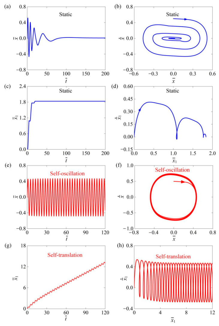
Figure 2 illustrates the time history curves and phase trajectories for the two motion modes of the self-translation system. The parameters used in the calculation were set as follows: , , , , , , , , and . The results indicate that the self-translation system exhibits two motion modes, namely the static mode and the self-translation mode. Figure 2a–d depicts the static mode of the system without photothermal flux at , where the relative displacement and velocity between the mass ball and the slider gradually diminished due to damping, and the slider moved slowly over time as a result of friction. Eventually, the oscillator and slider rested on the contact surface, which is named as the static mode. Figure 2e–h is shown as , where the mass ball is initially given a velocity to the right to reach the illumination region, and both the relative velocity of the mass ball and the velocity of the slider gradually increase over time, and finally remains constant. Therefore, the mass ball enters the self-oscillation mode. While the slider moves forward accompanied with oscillating back and forth, it means that the slider has achieved the motion of self-oscillation-driven translation, which is named as the self-translation mode.
Figure 2.
The time history curves and phase trajectories of the two motion modes of the mass ball and the slider are plotted. (a–d) The static mode with . (e–h) The self-translation mode with . We configured the remaining system parameters as follows: , , , , , , , and . The mass ball and slider could exhibit two types of motion modes: static mode and self-translation mode.
3.2. Mechanism of Self-Translation
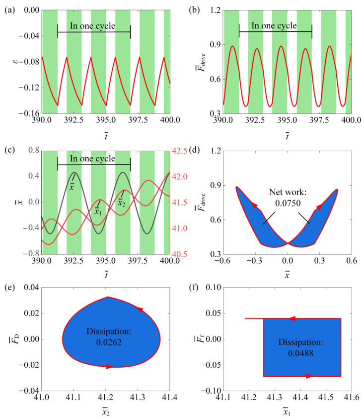
In the light-powered self-translation of an asymmetric friction slider using an LCE string oscillator, both damping and frictional dissipation occur. We investigated the conversion between energy input energy dissipation, which can be calculated according to Appendix B. Figure 3 depicts several key physical quantities related to the self-translational motion of the slider, as observed in the typical case shown in Figure 2e,f. Figure 3a shows the photothermal-induced contraction of the LCE fibers over time, demonstrating periodic variation. The green-shaded area indicates that the LCE fibers are in the illumination region during the mass ball’s self-oscillation. Correspondingly, Figure 3b illustrates that the equivalent driving force also has periodic changes over time. Figure 3c illustrates the relative displacement between the mass ball and the slider, the displacement of the slider, and the absolute displacement of the mass ball over time. It is evident that the relative displacement between the mass ball and the slider varied periodically with time, while both the displacement of the slider and the absolute displacement of the mass ball increased continuously over time. The dependence between the force and the relative displacement formed a clockwise closed loop during one period of the mass ball’s self-oscillating motion, as shown in Figure 3d. This closed loop represents the net work undertaken by the horizontal component of the LCE fiber tension over a cycle. The calculated value was . Figure 3e,f illustrates the dependence between the damping force and the absolute displacement and the dependence between the friction and the absolute displacement over a self-oscillation cycle. It is evident that both the damping force and the frictional force traced out a counterclockwise closed loop over a cycle, with the areas of these loops calculated to be and , respectively. Clearly, over one self-oscillation cycle, the net work undertaken by the tension of the horizontal component of the LCE fibers could entirely offset the work conducted by the damping force and the frictional force. This balance ensures the self-translation of the entire system under constant photothermal flux conditions.
Figure 3.
The mechanism of self-translation of an asymmetric friction slider for the typical case in Figure 2e–h. (a) The time history curve of . (b) The time history curve of . (c) The time history curve of , , . (d) The dependence between and . (e) The dependence between and . (f) The dependence between and . The net work undertaken by counteracts the energy dissipation caused by and , thereby maintaining the self-translation.
4. Impact of System Parameters on the Self-Translation
The following dimensionless parameters exist in the above theoretical model including , , , , , , , , , and . In this section, we examine the trigger conditions for self-translation as well as the dimensionless frequency and amplitude of the mass ball’s self-oscillation and the dimensionless average speed of the slider’s self-translation.
4.1. Influence of Photothermal Flux
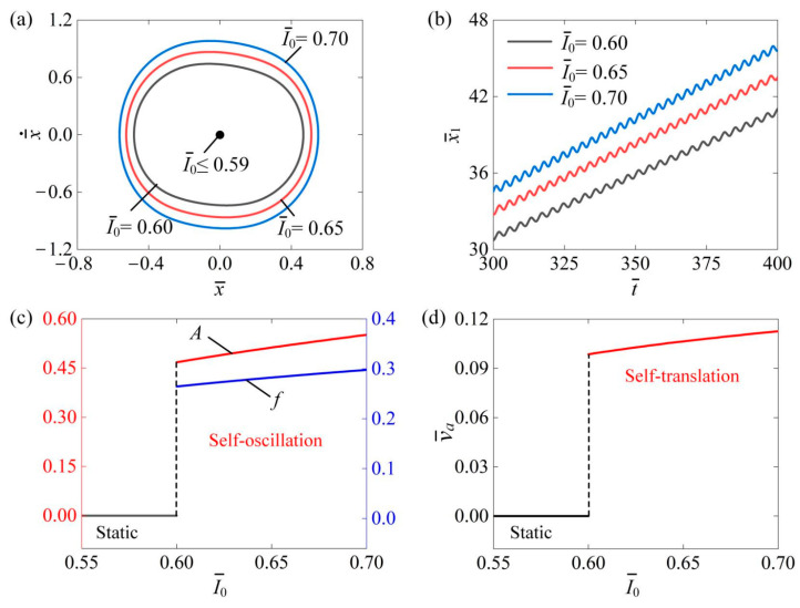
Figure 4 shows the impact of photothermal flux on the self-translation system. The remaining system parameters are as follows: , , , , , , , , and . Figure 4a displays the limiting circles of the mass ball’s self-oscillation at three different light intensities: , , and . A critical photothermal flux of approximately was identified for triggering self-translation. When the photothermal flux is above this threshold, the energy input to the system compensates for the energy dissipation, enabling self-translation. Notably, the size of the limit circle increases with rising photothermal flux during self-translation. Figure 4b illustrates the displacement of the slider over time at , , and . As the photothermal flux increases, the slider’s displacement also rises over the same duration. In Figure 4c, it is evident that both the amplitude and frequency increased with the increase in . This enhancement occurs because higher photothermal flux amplifies the photothermal-induced contraction of the LCE fibers, thereby generating a greater equivalent driving force on the slider, which enables it to perform more net work. Furthermore, as shown in Figure 4d, the average speed of the slider correspondingly increased with the photothermal flux. These results suggest that increasing the photothermal flux can enhance the engineering applications of the slider’s self-translation.
Figure 4.
The effect of photothermal flux on the self-translation system, with the remaining system parameters set as follows: , , , , , , , and . (a) The limiting circles of the mass ball. (b) Displacement–time curves of the slider. (c) The amplitude and frequency of self-oscillation. (d) The average velocity of self-translation. As photothermal flux increased, an upward trend was observed in both the and of the mass ball’s self-oscillation as well as in the of the slider’s self-translation.
4.2. Influence of Contraction Coefficient
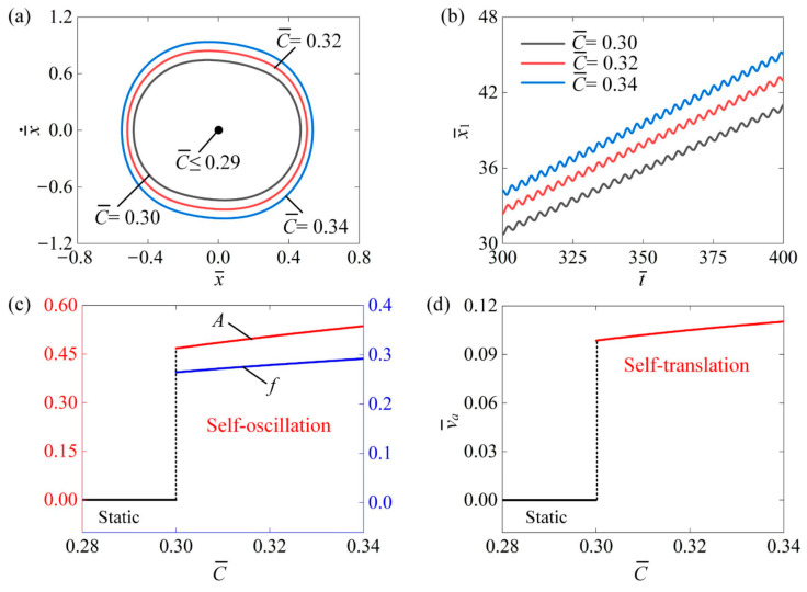
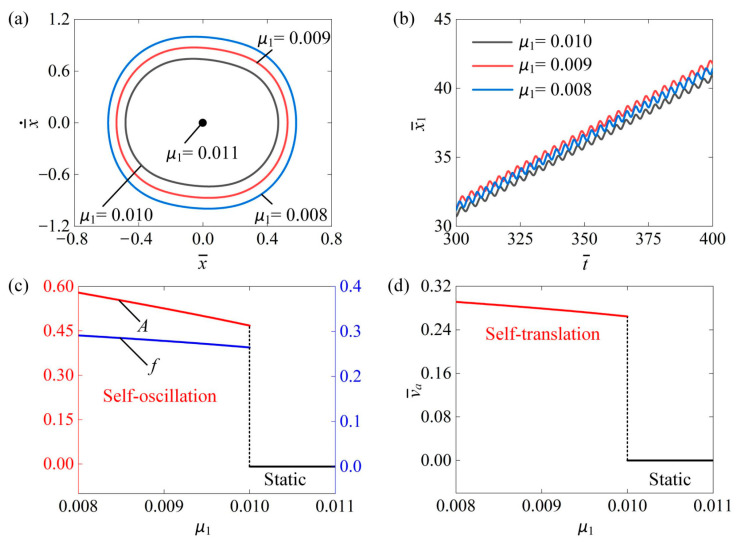
Figure 5 explores the effect of the contraction coefficient of the LCE fiber on the self-translation system. The other system parameters are as follows: , , , , , , , , and . Figure 5a shows the limiting circles of the mass ball’s self-oscillation at three different contraction coefficients, namely , , and . A critical contraction coefficient of approximately was identified as the threshold for triggering self-translation. When the contraction coefficient exceeds this threshold, the energy input to the system offsets energy dissipation, facilitating self-translation. Importantly, the size of the limit circle increases with a higher contraction coefficient during self-translation. Figure 5b depicts the displacement of the slider over time at , , and . As the contraction coefficient rises, the displacement of the slider also increases over the same period. In Figure 5c, it is clear that both the amplitude and frequency increased with the contraction coefficient. This enhancement occurs because greater contraction coefficient amplifies the photothermal-induced contraction of the LCE fibers, resulting in a stronger equivalent driving force on the slider, which allows it to perform more net work. Additionally, as illustrated in Figure 5d, the average speed of the slider correspondingly rose with an increasing contraction coefficient. These findings indicate that enhancing the contraction coefficient can improve the efficient conversion of energy from light to mechanical energy.
Figure 5.
The impact of the contraction coefficient of the LCE fibers on the self-translation system. The remaining system parameters are configured as follows: , , , , , , , and (a) The limiting circle of the mass ball. (b) Displacement–time curves of the slider. (c) The amplitude and frequency of self-oscillation. (d) The average velocity of self-translation. As the contraction coefficient of the LCE fibers increased, both the and of the mass ball’s self-oscillation as well as the of the slider’s self-translation, demonstrated an upward trend.
4.3. Influence of Non-Illuminated Width
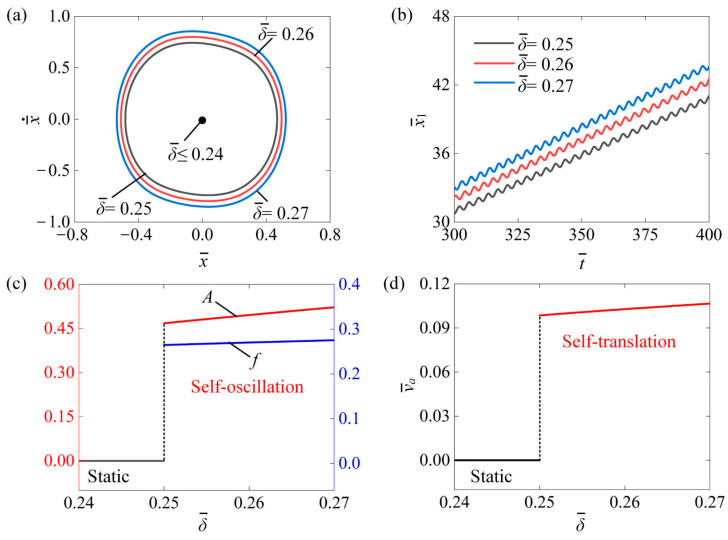
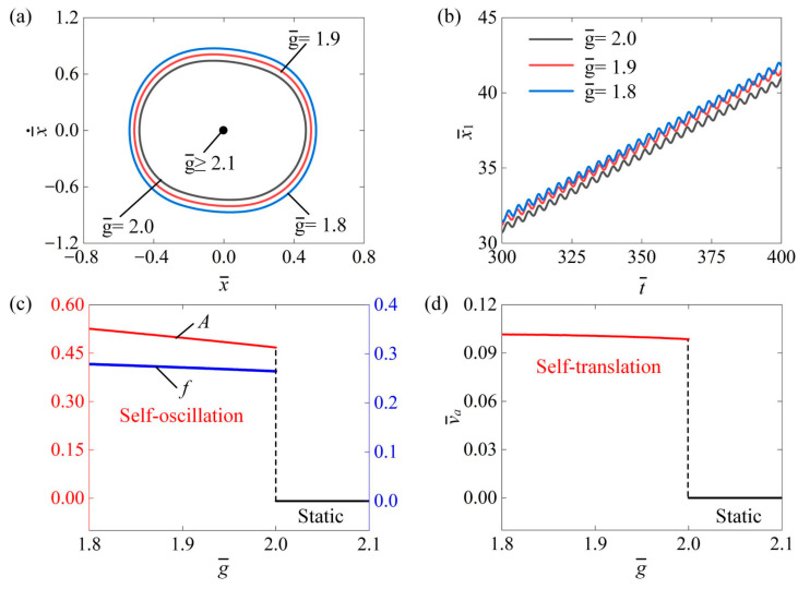
Figure 6 discusses how the non-illuminated width affects the self-translation system. In the calculation, we set , , , , , , , , and . Figure 6a depicts the size of the limit cycles under three different non-illuminated widths for , and . A critical non-illuminated width of about can be obtained to trigger self-translation. When , the system is in a static mode, while the system is in the self-translation mode when . This is because a larger non-illuminated width provides more time for the LCE fibers to recover from the photothermal-induced contraction, allowing them to absorb more light energy in the illuminated region. Figure 6b presents the time history curve of displacement of the slider under the non-illuminated width of , and . It can be easily observed that the displacement of the slider increased as increased. Figure 6c shows that as increased, the self-oscillation amplitude and frequency increased. Figure 6d shows that with the increase in the non-illuminated width, the average speed of the slider also increased. For the self-translation system, it is essential to induce photothermal-induced contraction in the illuminated region. Additionally, sufficient time for recovery from this contraction is also required. As the photothermal-induced contraction approaches its maximum value (illustrated in Figure 3a), increasing the non-illuminated width can enhance the recovery process. This, in turn, allows for a greater absorption of light energy in the illuminated region. Therefore, increasing the non-illuminated width results in an increase in self-oscillation amplitude , frequency , and translational average speed .
Figure 6.
The influence of non-illuminated width on the self-translation system. The remaining system parameters are configured as follows: , , , , , , , and . (a) The limiting circle of the mass ball. (b) Displacement–time curves of the slider. (c) The amplitude and frequency of self-oscillation. (d) The average velocity of self-translation. Increasing the non-illuminated width resulted in an increase in self-oscillation , , and translational .
4.4. Influence of Elastic Coefficient
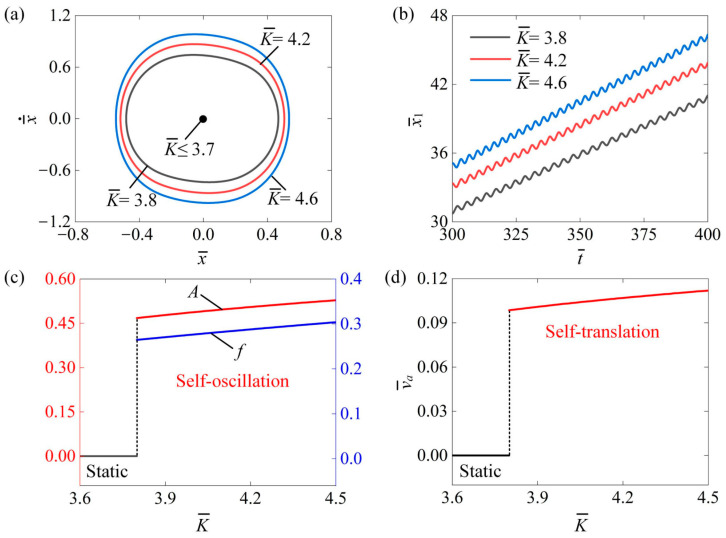
Figure 7 examines the impact of the coefficient of elasticity on the self-translation system under parameters such as, , , , , , , and . Figure 7a illustrates the limit circles of the mass ball’s self-oscillation at three different elasticity coefficients , , and . The results indicate that there is a critical value of that transitions the mass ball from a static state to a self-oscillation state. When the is below this critical value, the mass ball remains static; however, when it exceeds the critical value, the mass ball enters a state of self-oscillation. As the increases, the boundary of the self-oscillation of the mass ball also expands. Figure 7b displays the absolute displacement of the slider’s self-translation over time for different elasticity coefficients as , , and Clearly, as the increased, the also rose. This can be attributed to the fact that a higher enhances the equivalent driving force of the LCE fibers, enabling the slider to cover greater distances. Figure 7c demonstrates the effect of on the amplitude and frequency of the mass ball’s self-oscillation. Figure 7d shows how influences the average speed of the slider’s self-translation. As increases, and , along with , all rise. This suggests that a higher results in a greater equivalent driving force from the LCE fibers, leading to increased , , and .
Figure 7.
The impact of the elastic coefficient of the LCE fibers on self-translation. The remaining system parameters are defined as follows: , , , , , , , and . (a) The limiting circle of the mass ball. (b) Displacement–time curves of the slider. (c) The amplitude and frequency of self-oscillation. (d) The average velocity of self-translation. As the elasticity coefficient increases, the system demonstrated a noticeable rise in the and of the mass ball’s self-oscillation motion and the of the slider’s self-translation motion.
4.5. Influence of Initial Velocity
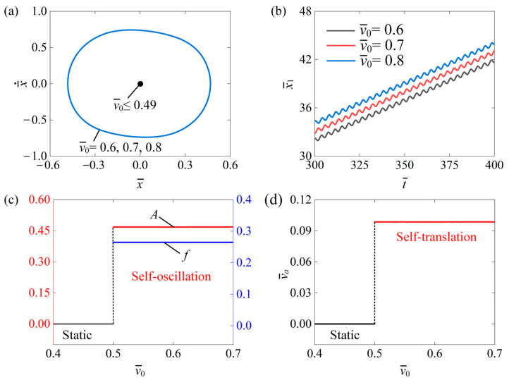
Figure 8 shows the influence of the initial velocity on the self-translation system. In the calculation, we set , , , , , , , and . Figure 8a plots the limit circles of the mass ball’s self-oscillation relevant to different initial velocities. A critical velocity of about existed in the phase transition between static mode and self-translation mode while exhibited static mode due to the fact that insufficient energy was input to compensate for the damping dissipation. The self-translation mode was triggered at , and , which had an identical limit circle, as shown in Figure 8a. Figure 8b depicts the absolute displacement of the slider’s self-translation over time. It was observed that during the same time period, an increase in the initial velocity corresponded to an increase in the slider’s displacement. This indicates that a higher initial velocity results in greater initial kinetic energy within the system, allowing the slider to cover a longer distance during its translation motion. Figure 8c illustrates how the amplitude and frequency change with . Both the and of self-oscillation displayed no variation along with . Figure 8d illustrates how the average velocity of the slider’s self-translation varied with the initial velocity . Once the system is in the self-translation state, the average velocity will also remain unaffected. This is due to the fact that the initial conditions do not influence the behavior of self-oscillation, as these are intrinsic characteristics of the process. Consequently, the self-translation driven by continuous oscillation is likewise unaffected by the initial conditions.
Figure 8.
The impact of initial velocity on the self-translation system. The other parameters of the system are configured as follows: , , , , , , , and . (a) The limiting circle of the mass ball. (b) Displacement-time curves of the slider. (c) The amplitude and frequency of self-oscillation. (d) The average velocity of self-translation. As the initial velocity increases, the and of the mass ball’s self-oscillation and the of the slider’s self-translation tend to be constant.
4.6. Influence of the Coefficient of the Force of Friction
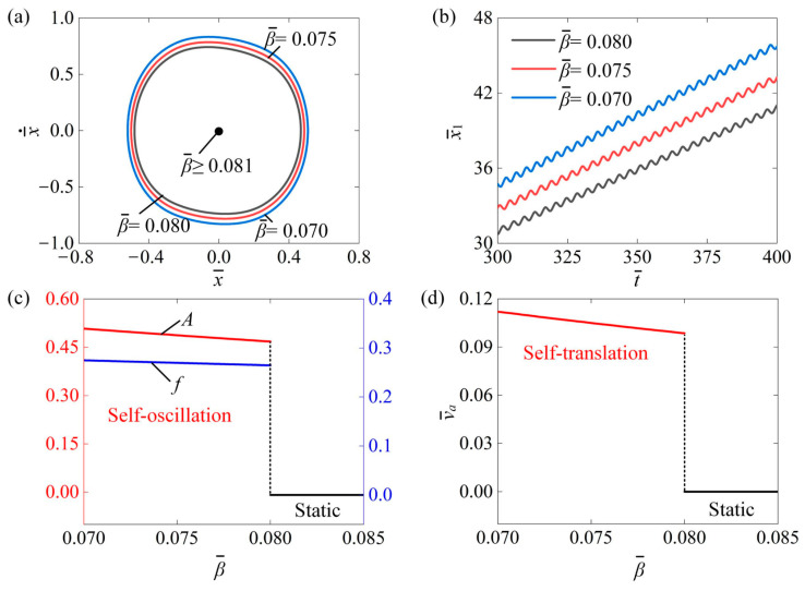
In this section, we explore the impact of friction coefficient on the self-translation system. In the calculation, we set , , , , , , , and . Figure 9a depicts the limit circles of the mass ball’s self-oscillation for three different friction coefficients: , , and . A critical friction coefficient can be numerically calculated for triggering self-translation, with a value about . This outcome indicates that the slider remains in a static pattern when and transitions to a self-translation pattern when . This is because as the friction coefficient increases, the net work generated by the equivalent driving force is no longer sufficient to counteract the damping dissipation necessary for maintaining self-translation. Figure 9b presents the time history curve of the slider’s displacement under the three friction coefficients of , , and . As the friction coefficient decreases, the displacement of the slider within the same time increases. Figure 9c illustrates that as the friction coefficient increased, both the self-oscillation amplitude and frequency decreased. This phenomenon can be attributed to the fact that as the friction coefficient increases, more energy is dissipated in the system due to friction, resulting in a smaller amplitude. Furthermore, the average speed of the slider also decreases with the increase in friction coefficient, as shown in Figure 9d. Therefore, it can be concluded that a smaller friction coefficient allows the slider to reach a self-translation pattern more easily.
Figure 9.
The impact of friction coefficient on the self-translation system under the given parameters of , , , , , , , and . (a) The limiting circle of the mass ball. (b) Displacement–time curves of the slider. (c) The amplitude and frequency of self-oscillation. (d) The average velocity of self-translation. As the friction coefficient increased, both the , the and the of slider exhibited a downward trend.
4.7. Influence of Damping Coefficient
Figure 10 analyzes the impact of the damping coefficient on the self-translation of the slider. The parameters were set for , , , , , , , and . Figure 10a describes the three limit cycles of the slider at the damping coefficients of , , and . Observations indicated that the size of the limit cycle increased as the damping coefficient decreased, and there was a critical damping coefficient of about for triggering self-translation. This is because the energy input to the system was insufficient to counteract the damping dissipation for , resulting in the system being in a static pattern. The input of energy to the system was capable of compensating for the dissipation caused by damping for , thus the system was in a self-translation pattern. In Figure 10b, the time history curve of the slider’s displacement is shown under the damping coefficients of , , and . These findings suggest that as the damping coefficient decreases, the slider travels greater distances simultaneously. Figure 10c shows that as the damping coefficient increased, the self-oscillation amplitude decreased, while the frequency nearly remained constant. This occurs because a larger damping coefficient leads to greater energy dissipation within the system, which in turn produces a smaller amplitude. Additionally, it can be noted that the self-oscillation frequency remains nearly constant, regardless of changes in the damping coefficient. This is because the damping coefficient does not affect the inherent period. Moreover, as the damping coefficient increases, the average speed of the slider decreases, as illustrated in Figure 10d. To enable quicker self-translation in engineering applications, we can consider reducing the damping coefficient appropriately.
Figure 10.
The impact of damping coefficient on the self-translation system under the given parameters of , , , , , , , and (a) The limiting circle of the mass ball. (b) Displacement–time curves of the slider. (c) The amplitude and frequency of self-oscillation. (d) The average velocity of self-translation. As the damping coefficient increased, both the and of the mass ball and the of slider showed a decreasing trend.
4.8. Influence of Friction Coefficient Ratio
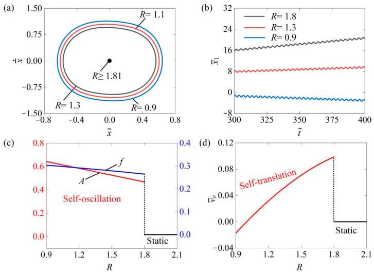
Figure 11 investigates the influence of the friction coefficient ratio on the self-translation system. The parameters were as follows: , , , , , , , and . Figure 11a illustrates the limit circles of the mass ball’s self-oscillation under three different friction coefficients ratios of , , and . It is clear that the limiting circle of the mass ball’s self-oscillation decreases as the increases. There was a critical value of that triggered the transition of the mass ball from a self-oscillation state to a static state. When the was below , the net work carried out by the equivalent driving force was sufficient to compensate for damping dissipation, allowing the mass ball to maintain a self-oscillation state. Conversely, when the exceeded , the damping dissipation surpassed the net work undertaken by the , resulting in the mass ball becoming static. In Figure 11b, we observed the absolute displacement of the slider’s self-translation over time during the same period in the , , . Over the same time period, an increase in resulted in a decrease in . This can be attributed as follows: as the increases, the rising friction force, which increases the work and damping dissipation, ultimately hinders the slider’s movement and reduces its travel distance. Notably, when exceeds , the slider moves forward; otherwise, it exhibits backward motion during self-translation. Figure 11c illustrates how the amplitude and frequency of the mass ball’s self-oscillation changed with the . When the was below the critical value of , the mass ball remained in a state of self-oscillation. In contrast, when exceeded this critical value, the mass ball entered a static state. Figure 11d displays the average velocity of the slider’s self-translation in relation to . When the exceeded the critical value of , the slider remained in a static state. Conversely, if the was below , the slider remained in a self-translation state. As the increased, the and of the mass ball decreased. This can be understood as the increasing friction leading to greater work undertaken against damping dissipation, resulting in lower and of the mass ball’s self-oscillation. When , the absolute value of the slider’s average speed decreases as the increases. Conversely, when , the absolute value of the slider’s average speed increases as the increases. This occurs because in the case of , during the slider’s self-translation, the resistance to the right is greater than that to the left, causing the slider to move left. As the increases, the resistance to leftward movement also increases, resulting in a smaller average speed of the slider’s self-translation. In contrast, at , the resistance to the left is greater than that to the right, leading the slider to move right. Here, a higher also increases the resistance to leftward movement, which in turn results in a higher average speed of the slider’s self-translation.
Figure 11.
The impact of the friction coefficient ratio on the self-translation system. The remaining system parameters are configured as follows: , , , , , , , and . (a) The limiting circle of the mass ball. (b) Displacement–time curves of the slider. (c) The amplitude and frequency of self-oscillation. (d) The average velocity of self-translation. As the increased, both the and of the mass ball’s self-oscillation exhibited a declining trend. At , the absolute value of the slider’s in self-translation decreases as the increases. In contrast, at , the absolute value of the average velocity increases with a higher .
4.9. Influence of the Mass Ratio
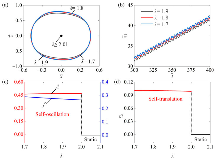
This section investigates the impact of mass ratio on the self-translation system for the given parameters of , , , , , , , and . Figure 12a plots the limit cycle under different mass ratios of , , and . It can be clearly seen that the size of the limit cycle decreased as the mass ratio increased, and there was a critical mass ratio of about for triggering self-translation. When , the input energy to the system was insufficient to counteract the dissipation caused by damping, leading to a static state. Conversely, when , the input energy could adequately offset the damping dissipation, allowing the system to enter a self-translation pattern. Figure 12b presents the displacement–time curves of the slider of , , and . As the mass ratio decreased, the displacement of the slider became farther at the same time. Additionally, as shown in Figure 12c, the amplitude remained relatively constant as the mass ratio increased, while the frequency decreased with a rising mass ratio. This happens because, as the mass ratio of the slider to the ball increases, the friction force between the slider’s body and the contact surface also rises. Consequently, the system dissipates more energy due to this friction, resulting in a decreased frequency of the ball. In addition, the average speed of the slider also decreases, as shown in Figure 12d. Therefore, decreasing the mass ratio can improve the self-translation of the slider.
Figure 12.
The impact of mass ratio on the self-translation system. The remaining system parameters are configured as follows: , , , , , , , and . (a) The limiting circle of the mass ball. (b) Displacement–time curves of the slider. (c) The amplitude and frequency of self-oscillation. (d) The average velocity of self-translation. As the mass ratio increased, it was noticeable that the amplitude remained relatively constant, while the frequency and the of the slider’s self-translation decreased.
4.10. Influence of the Gravitational Acceleration
Figure 13 investigates the impact of gravitational acceleration on the self-translation system. The remaining system parameters were as follows: , , , , , , , , and . Figure 13a displays the limiting circles of the mass ball’s self-oscillation at three different gravitational accelerations: , , and . A critical gravitational acceleration of approximately was identified for triggering self-translation. When the gravitational acceleration was below this threshold, the energy input to the system offset the energy dissipation, allowing for self-translation to occur. Notably, as gravitational acceleration decreased during self-translation, the size of the limit circle also expanded. Figure 13b illustrates the displacement of the slider over time at , , and . As the gravitational accelerations decreased, the slider’s displacement rose over the same duration. In Figure 13c, it is evident that both the amplitude and frequency decreased with the increase in . This occurs because heightened gravitational acceleration leads to an increase in total weight, drag, work, and damping dissipation, which collectively reduce the amplitude and frequency of the mass ball’s self-oscillating motion and the slider’s average velocity. Furthermore, as shown in Figure 13d, the average speed of the slider correspondingly decreased with gravitational accelerations. These results suggest that decreasing gravitational accelerations can enhance the engineering applications of the slider’s self-transl ation.
Figure 13.
The impact of gravitational acceleration on the self-translation system. The remaining system parameters are configured as follows: , , , , , , , and . (a) The limiting circles of the mass ball. (b) Displacement–time curves of the slider. (c) The amplitude and frequency of self-oscillation. (d) The average velocity of self-translation. As gravitational acceleration increased, there was a decreasing trend observed in both the and of the mass ball’s self-oscillation as well as in the of the slider’s self-translation.
In summary, this section provides a systematic analysis of how key dimensionless system parameters influence the amplitude A and frequency of the mass ball and the average velocity of the slider, with the results summarized in Table 3.
Table 3.
Effects of several key dimensionless parameters.
| Dimensionless Parameter | |||
|---|---|---|---|
| Increases with increasing | Increases with increasing | Increases with increasing | |
| Increases with increasing | Increases with increasing | Increases with increasing | |
| Increases with increasing | Increases with increasing | Increases with increasing | |
| Increases with increasing | Increases with increasing | Increases with increasing | |
| Constant as increases | Constant as increases | Constant as increases | |
| Decreases with increasing | Decreases with increasing | Decreases with increasing | |
| Decreases with increasing | Decreases with increasing | Decreases with increasing | |
| Decreases with increasing | Decreases with increasing | Decreases with increasing | |
| Constant as increases | Decreases with increasing | Decreases with increasing | |
| Decreases with increasing | Decreases with increasing | Decreases with increasing |
5. Conclusions
Active materials can convert various forms of energy into mechanical energy. However, effectively utilizing these materials to implement and control active machines presents significant challenges. In this work, we leveraged a self-sustained LCE string oscillator to introduce a light-powered self-translation system for an asymmetric friction slider. The self-translation system consisted of a hollow slide, two LCE fibers, and a mass ball. Through the evolution of photothermal-induced contraction, we developed the governing equations for the self-translation system. Under constant illumination, numerical computations revealed the emergence of two distinct motion modes: static mode and self-translation mode. The motion of the mass ball causes the LCE fibers to switch between illuminated and non-illuminated states, leading to alternating photothermal-induced contraction and recovery. This allows the LCE fibers to harvest light energy, which counterbalances the energy dissipation of the self-translation system. Consequently, the self-translation of the slider can be sustained in conjunction with the self-oscillation of the oscillator.
In addition, the critical conditions necessary for triggering self-translation were identified through numerical calculation. Furthermore, we investigated how key system parameters influence the amplitude and frequency of the mass ball’s self-oscillation as well as the average speed of the slider’s self-translation. Unlike most self-oscillating systems that oscillate around a fixed position, this self-translation system utilizes an asymmetric friction structure, enabling the slider to move continuously forward through the oscillator’s self-sustained oscillation. In future work, we may further investigate the self-translation using a liquid crystal elastomer string oscillator through experimental validation. The design of this self-translation system is straightforward and easy to control, offering promising application potential across various domains including soft robotics, energy harvesting, and active machinery.
Appendix A. Nondimensionalization
To simplify the calculation, we introduced the following dimensionless parameters: , , , , , , , , , , , , , , , , , , , , , , and ( is ambient temperature). Hence, the governing Equations (1) and (4) can be expressed in dimensionless forms as follows:
| (A1) |
| (A2) |
where , and can be represented by the following equations:
| (A3) |
| (A4) |
| (A5) |
where the light-induced contraction is
| (A6) |
The dimensionless temperature difference in Equation (A6) can be determined as
| (A7) |
For the case of , the photothermal flux in Equation (A7) was set as . It is worth noting that the relative displacement between the mass ball and the slider is:
| (A8) |
Equations (A1), (A2), and (A7) govern the light-powered self-translation of an asymmetric friction slider using an LCE string oscillator, where the temperature difference of the LCE fiber is coupled with the relative displacement between the mass ball and the slider. Solving these complex differential equations with variable coefficients using analytical methods is challenging. Therefore, we opted to utilize the Runge–Kutta method for numerical computation, implemented through MATLAB2017b software. We set the initial conditions for numerical computation. For the temperature difference , the relative displacement , and the slider’s speed at time , the tension of the LCE fiber and the friction force of the slider can be determined by solving Equations (A1)–(A4). Then, the current absolute displacement , the displacement , and the speed at time can be determined from Equations (A1) and (A2). Subsequently, the current relative displacement can be calculated from Equation (A8), and the current temperature difference can be obtained from Equation (A7). Then, the tension and the friction force can be obtained from Equations (A1)–(A4) again. By conducting iterative computations in MATLAB2017b software, we could determine the light-powered self-translation of an asymmetric friction slider using an LCE string oscillator under the specified dimensionless parameters , , , , , , , , , and .
Appendix B. Energy Input and Energy Output
The system’s energy input can be derived from the net work performed by the tension of LCE fibers. Based on the force analysis of the mass ball and slider in the dynamic model, the energy input can be calculated as:
| (A9) |
where the equivalent driving force is given as:
| (A10) |
Therefore, Equation (A9) can be rewritten as:
| (A11) |
Additionally, the energy output is the sum of the system’s damping and frictional dissipation, and can be calculated as:
| (A12) |
Defining the dimensionless energy input and energy output , Equations (A11) and (A12) can be rewritten as:
| (A13) |
and
| (A14) |
where can be represented by the following equation:
| (A15) |
Author Contributions
Conceptualization, H.L.; Methodology, D.G.; Software, D.G., J.D. and W.B.; Validation, W.B.; Investigation, D.G.; Data curation, J.D.; Writing—original draft, J.D.; Writing—review and editing, D.G. and H.L.; Visualization, J.D.; Supervision, H.L. All authors have read and agreed to the published version of the manuscript.
Institutional Review Board Statement
Not applicable.
Data Availability Statement
The original contributions presented in the study are included in the article; further inquiries can be directed to the corresponding author.
Conflicts of Interest
The authors declare that they have no known competing financial interests or personal relationships that could have appeared to influence the work reported in this article.
Funding Statement
The authors acknowledge the financial support from the Key Research and Development Program of Anhui Province (Grant No. 1804a09020001), University Natural Science Research Project of Anhui Province (Grant No. 2022AH020029), the Anhui Provincial Natural Science Foundation (Grant No. 2208085Y01), the National Natural Science Foundation of China (Grant No. 12172001), and the Housing and Urban–Rural Development Science and Technology Project of Anhui Province (Grant No. 2023-YF140).
Footnotes
Disclaimer/Publisher’s Note: The statements, opinions and data contained in all publications are solely those of the individual author(s) and contributor(s) and not of MDPI and/or the editor(s). MDPI and/or the editor(s) disclaim responsibility for any injury to people or property resulting from any ideas, methods, instructions or products referred to in the content.
References
- 1.Zheng R., Ma L., Feng W., Pan J., Wang Z., Chen Z., Zhang Y., Li C., Chen P., Bisoyi H.K., et al. Autonomous self-sustained liquid crystal actuators enabling active photonic applications. Adv. Funct. Mater. 2023;33:2301142. doi: 10.1002/adfm.202301142. [DOI] [Google Scholar]
- 2.Wang Y., Yin R., Jin L., Liu M., Gao Y., Raney J., Yang S. 3D-printed photoresponsive liquid crystal elastomer composites for free-form actuation. Adv. Funct. Mater. 2023;33:2210614. doi: 10.1002/adfm.202210614. [DOI] [Google Scholar]
- 3.Wang M., Cheng Z., Zuo B., Chen X., Huang S., Yang H. Liquid crystal elastomer electric locomotives. ACS Macro Lett. 2020;6:860–865. doi: 10.1021/acsmacrolett.0c00333. [DOI] [PubMed] [Google Scholar]
- 4.Sun J., Wang Y., Liao W., Yang Z. Ultrafast, high-contractile electrothermal-driven liquid crystal elastomer fibers towards artificial muscles. Small. 2021;17:2103700. doi: 10.1002/smll.202103700. [DOI] [PubMed] [Google Scholar]
- 5.Haberl J.M., Sánchez-Ferrer A., Mihut A.M., Dietsch H., Hirt A.M., Mezzenga R. Liquid-crystalline elastomer-nanoparticle hybrids with reversible switch of magnetic memory. Adv. Mater. 2013;25:1787–1791. doi: 10.1002/adma.201204406. [DOI] [PubMed] [Google Scholar]
- 6.Yang H., Zhang C., Chen B., Wang Z., Xu Y., Xiao R. Bioinspired design of stimuli-responsive artificial muscles with multiple actuation modes. Smart Mater. Struct. 2023;32:085023. doi: 10.1088/1361-665X/ace4a9. [DOI] [Google Scholar]
- 7.Liao W., Yang Z. The integration of sensing and actuating based on a simple design fiber actuator towards intelligent soft robots. Adv. Mater. 2022;6:2101260. doi: 10.1002/admt.202101260. [DOI] [Google Scholar]
- 8.Hua M., Kim C., Du Y., Wu D., Bai R., He X. Swaying gel: Chemo-mechanical self-oscillation based on dynamic buckling. Matter. 2021;3:1029–1041. doi: 10.1016/j.matt.2021.01.002. [DOI] [Google Scholar]
- 9.Yang L.L., Chang L.F., Hu Y., Huang M.J., Ji Q.X., Lu P., Liu J.Q., Chen W., Wu Y.C. An autonomous soft actuator with light-driven self-sustained wavelike oscillation for phototactic self-locomotion and power generation. Adv. Funct. Mater. 2020;30:1908842. doi: 10.1002/adfm.201908842. [DOI] [Google Scholar]
- 10.Yoshida R. Self-oscillating gels driven by the Belousov-Zhabotinsky reaction as novel smart materials. Adv. Mater. 2010;22:3463–3483. doi: 10.1002/adma.200904075. [DOI] [PubMed] [Google Scholar]
- 11.Yang X., Shi W., Chen Z., Du M., Xiao S., Qu S., Li C. Light-fueled nonequilibrium and adaptable hydrogels for highly tunable autonomous self-oscillating functions. Adv. Funct. Mater. 2023;33:202214394. doi: 10.1002/adfm.202214394. [DOI] [Google Scholar]
- 12.Xu H., Liang H., Yang Y., Liu Y., He E., Yang Z., Wang Y., Wei Y., Ji Y. Rejuvenating liquid crystal elastomers for self-growth. Nat. Commun. 2024;15:7381. doi: 10.1038/s41467-024-51544-x. [DOI] [PMC free article] [PubMed] [Google Scholar]
- 13.Liu J., Zhang S., Wang Z., Xia X., Zhang J., Yu Y., Xiao Y., Ren Y., Chen J., Yang B., et al. Visible-light-programmed patterning in dynamically bonded cholesteric liquid crystal elastomer. Nat. Commun. 2024;15:10367. doi: 10.1038/s41467-024-54881-z. [DOI] [PMC free article] [PubMed] [Google Scholar]
- 14.Yu Y., Li L., Liu E., Han X., Wang J., Xie Y., Lu C. Light-driven core-shell fiber actuator based on carbon nanotubes/liquid crystal elastomer for artificial muscle and phototropic locomotion. Carbon. 2022;187:97–107. doi: 10.1016/j.carbon.2021.10.071. [DOI] [Google Scholar]
- 15.Chen B., Liu C., Xu Z., Wang Z., Xiao R. Modeling the thermo-responsive behaviors of polydomain and monodomain nematic liquid crystal elastomers. Mech. Mater. 2024;188:104838. doi: 10.1016/j.mechmat.2023.104838. [DOI] [Google Scholar]
- 16.Ma J., Yang Z. Chiral liquid crystal elastomers advance light modulation. Light Sci. Appl. 2024;13:205. doi: 10.1038/s41377-024-01549-4. [DOI] [PMC free article] [PubMed] [Google Scholar]
- 17.Feng X., Wang L., Xue Z., Xie C., Han J., Pei Y., Zhang Z., Guo W., Lu B. Melt electrowriting enabled 3D liquid crystal elastomer structures for cross-scale actuators and temperature field sensors. Sci. Adv. 2024;10:eadk3854. doi: 10.1126/sciadv.adk3854. [DOI] [PMC free article] [PubMed] [Google Scholar]
- 18.Wang X.Q., Tan C.F., Chan K.H. In-built thermomechanical cooperative feedback mechanism for self-propelled multimodal locomotion and electricity generation. Nat. Commun. 2018;9:3438. doi: 10.1038/s41467-018-06011-9. [DOI] [PMC free article] [PubMed] [Google Scholar]
- 19.Arazoe H., Miyajima D., Akaike K. An autonomous actuator driven by fluctuations in ambient humidity. Nat. Mater. 2016;15:1084–1089. doi: 10.1038/nmat4693. [DOI] [PubMed] [Google Scholar]
- 20.He Q., Yin R., Hua Y., Jiao W., Mo C., Shu H., Raney J.R. A modular strategy for distributed, embodied control of electronics-free soft robots. Sci. Adv. 2023;27:eade9247. doi: 10.1126/sciadv.ade9247. [DOI] [PMC free article] [PubMed] [Google Scholar]
- 21.Zhu Q.L., Liu W., Khoruzhenko O., Breu J., Bai H., Hong W., Zheng Q., Wu Z.L. Closed twisted hydrogel ribbons with self-sustained motions under static light irradiation. Adv. Mater. 2024;36:2314152. doi: 10.1002/adma.202314152. [DOI] [PubMed] [Google Scholar]
- 22.Liang Z., Jin B., Zhao H., He Z., Jiang Z., Jiang S. Rotini-like MXene@LCE actuator with diverse and programmable actuation based on dual-mode synergy. Small. 2024;20:2305371. doi: 10.1002/smll.202305371. [DOI] [PubMed] [Google Scholar]
- 23.Liao B., Zang H., Chen M., Wang Y., Lang X., Zhu N., Yang Z., Yi Y. Soft rod-climbing robot inspired by winding locomotion of snake. Soft Robot. 2020;7:500–511. doi: 10.1089/soro.2019.0070. [DOI] [PubMed] [Google Scholar]
- 24.Guo K., Yang X., Zhou C., Li C. Self-regulated reversal deformation and locomotion of structurally homogenous hydrogels subjected to constant light illumination. Nat. Commun. 2024;15:1694. doi: 10.1038/s41467-024-46100-6. [DOI] [PMC free article] [PubMed] [Google Scholar]
- 25.Chun S., Pang C., Cho S.B. A micropillar-assisted versatile strategy for highly sensitive and efficient triboelectric energy generation under in-plane stimuli. Adv. Mater. 2020;32:1905539. doi: 10.1002/adma.201905539. [DOI] [PubMed] [Google Scholar]
- 26.Zhao D., Liu Y. A prototype for light-electric harvester based on light sensitive liquid crystal elastomer cantilever. Energy. 2020;198:117351. doi: 10.1016/j.energy.2020.117351. [DOI] [Google Scholar]
- 27.Helou C.E., Hyatta L.P., Buskohl P.R., Harne R.L. Intelligent electroactive material systems with self-adaptive mechanical memory and sequential logic. Proc. Natl. Acad. Sci. USA. 2024;121:e2317340121. doi: 10.1073/pnas.2317340121. [DOI] [PMC free article] [PubMed] [Google Scholar]
- 28.Qiu Y., Li K. Self-rotation-eversion of an anisotropic-friction-surface torus. Int. J. Mech. Sci. 2024;281:109584. doi: 10.1016/j.ijmecsci.2024.109584. [DOI] [Google Scholar]
- 29.Yu Y., Zhou L., Du C., Zhu F., Dai Y., Ge D., Li K. Self-galloping of a liquid crystal elastomer catenary cable under a steady temperature field. Thin-Walled Struct. 2024;202:112071. doi: 10.1016/j.tws.2024.112071. [DOI] [Google Scholar]
- 30.Xiao Y., Yu D., Chen D., Jiang Y. A method combining active control with passive regulation to enhance the vibration suppression capability of linear motor-driven aerostatic stage. Precis. Eng. 2024;88:611–632. doi: 10.1016/j.precisioneng.2024.04.006. [DOI] [Google Scholar]
- 31.Li Q., Wang W., Weaver B., Shao X. Active rotordynamic stability control by use of a combined active magnetic bearing and hole pattern seal component for back-to-back centrifugal compressors. Mech. Mach. Theory. 2018;127:1–12. doi: 10.1016/j.mechmachtheory.2018.04.018. [DOI] [Google Scholar]
- 32.Wei S., Ghosh T.K. Moisture-driven cellulose actuators with directional motion and programmable shapes. Adv. Intell. Syst. 2024;6:2300638. doi: 10.1002/aisy.202300638. [DOI] [Google Scholar]
- 33.Yamada M., Kondo M., Mamiya J., Yu Y., Kinoshaita M., Barrett C.J., Ikeda T. Photomobile polymer materials: Towards light-driven plastic motors. Angew. Chem. Int. Ed. 2008;47:4986–4988. doi: 10.1002/anie.200800760. [DOI] [PubMed] [Google Scholar]
- 34.Sun Y., Men Y., Liu S., Wang X., Li C. Liquid crystalline elastomer self-oscillating fiber actuators fabricated from soft tubular molds. Soft Matter. 2024;20:4246–4256. doi: 10.1039/D4SM00134F. [DOI] [PubMed] [Google Scholar]
- 35.Nemati Y., Deng Z., Pi H., Guo H., Zhang H., Priimagi A., Zeng H. A scalable, incoherent-light-powered, omnidirectional self-oscillator. Adv. Intell. Syst. 2024;6:2300054. doi: 10.1002/aisy.202300054. [DOI] [Google Scholar]
- 36.White T.J., Broer D.J. Programmable and adaptive mechanics with liquid crystal polymer networks and elastomers. Nat. Mater. 2015;14:1087–1098. doi: 10.1038/nmat4433. [DOI] [PubMed] [Google Scholar]
- 37.Yang L., Miao J., Li G., Ren R., Zhang T., Guo D., Tang Y., Shang W., Shen Y. Soft tunable gelatin robot with insect-like claw for grasping, transportation and delivery. ACS Appl. Polym. Mater. 2022;4:5431–5440. doi: 10.1021/acsapm.2c00522. [DOI] [Google Scholar]
- 38.Tang Y., Li M., Wang T., Dong X., Hu W., Sitti M. Wireless miniature magnetic phase-change soft actuators. Adv. Mater. 2022;34:2204185. doi: 10.1002/adma.202204185. [DOI] [PMC free article] [PubMed] [Google Scholar]
- 39.Pothemund P., Ainla A., Bwlding L., PresTon D.J., Kurihara S., Suo Z., Whitesides G.M. A soft, bistable valve for autonomous control of soft actuators. Sci. Rob. 2018;3:eaar7986. doi: 10.1126/scirobotics.aar7986. [DOI] [PubMed] [Google Scholar]
- 40.Preston D.J., Rothemund P., Jiang H.J., Nemitz M.P., Rawson J., Suo Z., Whitesides G.M. Digital logic for soft devices. Proc. Nat. Acad. Sci. USA. 2019;116:7750–7759. doi: 10.1073/pnas.1820672116. [DOI] [PMC free article] [PubMed] [Google Scholar]
- 41.Ren L., He Y., Wang B., Xu J., Wu Q., Wang Z., Li W., Ren L., Zhou X., Liu Q., et al. 4D printed self-sustained soft crawling machines fueled by constant thermal field. Adv. Funct. Mater. 2024;34:2400161. doi: 10.1002/adfm.202400161. [DOI] [Google Scholar]
- 42.Sun J., Hu W., Zhang L., Lan R., Yang H., Yang D. Light-driven self-oscillating behavior of liquid-crystalline networks triggered by dynamic isomerization of molecular motors. Adv. Funct. Mater. 2021;31:2103311. doi: 10.1002/adfm.202103311. [DOI] [Google Scholar]
- 43.Manna R.K., Shklyaev O.E., Balazs A.C. Chemical pumps and flflexible sheets spontaneously form self-regulating oscillators in solution. Proc. Nat. Acad. Sci. USA. 2021;118:e2022987118. doi: 10.1073/pnas.2022987118. [DOI] [PMC free article] [PubMed] [Google Scholar]
- 44.Xu P., Sun X., Dai Y., Li K. Light-powered sustained chaotic jumping of a liquid crystal elastomer balloon. Int. J. Mech. Sci. 2024;266:108922. doi: 10.1016/j.ijmecsci.2023.108922. [DOI] [Google Scholar]
- 45.Graeber G., Regulagadda K., Hodel P., Küttel C., Landolf D., Schutzius T., Poulikakos D. Leidenfrost droplet trampolining. Nat. Commun. 2021;12:1727. doi: 10.1038/s41467-021-21981-z. [DOI] [PMC free article] [PubMed] [Google Scholar]
- 46.Kim Y., Berg J., Crosby A.J. Autonomous snapping and jumping polymer gels. Nat. Mater. 2021;20:1695–1701. doi: 10.1038/s41563-020-00909-w. [DOI] [PubMed] [Google Scholar]
- 47.Kang J., Bai C., Liu S., Jia Y. Light-induced nontethered rolling of liquid crystal elastomer and carbon nanotube composite ring. ACS Appl. Polym. Mater. 2024;6:2709–2718. doi: 10.1021/acsapm.3c02877. [DOI] [Google Scholar]
- 48.Wu H., Ge D., Chen J., Xu P., Li K. A light-fueled self-rolling unicycle with a liquid crystal elastomer rod engine. Chaos Solitons Fract. 2024;186:115327. doi: 10.1016/j.chaos.2024.115327. [DOI] [Google Scholar]
- 49.Ge D., Dai Y., Liang H., Li K. Self-rolling and circling of a conical liquid crystal elastomer rod on a hot surface. Int. J. Mech. Sci. 2024;263:108780. doi: 10.1016/j.ijmecsci.2023.108780. [DOI] [Google Scholar]
- 50.Zhou X., Chen G., Jin B., Feng H., Chen Z., Fang M., Yang B., Xiao R., Tao Xie T., Zheng N. Multimodal autonomous locomotion of liquid crystal elastomer soft robot. Adv. Sci. 2024;11:2402358. doi: 10.1002/advs.202402358. [DOI] [PMC free article] [PubMed] [Google Scholar]
- 51.Liang X., Chen Z., Zhu L., Li K. Light-powered self-excited oscillation of a liquid crystal elastomer pendulum. Mech. Syst. Sig. Process. 2022;163:108140. doi: 10.1016/j.ymssp.2021.108140. [DOI] [Google Scholar]
- 52.Bai C., Kang J., Wang Y. Light-induced motion of three-dimensional pendulum with liquid crystal elastomeric fiber. Int. J. Mech. Sci. 2024;266:108911. doi: 10.1016/j.ijmecsci.2023.108911. [DOI] [Google Scholar]
- 53.Ge D., Liang H., Li K. Self-oscillation of a liquid crystal elastomer string-mass system under constant gra-dient temperature. J. Appl. Mech. 2024;91:101001. doi: 10.1115/1.4065733. [DOI] [Google Scholar]
- 54.Sun X., Ge D., Li K., Xu P. Chaotic self-oscillation of liquid crystal elastomer double-line pendulum under a linear temperature field. Chaos Solitons Fract. 2024;189:115653. doi: 10.1016/j.chaos.2024.115653. [DOI] [Google Scholar]
- 55.Sun X., Zhou K., Xu P. Chaotic self-beating of left ventricle modeled by liquid crystal elastomer. Thin-Walled Struct. 2024;205:112540. doi: 10.1016/j.tws.2024.112540. [DOI] [Google Scholar]
- 56.Lin Z., Chen H., Li K. Optically-responsive liquid crystal elastomer thin film motors in linear/nonlinear optical fields. Thin-Walled Struct. 2024;202:112082. [Google Scholar]
- 57.Shen B., Kang S.H. Designing self-oscillating matter. Matter. 2021;4:766–769. doi: 10.1016/j.matt.2021.02.011. [DOI] [Google Scholar]
- 58.Zhao T., Fan Y., Lv J. Photomorphogenesis of diverse Autonomous traveling waves in a monolithic soft artificial muscle. ACS Appl. Mater. Interface. 2022;20:23839–23849. doi: 10.1021/acsami.2c02000. [DOI] [PubMed] [Google Scholar]
- 59.Wu H., Dai Y., Li K. Self-vibration of liquid crystal elastomer strings under steady illumination. Polymers. 2023;16:3483. doi: 10.3390/polym15163483. [DOI] [PMC free article] [PubMed] [Google Scholar]
- 60.Zhao J., Dai C., Dai Y., Wu J., Li K. Self-oscillation of cantilevered silicone oil paper sheet system driven by steam. Thin-Walled Struct. 2024;203:112270. doi: 10.1016/j.tws.2024.112270. [DOI] [Google Scholar]
- 61.Qiu Y., Dai Y., Li K. Self-spinning of liquid crystal elastomer tubes under constant light intensity. Commun. Nonlinear Sci. Numer. Simul. 2024;133:108296. doi: 10.1016/j.cnsns.2024.108296. [DOI] [Google Scholar]
- 62.Qiu Y., Ge D., Wu H., Li K., Xu P. Self-rotation of a liquid crystal elastomer rod under constant illumination. Int. J. Mech. Sci. 2024;284:109665. doi: 10.1016/j.ijmecsci.2024.109665. [DOI] [Google Scholar]
- 63.Li K., Qiu Y., Dai Y., Yu Y. Modeling the dynamic response of a light-powered self-rotating liquid crystal elastomer-based system. Int. J. Mech. Sci. 2024;263:108794. doi: 10.1016/j.ijmecsci.2023.108794. [DOI] [Google Scholar]
- 64.Vantomme G., Elands L.C.M., Gelebart A.H., Meijer E.W., Pogromsky A.Y., Nijmeijer H., Broer D.J. Coupled liquid crystalline oscillators in Huygens’ synchrony. Nat. Mater. 2021;20:1702–1706. doi: 10.1038/s41563-021-00931-6. [DOI] [PMC free article] [PubMed] [Google Scholar]
- 65.Zhao Y., Liu Z., Shi P., Chen C., Alsaid Y., Yan Y., He X. Antagonistic-contracting high-power photo-oscillators for multifunctional actuations. Nat. Mater. 2024 doi: 10.1038/s41563-024-02035-3. [DOI] [PubMed] [Google Scholar]
- 66.Gelebart G.A., Mulder D.J., Varga M., Konya A., Vantomme G., Meijer E.W., Selinger R.L.B., Broer D.J. Making waves in a photoactive polymer film. Nature. 2017;546:632–636. doi: 10.1038/nature22987. [DOI] [PMC free article] [PubMed] [Google Scholar]
- 67.Li J., Mou L., Liu Z., Zhou X., Chen Y. Oscillating light engine realized by photothermal solvent evaporation. Nat. Commun. 2022;13:5621. doi: 10.1038/s41467-022-33374-x. [DOI] [PMC free article] [PubMed] [Google Scholar]
- 68.Kim H., Sundaram S., Kang J., Tanjeem N., Emrick T., Hayward R.C. Coupled oscillation and spinning of photothermal particles in Marangoni optical traps. Proc. Natl. Acad. Sci. USA. 2021;18:e2024581118. doi: 10.1073/pnas.2024581118. [DOI] [PMC free article] [PubMed] [Google Scholar]
- 69.Jiang Z., Liu Q., Xiao Y., Zhao Y. Liquid crystal elastomers for actuation: A perspective on structure-property-function relation. Prog. Polym. Sci. 2024;153:101829. doi: 10.1016/j.progpolymsci.2024.101829. [DOI] [Google Scholar]
- 70.Wang X., Meng L., Yao Y., Li H. A vibration-driven locomotion robot excited by time-varying stiffness. Int. J. Mech. Sci. 2023;243:108009. doi: 10.1016/j.ijmecsci.2022.108009. [DOI] [Google Scholar]
- 71.Ludvig D., Visser T.S., Giesbrecht H., Kearney R.E. Identification of time-varying intrinsic and reflex joint stiffness. IEEE Trans. Biomed. Eng. 2023;58:1715–1723. doi: 10.1109/TBME.2011.2113184. [DOI] [PubMed] [Google Scholar]
- 72.Liu Y., Zhang Y. A research on the time-varying stiffness of the ball bearing considering the time-varying number of laden balls and load distribution. Proc. Inst. Mech. Eng. Part C J. Mech. Eng. Sci. 2018;233:4381–4396. doi: 10.1177/0954406218811869. [DOI] [Google Scholar]
- 73.Nägele T., Hoche R., Zinth W., Wachtveitl J. Femtosecond photoisomerization of cis-azobenzene. Chem. Phys. Lett. 1997;272:489–495. doi: 10.1016/S0009-2614(97)00531-9. [DOI] [Google Scholar]
- 74.Yu Y., Nakano M., Ikeda T. Photomechanics: Directed bending of a polymer film by light-miniaturizing a simple photomechanical system could expand its range of applications. Nature. 2003;425:145. doi: 10.1038/425145a. [DOI] [PubMed] [Google Scholar]
- 75.Braun L.B., Hessberger T., Pütz E., Müller C., Giesselmann F., Serra C.A., Zentel R. Actuating thermo-and photo-responsive tubes from liquid crystalline elastomers. J. Mater. 2018;6:9093–9101. doi: 10.1039/C8TC02873G. [DOI] [Google Scholar]
- 76.Camacho-Lopez M., Finkelmann H., Palffy-Muhoray P., Shelley M. Fast liquid-crystal elastomer swims into the dark. Nat. Mater. 2004;3:307–310. doi: 10.1038/nmat1118. [DOI] [PubMed] [Google Scholar]
Associated Data
This section collects any data citations, data availability statements, or supplementary materials included in this article.
Data Availability Statement
The original contributions presented in the study are included in the article; further inquiries can be directed to the corresponding author.


