

Abstract
To solve the problems of insufficient stiffness and poor integrity of traditional F-type socket joints, steel screw connections are set along the longitudinal direction between rectangular pipe jacking joints. However, the mechanical properties of F-type socket joints with steel screw connections have not been fully investigated, and the influence of the coefficient of subgrade reaction has not been considered. In this work, through model tests and numerical simulations of F-type socket joints with steel screws under different coefficients of subgrade reaction, the influence of steel screws on the deformation and damage characteristics of F-type socket joints is discussed, and the bending mechanical response of F-type socket joints under different coefficients of subgrade reaction is analyzed. Compared with traditional F-type socket joints, the use of steel screw connections can reduce the risk of steel ring warping and cross-sectional deformation of the joints and improve the stiffness and load-carrying capacity of the joints. However, the use of steel screw connections exacerbates damage to the chamfered parts of the jack joints. With an increase in the coefficient of subgrade reaction, the benefit of the steel screw on the joint stiffness gradually decreases. For every 0.5-fold increase in the coefficient of subgrade reaction, the effect of the steel screw on the joint bending load-carrying capacity of the joint is reduced by approximately 23%. The failure mode of joints containing steel screws is mainly the crushing of concrete in the compression zone, and the penetration cracks extend from the joint to the bottom of the pipe section. The higher the jacking force is, the higher the load-carrying capacity of the joint and the better the bending resistance.
Subject terms: Civil engineering, Mechanical properties
Introduction
In recent years, the rectangular pipe jacking method has been widely used in subway stations, comprehensive pipe corridors, multilane tunnels and other projects because of its advantages. These advantages include high section utilization, the absence of interruptions to ground traffic during the construction process, and a smaller amount of earth that must be excavated1–4. Rectangular pipe jacking sections are formed by prefabrication after a transverse pour, and F-type socket joints are usually used between the ring joints of the pipe sections. The joint structure consists mainly of a waterproof rubber ring, a steel ring and a socket gap. This type of F-type socket joint is a flexible waterproof joint that has a low longitudinal bending stiffness and is the weak part of the rectangular pipe jacking tunnel. Therefore, the mechanical behavior of the pipe section is dependent mainly on the joint5,6.
Researchers have studied the mechanical properties of pipe jacking. Tang et al.7, Liu et al.8 and Zhang et al.9 studied the mechanical properties of pipes during pipe jacking using several engineering cases in China. Their studies revealed that the pipe‒soil contact pressure is a key parameter in the pipe jacking construction process and that reducing the pipe‒soil interaction force significantly improves the overall safety of pipe jacking construction. In addition, there are different modes of change in pipe stress under different top‒stop cycle conditions. Li et al.10 used direct shear tests to investigate the mechanical properties of a pipe when it restarted after top stopping. The study found that the length of the stagnation time was a decisive factor for the pipe-soil friction coefficient. Liu et al.11,12 investigated the axial mechanical response of bell-and-spigot joints via full-scale tests and numerical simulations. The study found that an increase in joint deflection affected the extension of the axial stress concentration in the vertical direction near the joint, whereas the increase in jacking load increased the maximum compressive stress in the pipe wall in the center direction. In addition to the abovementioned types of joints, Xu et al.13 investigated the mechanical properties of F-type socket joints under different foundation reaction coefficients via model tests. The steel ring tored at the weld seam during the shearing test.
With the new applications for pipe jacking at long distances, in large section sizes, and at deep or shallow burial depths14–16, rectangular pipe jacking is associated with greater section utilization than circular pipe jacking. A square section can withstand higher external stresses17. At the same time, the problems of insufficient stiffness and poor integrity of the traditional rectangular jacking pipe F-type socket joint have been gradually exposed. To overcome the disadvantages of flexible joints that have been exposed through their use, locking connectors are set between the rectangular header pipe joints. Feng et al.18 proposed transverse joints of assembled joints with bent bolts + concave and convex tenon types, established a model for calculating transverse joint bending stiffness, proposed a method of determining the assembled pipe joint structure, and calculated the internal force on the assembled and integral pipe joints. Wang et al.19 proposed a high-performance assembled underground structural joint based on China’s Shenzhen Railway Transit Line 12 Shasan Station project, in which the longitudinal joints were connected by steel screws, and performed prototype tests on the joints. In addition, increasing the number of longitudinal bolts is conducive to improving the longitudinal equivalent stiffness efficiency of rectangular jacked pipes20.
According to the above analysis, there are few examples of existing rectangular pipe jacking projects in China that include longitudinal connectors. Most connectors are used in the transverse joints of pipe sections. There is a lack of research on the mechanical behavior of longitudinal joints with steel screw connections, and none of existing studies have considered the influence of the coefficient of subgrade reaction. It is worth noting that the bending stiffness of the joint is an important parameter necessary for the longitudinal design calculation of the rectangular pipe jacking tunnel. The magnitude and variation characteristics of the stiffness directly affect the stress performance and deformation characteristics of the joint. Understanding and mastering the stiffness characteristics of the longitudinal joint F-type socket joint is of great significance for studying the longitudinal mechanical behavior and deformation characteristics of the pre-rectangular pipe jacking structure. In addition, the relevant literature on longitudinal joints only reports on specific engineering cases, and issues such as the relationship between internal forces and deformation of rectangular top pipe F-type socket joints with steel screw connections have not been studied in depth, leaving theoretical guidance seriously lagging behind engineering practice. This study reports an improvement in the stiffness and integrity of the joint by setting steel screws at the joint armpit, as shown in Fig. 1. First, the influence of steel screw connections on joints is explained by comparing the deformation and failure characteristics of joints with steel screw connections with those of traditional F-type socket joints. Second, the bending mechanical response of F-type socket joints with steel screw connections under different coefficients of subgrade reaction is analyzed. Finally, the finite element simulation results are compared with the test results, and the influence of the jacking force on the deformation of the joint is further investigated. This provides a reference for the design of F-type socket joints for rectangular pipe jacking tunnels with steel screw connection.
Fig. 1.

F-type socket joint structure (unit: mm).
Experimental program
Specimen design
In actual engineering, the volume of rectangular pipe jacking is very large. After the model test at the same scale, the length of the test piece is too narrow, making it extremely difficult to load the test. According to the descriptions of existing studies21 and St. Venant’s principle22, the stress distribution caused by load action falls within a certain range. The aim of the test is to analyze the joint part, so a sample section size of 1/4 times is adopted for the actual project, the joint size is unchanged, the reinforcement rate is the same as the design, and the final dimensions of the test sample is determined to be 1500 mm × 1625 mm × 1075 mm (L × W × H). The specific design of the rectangular pipe jacking is shown in Fig. 2. The concrete strength grade of the pipe section is C50, the jack joint length is 191 mm, and the step is divided into two levels, with the first-level step height being 11.5 mm and the second-level step height being 19.5 mm. The length of the socket joint is 150 mm, and the thickness of the steel ring is 12 mm. Four M12 steel screws are arranged longitudinally at the armpit angle between the pipe section. The mechanical parameters of concrete are given in Table 1.The mechanical parameters of steel are given in Table 2.
Fig. 2.

Design of the rectangular pipe jacking: (a) details of the cross-sectional design (unit: mm) (b) detailed design of A-A section (unit: mm) (c) detailed design of B-B section (unit: mm).
Table 1.
Mechanical parameters of concrete.
| Material | Modulus of elasticity (MPa) | Compressive strength (MPa) | Tensile strength (MPa) |
|---|---|---|---|
| Concrete (C50) | 34,500 | 37.6 | 2.5 |
Table 2.
Mechanical parameters of steel.
| Material | Elasticity modulus (MPa) | Yield strength (MPa) | Ultimate strength (MPa) |
|---|---|---|---|
| Steel ring | 210,000 | 216 | 350 |
| Rebar | 200,000 | 400 | 540 |
| Steel screw | 172,614 | 407 | 601 |
Test conditions
To better simulate the actual stress conditions of the structure, an equivalent foundation spring23 under the pipe section was used in the test to reflect the effect of the elastic foundation at the bottom of the pipe jacking on the pipe section itself under actual engineering conditions. In addition, a steel cover plate was installed on the upper part of the spring to increase the contact area between the spring and the pipe section and to prevent damage caused by stress concentration. According to the principle that the foundation reaction force generated by a unit displacement of the foundation is equal, that is, n∙k = Kv∙S, the equivalent foundation stiffness can be calculated. Here, n is the number of equivalent foundation springs, S is the area of the bottom of the pipe, and Kv is the coefficient of subgrade reaction. The test methods for spring stiffness are generally divided into fixture measurement and force measurement methods, of which the force measurement method is more suitable for helical springs. This test selects the force measurement method to measure the spring. The specific steps are as follows: (1) Use a hydraulic testing machine to apply a certain force to the spring. (2) Measure the force on the spring based on the feedback from the sensor. (3) Determine the spring’s stiffness coefficient by calculating the change in the spring’s length. The stiffness of a single spring, k, was measured to be 1734 kN/m. The arrangement of the elastic supports is shown in Fig. 3, and the specific test conditions are shown in Table 3.The test loading uses displacement control standards, and when the bottom is supported by an elastic support, there are two sets of test conditions, with 2 mm added for each of the first 20 levels and 1 mm added for each subsequent level. When the bottom is fixed with steel supports, a set of test conditions is included, with each level of loading being 1 mm. After each level of loading is completed, the test phenomenon is observed, and the crack development is recorded.
Fig. 3.

Arrangement of the elastic support.
Table 3.
Test conditions.
| Working condition (WC) | Spring amount | Bottom area of pipe jacking (m2) | Coefficient of subgrade reaction (×103 kN/m3) | Equivalent strata |
|---|---|---|---|---|
| WC-1 | 9 | 1.43 | 10.16 | Recent fill |
| WC-2 | 6 | 1.43 | 6.77 | Soft clay |
| WC-3 | 0 | 1.43 | - | - |
Loading device
The test loading device and schematic diagram is shown in Fig. 4. The device consists of three main parts: the overall frame, which is used to maintain the stability of the structure and safety during the test, the vertical actuator for applying vertical loads, and the foundation springs to simulate the foundation. Lateral restraints are used to restrain the lateral displacement of the pipe section to prevent torsion of the pipe section during the test loading. To reuse the foundation springs, it is necessary to ensure that their compression is within the elastic range. Therefore, to avoid rigid displacement of the pipe section as a whole under limited loading displacement, distribution beams are placed at the position where the test piece is divided into four parts. Eight 100 mm × 200 mm × 20 mm (length × width × height, respectively) steel plates are placed between the lateral restraints and the sidewall of the pipe section to reduce the friction between the pipe section and the lateral restraints.
Fig. 4.

Test loading device and schematic diagram.
Layout of the measurement points
The main measurements of the test included the concrete strain on the surface near the joint, the axial force of the steel screw, the strain of the steel ring, the joint opening, the vertical displacement and the deformation of the joint cross-section. From the apparent data obtained from the above measurements, parameters such as the joint rotation angle and bending stiffness, which reflect the bending performance of the joint, are calculated. A total of 26 pieces of BMB120‒80AA concrete strain gauges were uniformly arranged along the ring direction at a distance of 10 mm from the joint to observe the longitudinal strain of the joint concrete, among which the concrete strain gauges of the sidewall were arranged at heights of 150 mm, 408 mm, 666 mm, and 925 mm from the bottom plate, and the concrete strain gauges on the top plate were arranged at the top of the socket and the jack joint, with 5 gauges on each end. According to the research of Xu24, the stress of the steel ring is concentrated at the chamfer, so a total of 4 pieces of BMB120-3AA steel ring strain gauges are arranged along the ring direction and longitudinal direction at the chamfered part of the steel sleeve ring 10 mm from the edge of the steel sleeve ring, and the axial force of the steel screws is measured by an axial pressure transducer with a sensitivity of 1.0–2.0 ± 0.1 mv/V. A total of 16 tensile bar displacement gauges with a sensitivity of 0.2 mv/V are laid around the pipe section, with 7 on each side, to measure the joint opening and the opening angle. Owing to the existence of an elastic foundation, with increasing loading regime, the whole pipe joint settles. To accurately measure the vertical displacement, a T-type steel plate is arranged at the measurement point at the bottom of the pipe joint, the bottom of the plate is connected with glass, and a heavy ball is arranged on one side to prevent shaking caused during the loading process. The cross-sectional deformation of the joint is measured by a pull-string displacement sensor, which is arranged 150 mm from the joint, with a linearity accuracy of 0.1% and a repeatability of 0.01%. The specific arrangement of the measuring points is shown in Fig. 5.
Fig. 5.

Arrangement of the measuring points: (a) side wall measurement points (b) top measuring points.
Experimental results and analysis
Failure mode and deformation characteristics of the joint
In this section, the failure modes of the joints with and without steel screw connections, the deformation of the steel ring, and the deformation of the cross-section of the joint are compared and analyzed in conjunction with existing research25.
Failure mode
The final failure mode of the joints under all working conditions is shown in Fig. 6. Under the action of the bending moment, the top of the joint pipe is compacted, and the bottom of the pipe is separated. For the sample under working Condition 1 (as shown in Fig. 6a), when the vertical displacement is loaded to 20 mm, the bottom steel screw reaches the yield stress and withdraws from work to enter the plastic stage, the joint opening rate accelerates, and the first longitudinal crack appears at the armpit of the jack joint. As the vertical displacement increases, the concrete at the top of the joint is continuously compressed, and a concrete cracking sound is emitted. Cracks subsequently appeared on the bottom of the outer wall of the jack joint pipe section, and the vertical displacement at this time was 36 mm. When the vertical displacement increased to 45 mm, cracks also formed in the middle of the bottom plate of the pipe section near the jack joint. As the vertical displacement continued to increase, the cracks on the outer wall of the jack joint pipe section extended to the bottom of the pipe section at an angle of 20–45° from the horizontal direction, and the cracks on the bottom plate of the pipe section extended along the jack joint to the socket joint and gradually expanded. When the vertical displacement increased to 64 mm, the cracks in the base plate of the pipe section completely penetrated the entire base plate, and the cracks in the armpit and sidewalls continued to extend. When the cracks in the sidewall extended to the bottom of the pipe section, the concrete of the jack joint also spalled, and flexural failure finally occurred. At this time, the applied vertical displacement was 76 mm. After the test was terminated, the damage to the joint chamfer was the most severe. The left chamfer had a large area of cracking, the right chamfer had crushed concrete, and the middle part of the concrete had spalled.
Fig. 6.

Failure mode of the joints: (a) working condition 1 (b) working condition 2 (c) working condition 3 (d) Screwless joint.
The process of joint failure under different working conditions is similar, but the characteristics of failure are slightly different. The sample in working Condition 2 (as shown in Fig. 6b) is limited by the ultimate elastic range of the foundation spring, and the degree of joint damage is lower than that of the sample in working Condition 1 under a limited load displacement. The cracking at the chamfer is not obvious. For the sample in Condition 3 (as shown in Fig. 6c) without considering the foundation, when the vertical displacement is loaded to 12 mm, only the outer concrete of the jack joint peels off locally, and then the steel screws are pulled off. Therefore, when there is a foundation, cracks will appear on the sidewall, and the damage area at the chamfer will increase. Moreover, the larger the coefficient of subgrade reaction is, the more severe the damage at the chamfer of the joint will be under the same vertical displacement.
For the sample without steel screw connections (as shown in Fig. 6d), failure is concentrated mainly on the outside of the first step of the jack joint, which manifests as concrete crushing and covers the outside of the first step. A comparison of the failure characteristics of the joints with and without steel screws reveals that the addition of steel screws intensifies failure at the chamfered portion and greatly reduces the area of concrete crushing in the middle of the joint. However, the deepening of the extrusion at the chamfered portion causes severe cracking at the armpit, which affects the replacement of the steel screws.
Deformation of the steel ring
The strain change law of the steel ring with and without the steel screw connection is shown in Fig. 7. The figure shows that the strain of the steel ring with and without the steel screw connection has the same change law. With increasing vertical load, the tensile strain at ST-H1 increases rapidly. The maximum strain of the steel ring without a steel screw connection joint is 820 µε at a vertical load of 17.6 kN. The maximum strain of the steel ring with the steel screw connection joint is 178 µε at a vertical load of 240 kN. However, the strains at the chamfered edges on both sides of the steel rings with and without steel screw connections differ greatly, and the deformation is severe on one side. Notably, the steel ring of the steel screw connection joint still did not establish contact with the jack concrete at the end of loading. The stress on the chamfered edges of a steel ring is not uniform, and the maximum strain is the tensile strain along the ring at the chamfered edge. The steel ring of the joint without steel screws acts as the main component resisting bending deformation and establishes contact with the concrete of the jack at an early stage, causing the steel ring to eventually warp at the chamfered area. However, owing to the presence of steel screws, joints with steel screws have a significantly smaller final opening angle than joints without steel screws. As a result, the steel ring neither establishes contact with the concrete of the jack nor deforms significantly; this reduces the risk of damage to the steel ring and allows the joint to be reused.
Fig. 7.

Strain change law of the steel ring: (a) joints without steel screw connections (b) joints with steel screw connections.
Deformation of the joint cross-section
The numerical value change of the pull cord displacement sensor can reflect the deformation of the joint, and its numerical value elongation is positive and shortening is negative. With and without a steel screw connection, joint deformation with a vertical displacement change rule is shown in Fig. 8. The figure shows that the deformation trends and deformation trends of the jack and socket joints are almost the same. When the vertical displacement is lower than 10 mm, the joint has no obvious deformation. With increasing vertical displacement, the deformation of the cross-section of the joint with a steel screw connection is always lower than that of the joint without a steel screw connection, and the difference in deformation between the two kinds of joints increases gradually. When the vertical displacement was loaded to 50 mm, the vertical deformation of the transverse section of the joints connected by steel screws was 3.8 mm, which was approximately 60% lower than that of the joints without steel screw connections, and the transverse deformation was 2.3 mm, which was approximately 55% lower than that of the joints connected without steel screw connections. The cross-sectional deformation of joints connected by steel screws was lower for the same amount of settlement. As the amount of settlement increases, the steel screw more effectively reduces the cross-sectional deformation of the joint.
Fig. 8.

Deformation of the joint cross-section: (a) joints without steel screw connections (b) joints with steel screw connections.
Joint bending mechanical behavior
Concrete strain on the sidewall of the joint
The distribution of the concrete strain along the height of the outer wall of the joint is shown in Fig. 9. The figure shows that the concrete strain along the height of the sidewall is approximately linear, with the maximum tensile strain occurring at the bottom of the joint. In addition, the degree of tensile damage to the jack joint and the socket joint is not the same, and the tensile strain at the bottom of the jack joint is more severe. The greater the coefficient of subgrade reaction is, the greater the tension at the bottom of the joint under the same amount of settlement. The maximum tensile strain at the bottom of the joint under working Condition 1 is 1275 µε, which is much greater than that under other working conditions; this means that under a stratum with a large coefficient of subgrade reaction, a greater foundation reaction and upper load acting on the pipe section intensify the deformation of the joint, thus causing the concrete at the bottom of the outer wall of the joint to crack. Notably, the position of the neutral axis also moves upward with increasing coefficient of subgrade reaction. In the case where the foundation is not considered, the position of the neutral axis is greater, reflecting that the area of the concrete compression zone is smaller, which is basically consistent with the phenomenon observed in the experiment.
Fig. 9.

Concrete strain on the sidewall of the joint: (a) jack joint wc-1 (b) jack joint wc-2 (c) jack joint wc-3 (d) socket joint wc-1 (e) socket joint wc-2 (f) socket joint wc-3.
Concrete strain at the top plate of the joint
The concrete strain on the inner side of the top plate of the joint varies with the load, as shown in Fig. 10. Since the diameter of the steel screw is smaller than the diameter of the screw hole, it is easy to cause misalignment during assembly. Before the test starts, the steel screw itself will experience a certain amount of prestress loss. Therefore, as shown in the figure, the position with the largest tensile strain in the concrete on the inner side of the top plate is at the chamfer on one side of the jack joint, and the top plate has a local compressive strain. This finding shows that the force on the joint is not uniform and that the degree of compression at the chamfer is much greater than that at other points on the top plate. In the case of a foundation, the greater the coefficient of subgrade reaction is, the more severe the damage to the joint chamfer at the same settlement. In the case of a foundation not being considered, the concrete strain at the joint top plate is much lower than that in the case of a foundation being present. Therefore, when steel screw connections are used for rectangular pipe tunnels in formations with a large coefficient of subgrade reaction, the reinforcement at the chamfer of the roof should be strengthened to further improve the load-bearing capacity of the joint.
Fig. 10.

Concrete strain at the top plate of the joint: (a) wc-1 (b) wc-2 (c) wc-3.
Cross-sectional deformation of the joint
The variation in the deformation of the joint with vertical displacement is shown in Fig. 11. Stage 1: The deformation of the jack joint and socket joint does not change much with increasing vertical displacement, and there is no obvious deformation of the joint. The vertical displacement at which the socket and plug joints begin to deform is similar under working Conditions 1 and 2. Under working Condition 3, the socket begins to deform vertically at a displacement of 4 mm. Stage 2: As the vertical displacement increases, the cross-sectional deformation of the joint gradually increases. The vertical deformation of the joint under all working conditions is negative, and the lateral deformation of the joint is positive. Under working Condition 1, the jack joint deformed more laterally than the socket joint did when the vertical displacement was loaded to 38 mm. When the vertical displacement was loaded to 76 mm, the final vertical deformation of the joint reached 11 mm, and the lateral deformation was 7 mm. Under working Condition 2, when the vertical displacement is loaded to 72 mm, the final vertical deformation of the joint is 4 mm, the transverse deformation is 2 mm, and the transverse deformation of the jack joint is slightly greater than that of the socket joint. Under working Condition 3, when the vertical displacement is loaded to 13.7 mm, the final vertical deformation of the joint is 0.3 mm, the transverse deformation is 0.1 mm, and the cross-sectional deformation is much smaller than that in the previous two cases. Research has revealed that the deformation trends of the jack joint and socket joint are the same, with compression deformation in the vertical direction and tensile deformation in the horizontal direction. The larger the coefficient of subgrade reaction is, the stronger the reaction force of the foundation to the base plate under the same vertical displacement, and the more severe the convergent deformation of the joint cross-section. In addition, the deformation of the top and bottom plates is greater than that of the sidewalls.
Fig. 11.

Cross-sectional deformation of the joint: (a) wc-1 (b) wc-2 (c) wc-3.
Axial force of the steel screw
The variation in the axial force of the steel screw is shown in Fig. 12. The figure shows that the force on the steel screw on both sides is not uniform under all working conditions. The smaller the coefficient of subgrade reaction is, the greater the difference in the force on the steel screw on both sides of the base plate. The steel screw on the base plate bears the load earlier, and as the vertical displacement increases, the growth rate of the axial force is much greater than that of the steel screw on the top plate. The axial force of the steel screw on the top plate does not increase significantly with increasing vertical displacement for a long period, and due to the deepening of the joint extrusion, there will be a certain loss of prestress. After the base plate steel screw has stopped working, the axial force of the top plate steel screw increases rapidly. The greater the coefficient of subgrade reaction is, the lower the change in the final axial force of the top plate steel screw compared with the initial axial force.
Fig. 12.

Axial force of the steel screw: (a) wc-1 (b) wc-2 (c) wc-3.
Opening of the joint
The variation in the opening of the joint with vertical displacement at different heights is shown in Fig. 13. As shown in the figure, the opening of the joint exhibits a nonlinear change with increasing vertical displacement. The opening process of the joints under working Conditions 1 and 2 can be divided into three stages. Stage 1: The joints are nearly closed as the vertical displacement increases. A comparison of working Conditions 1 and 2 reveals that the larger the coefficient of subgrade reaction is, the lower the settlement of the pipe section in the first stage. Stage 2: The joint gradually opens, and the opening increases with increasing vertical displacement. The opening of the joint is limited by the steel screw and the foundation, and the opening rate is relatively slow. Stage 3: The joint opening rate increases further. At this stage, the steel screw in the base plate has already withdrawn from work, and the joint opening is limited by the foundation. At the same settlement, the larger the coefficient of subgrade reaction is, the greater the degree of joint opening. Under working Condition 3, the joint opening process is divided into two stages because there is no foundation. Stage 1: The joint begins to open immediately as the vertical displacement increases. Stage 2: As the vertical displacement increases further, the amount of joint opening increases rapidly. Studies have shown that the foundation has a certain inhibitory effect on the opening of a joint. The greater the coefficient of subgrade reaction is, the slower the opening rate of the joint.
Fig. 13.

Opening of the joint: (a) wc-1 (b) wc-2 (c) wc-3.
Bending stiffness of the joint
In this section, the effect of the steel screw on the bending stiffness of the joint is analyzed under different coefficients of subgrade reaction to further show the role of the steel screw. The law of variation of the bending moment with the corner angle for joints with steel screw connections and joints without steel screw connections is shown in Fig. 14.
Fig. 14.

Bending moment-rotation angle curves with and without steel screw joints: (a) wc-1 (b) wc-2 (c) wc-3.
The figure shows that the bending moment of the steel screw joint and the angle of rotation have an obvious nonlinear relationship, and the M-θ curve can be divided into two stages. Stage 1: With increasing bending moment, the joint opening angle is small, and the larger the coefficient of subgrade reaction is, the larger the bending moment required for the joint to open the same angle. Stage 2: With a further increase in the bending moment, the rate of joint opening is significantly accelerated compared with that in the previous stage, and the steel screw of the base plate has stopped working at this stage. To further analyze the effects of steel screws on joint stiffness enhancement, the specific bending stiffnesses of the two joints at different stages of the process, which are shown in Table 4, were collated through the fitted curves in the figure. The stiffness of the steel screw joint is always greater than that of the nonsteel screw joint at rotation angles less than 0.01 rad under working Condition 1. As the angle of rotation increases further, the difference in stiffness between the two joints gradually decreases, and the stiffness of the joint without a steel screw connection gradually exceeds the stiffness of the joint with a steel screw connection. The stiffnesses of the two joints in working Condition 2 gradually approach each other with increasing rotation angle, and the stiffness of the joint without a steel screw connection is almost equal to that of the joint with a steel screw connection after the base plate steel screw is withdrawn from work. Under working Condition 3, it is even more intuitive to see that the steel screw improves the joint stiffness to a much greater extent than in the previous two cases.
Table 4.
Bending stiffness of joints.
| Number of springs /N | Rotational angle θ / (rad) | Bending stiffness of Steel screw joint Kθ/(kN·m· rad− 1) | Bending stiffness of steel screwless joints Kθ/(kN·m· rad− 1) | relative proportion /% |
|---|---|---|---|---|
| 9 | 0 ~ 0.003 | 27,924 | 5313 | 5.25:1 |
| 0.003 ~ 0.01 | 14,173 | 5313 | 2.66:1 | |
| 0.01 ~ 0.18 | 14,173 | 22,533 | 1:1.59 | |
| 6 | 0 ~ 0.0036 | 15,554 | 7778 | 1.99:1 |
| 0.0036 ~ 0.0143 | 8380 | 7778 | 1.07:1 | |
| 0 | 0 ~ 0.006 | 10,040 | 448 | 22.41:1 |
| 0.006 ~ 477 | 1882 | 448 | 4.20:1 |
The degree of stiffness enhancement of the joint by the steel screw decreases progressively with increasing coefficient of subgrade reaction. The larger the coefficient of subgrade reaction is, the closer the bending moments required for both joints to eventually open to the same angle of rotation. However, at low joint moments, the presence of a steel screw significantly reduces the opening rate of the joint. As a result, steel screw joint joints have greater stiffness and load-carrying capacity than joints without steel screws. However, the larger the coefficient of subgrade reaction of the formation is, the closer the ultimate load-carrying capacity of the steel screw joint and the steel screwless joint.
Numerical simulation
Establishment of the finite element model
A refined 3D numerical model was established, and the model size was the same as the actual size. In the model, the steel screw and the steel bar are both modeled via the bilinear ideal elastoplastic constitutive model. The concrete is modeled via the constitutive model of plastic damage (CDP), which assumes that the concrete material is damaged mainly by tensile cracking and crushing. The relevant performance parameters are shown in Table 5. The constitutive relationship of concrete is defined according to the uniaxial tensile and compressive stress‒strain function relationship of concrete given in the Code for Design of Concrete Structures (GB50010-2010)26. The uniaxial tensile stress‒strain principal relationships for concrete are shown in Eqs. (1), (2), (3) and (4).
| 1 |
 |
2 |
 |
3 |
 |
4 |
Table 5.
Parameter settings of C50 concrete plastic damage model.
| Expansion angle | Eccentric angle | Ratio of strength | Kc | Cohesion of coefficient |
|---|---|---|---|---|
| 32° | 0.1° | 1.16 | 0.6667 | 0.0005 |
where at is the parameter value of the descending section of the stress‒strain curve in the uniaxial tensile state of the concrete, ft, r is the representative value of the uniaxial tensile strength of the concrete, εt, r is the peak tensile strain of the concrete corresponding to the uniaxial tensile strength ft, r, and dt is the uniaxial tensile damage evolution parameter of the concrete.
The uniaxial compressive stress‒strain principal relationships for concrete are shown in Eqs. (5), (6), (7) and (8).
| 5 |
 |
6 |
 |
7 |
 |
8 |
where ac is the parameter value of the descending section of the stress‒strain curve under uniaxial compression, fc, r is the representative value of the uniaxial compressive strength of the concrete, εc, r is the peak compressive strain of the concrete corresponding to the uniaxial compressive strength of fc, r, and dc is the uniaxial compressive damage evolution parameter of the concrete.
Model meshing is performed via reduced-integral eight-node hexahedral cells (C3D8R), with the exception of the reinforcement cages. Reinforcement cages use truss cells (T3D2) and are embedded in concrete members via built-in means. The steel screws were modeled using solid elements (C3D8R). In addition, the mesh at the screw holes was encrypted. In the numerical simulation, the soil stresses in the pipe jacking are applied by means of grounding springs in a special setup in the Abaqus software, which are set at the bottom of the numerical model. Different contact types were used for the interaction between the members, including hard contact between the jack joint and the socket joint and constraints on the steel screws and grounded springs. The degrees of freedom of the outer sidewall of the pipe section are constrained along the direction perpendicular to the sidewall according to the constraints of the test. For working conditions without foundation springs, the bottom end of the pipe section is restrained in a fixed manner. The other end is restrained only for vertical displacement, whereas horizontal movement is allowed. The 3D refined finite element model is shown in Fig. 15. The specific material parameters of the model are shown in Table 6.
Fig. 15.

3D refined finite element mode.
Table 6.
Parameters related to rectangular pipe jacking model with steel screw connection.
| Material | Elasticitymodulus (MPa) | Poisson ratio | Density (kg/m3) | Compressive strength (MPa) | Yield strength (MPa) |
|---|---|---|---|---|---|
| Steel ring | 2.1 × 10⁵ | 0.3 | 7850 | - | 216 |
| Steel screw | 1.7 × 10⁵ | 0.3 | 7850 | - | 407 |
| Rebar | 2 × 10⁵ | 0.3 | 7800 | - | 400 |
| C50 concrete | 3.45 × 10⁴ | 0.2 | 2500 | 37.6 | - |
Verification of simulation results
Bending moment‒rotation angle curve
A comparison of the test and numerical simulation results is shown in Fig. 16. The figure shows that the change rules of the joint bending moment‒rotation angle curves of the test and simulation are consistent. As the bending moment increases to a certain value, the joint rotation angle increases rapidly. Notably, in the numerical simulation, even if the hole diameter of the screw hole is larger than the diameter of the steel screw, after assembly, the steel screw can still be in the center of the screw hole, which is in the ideal state, so the curve will exhibit some differences.
Fig. 16.

Simulation and testing of bending moment-rotation angle curves of joints: (a) wc-1 (b) wc-2 (c) wc-3.
Damage and crack distribution
The numerical model compression and tension damage cloud maps are shown in Fig. 17. Figure 17a shows that the compression damage in the numerical model is consistent with that in the test and that the most severely damaged part is located at the chamfer. The tensile damage in the numerical model is distributed at the bottom of the bottom plate, the armpit, and the bottom of the sidewall, as shown in Fig. 17b-d. The cracks in the bottom plate are longitudinal through cracks, the cracks in the armpit extend from the screw holes to the cabin, and the cracks in the sidewall gradually extend from the joint to the bottom of the pipe section. This finding is consistent with the distribution of cracks in the test.
Fig. 17.

Compression and tension damage cloud maps of the numerical model: (a) compression damage to joint (b) tensile damage to base plate (c) tensile damage to armpit (d) tensile damage to the bottom of the pipe jacking.
Effect of the jacking force on the joint deformation
Owing to the limitations of the test loading device, the effect of the jacking force was not considered in the test. To investigate the effect of the jacking force on the bending performance of the joint, the working condition of no foundation was taken as an example, and the “Technical Regulations for Rectangular Top Pipe Engineering”27 were combined to calculate and select the cases with jacking forces of 300 kN, 500 kN, and 700 kN for numerical simulation.
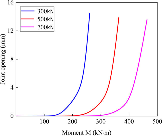
Joint opening
The variation rule of the maximum joint opening of the joint with the bending moment under different jacking forces is shown in Fig. 18. As shown in the figure, the maximum joint opening under different jacking forces shows a nonlinear change, and the opening process of the joint can be divided into three stages. In Stage 1, the joint opening remains constant as the bending moment increases, and the joint is nearly closed. At this point, the entire cross-section of the joint is under compression. The greater the jacking force is, the greater the bending moment at which the joint begins to open. In Stage 2, as the bending moment increases, the joint opening gradually increases, and the steel screw begins to exert force. The joint opening rate under different jacking forces is different, and the greater the jacking force is, the faster the joint opening rate. Stage 3, after the steel screw fails, the joint opening rate accelerates compared with that in the previous stage. Owing to the absence of a foundation, the joint opening rate is the same under different jacking force conditions, and the maximum joint opening is 14.47 mm. The study revealed that the greater the jacking force is, the longer the time in phase 1, the greater the bending moment when the joint begins to open, and the later the steel screw begins to be stressed.
Fig. 18.
Moment- maximum joint opening curve for different jacking forces.
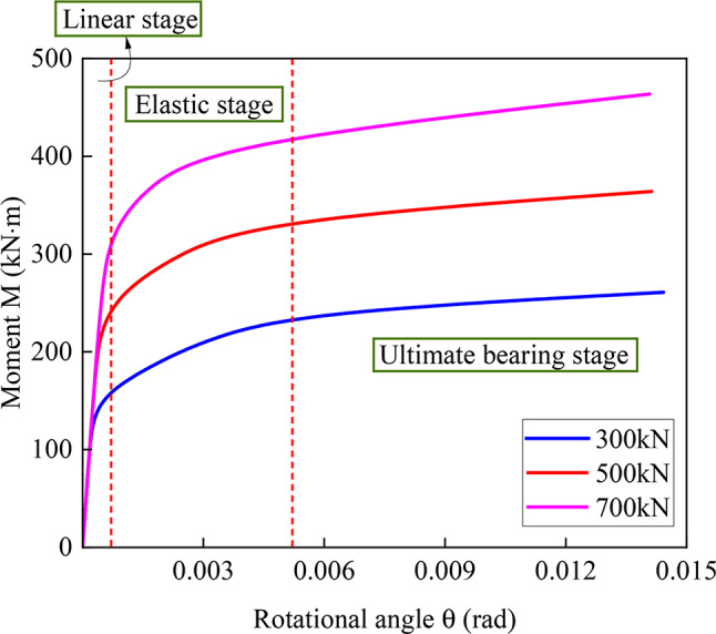
Joint rotation angle
The variation rule of the joint bending moment with respect to the rotation angle under different jacking forces is shown in Fig. 19. The figure shows that the bending moment‒rotation angle curve can be divided into three stages. In the linear stage, the joint bending moment and angle of rotation linearly develop, the maximum angle of rotation of the joint at this stage is 0.0007 rad, and the joint is in an approximately closed state. The larger the jacking force is, the larger the bending moment required when the joint starts to open. In the elastic stage, the joint starts to open, and the angle of rotation of the joint increases gradually with increasing bending moment. In the ultimate bearing stage, the angle of rotation of the joint increases further with increasing bending moment. The difference in the bending stiffness of the joint under different jacking forces is not significant. The larger the jacking force is, the larger the bending moment required to open the joint to the same angle of rotation. The above findings show that the jacking force has a certain restraining effect on the opening of the joint. Under the same bending moment, as the jacking force increases, the resistance of the joint to deformation increases, and the bending stiffness of the joint in the linear stage is maintained for a longer period. After the steel screw fails, the jacking force has no significant effect on the joint stiffness. However, the greater the jacking force is, the greater the load-bearing capacity of the joint for bending moments and the better the bending resistance of the joint.
Fig. 19.
Moment-rotation angle curve for different jacking forces.
Conclusions
By comparing the deformation and failure characteristics of steel screw joints with those of traditional F-type socket joints, the influence of the use of steel screw joints on the joints can be determined. The bending test of the joint under different coefficients of subgrade reaction is then carried out with the steel screw joint as the object, which compensates for the lack of research on the mechanical properties of the F-type socket joints of rectangular jacking pipes with steel screw connections. The influence of the jacking force on the bending performance of the joint during the construction process was further investigated via the finite element method. The main conclusions are as follows:
Compared with the traditional F-type socket joint, the contact between the steel ring and the concrete of the jack joint can be effectively retarded by arranging the steel screw at the axillary angle, which greatly reduces the risk of warping at the chamfer of the steel ring.
Joints connected by steel screws have greater stiffness and are more suitable for large-section tunnels. As the coefficient of subgrade reaction increases, the stiffness enhancement benefit of the steel screw to the joint decreases, and the closer the load carrying capacity of a steel screw connection joint is to that of a joint without a steel screw.
The damage to the joints is mainly concentrated in the jack joints, in which the damage to the joints without steel screw connections is mainly concentrated on the outside of the first step of the jack joints, which is manifested by the crushed concrete and covers the outside of the first step. The damage to the steel screw joint is more concentrated in the chamfered part.
Under the action of the jacking force, the bending deformation process of the joint can be divided into three stages: the linear stage, the elastic stage, and the ultimate bearing stage. The greater the jacking force is, the greater the ability of the joint to withstand bending moments and the better the bending resistance of the joint.
Acknowledgements
This work was supported by the National Natural Science Foundation of China (No. 52168060).
Author contributions
Y.X. and C.X. wrote the main manuscript text and C.Z. prepared fgures. All authors have reviewed the manuscript.
Data availability
The datasets used or analysed during the current study available from the corresponding author on reasonable request.
Declarations
Competing interests
The authors declare no competing interests.
Footnotes
Publisher’s note
Springer Nature remains neutral with regard to jurisdictional claims in published maps and institutional affiliations.
References
- 1.Ma, P. et al. Transition of the pipe jacking technology in Japan and investigation of its application status. Tunn. Undergr. Space Technol.139, 105212. 10.1016/j.tust.2023.105212 (2023). [Google Scholar]
- 2.Lu, H. F., Matthews, J. & Iseley, T. How does trenchless technology make pipeline construction greener? A comprehensive carbon footprint and energy consumption analysis. J. Clean. Prod.261, 121215. 10.1016/j.jclepro.2020.121215 (2020). [Google Scholar]
- 3.Cheng, W. C., Ni, J. C., Arulrajah, A. & Huang, H. W. A simple approach for characterising tunnel bore conditions based upon pipe-jacking data. Tunn. Undergr. Space Technol.71, 494–504. 10.1016/j.tust.2017.10.002 (2018). [Google Scholar]
- 4.Shi, P. X., Liu, W., Pan, J. L. & Yu, C. C. Experimental and analytical study of jacking load during microtunneling Gongbei tunnel pipe roof. J. Geotech. Geoenviron Eng.144(1), 05017006. 10.1061/(ASCE)GT.1943-5606.0001801 (2018). [Google Scholar]
- 5.Saiyar, M., Moore, I. D. & Take, W. A. Kinematics of jointed pipes and design estimates of joint rotationunder differential ground movement. Can. Geotech. J.52(11), 1714–1724. 10.1139/cgj-2014-0347 (2015). [Google Scholar]
- 6.Wu, D. P., Zhao, H. L. & Shen, H. C. Bending performance of the steel longitudinal joint for quasi-rectangular pipe-jacking tunnels. J. Pipeline Sys Eng.13(3), 04022026. 10.1061/(ASCE)PS.1949-1204.0000666 (2022). [Google Scholar]
- 7.Tang, J. & Li, S. C. Experimental study on the mechanical and deformation properties of pipe and soil inrectangular pipe jacking construction with controllable cement grouting technology. Staveb Obz Civ. En J.30(1). 10.14311/CEJ.2021.01.0011 (2021).
- 8.Liu, K. X. et al. Study on mechanical response of steel pipe jacking considering the effect of pipe sticking. Tunn. Undergr. Space Technol.127, 104617 (2022). [Google Scholar]
- 9.Zhang, P., Feng, X., Zeng, C. & Ariaratnam, S. T. Field performance of steel pipes during curve jacking in Gongbei tunnel. Tunn. Undergr. Space Technol.128, 104585 (2022). [Google Scholar]
- 10.Li, T. L., Zhao, W., Liu, R., Han, J. Y. & Cheng, C. Experimental study on the pipe-soil interface under the influence of pipe jacking stagnation time. Ksce J. Civ. Eng. ;1–11. (2021).
- 11.Liu, K. X. et al. Axial mechanical response of concrete pipe jacking considering the deflection of the bell-and-spigot joint: Full-scale test and numerical simulation. Tunn. Undergr. Space Technol.149, 105805 (2024). [Google Scholar]
- 12.Becerril García, D. & Moore, I. D. Behaviour of bell and spigot joints in buried reinforced concrete pipelines. Can. Geotech. J.52(5), 609–625. 10.1139/cgj-2013-0072 (2015). [Google Scholar]
- 13.Xu, Y. J. et al. Shear mechanical response and deformation failure of F-type socket joint in a rectangular pipe jacking tunnel under different geologic conditions. Sci. Rep.13 (1), 21967. 10.1038/s41598-023-49517-z (2023). [DOI] [PMC free article] [PubMed] [Google Scholar]
- 14.Wang, J. F., Wang, K., Zhang, T. & Wang, S. Key aspects of a DN4000 steel pipe jacking project in China: A case study of a water pipeline in the Shanghai Huangpu river. Tunn. Undergr. Space Technol.72, 323–332. 10.1016/j.tust.2017.12.012 (2018). [Google Scholar]
- 15.Wang, Y. C., Huang, J. H. & Luming, Y. Study on the Mechanical properties of large rectangular and shallow embedded Pipe-Jacking during pushing-Proces. Con Ser.358 (5), 052034. 10.1088/1755-1315/358/5/052034 (2019). [Google Scholar]
- 16.Jiang, X., Zhang, X. H., Wang, S., Bai, Y. & Huang, B. Case study of the largest concrete earth pressure balance pipe-jacking project in the world. Transp. Res. Rec. 2676 (7), 92–105. 10.1177/036119812210768 (2022). [Google Scholar]
- 17.Ma, P. et al. Investigation on the engineering effects of the geometrical configuration of the jacking rectangular pipe. Tunn. Undergr. Space Technol.119, 104239. 10.1016/j.tust.2021.104239 (2022). [Google Scholar]
- 18.Feng, X. et al. Joint bending stiffness and internal force calculation of assembled pipe jacking. Bull. Geol. Sci. Technol.40(02), 111–117. 10.19509/j.cnki.dzkq.2021.0019 (2021). [Google Scholar]
- 19.Wang, L. et al. Mechanical performance of a prefabricated subway station structure constructed by twin closely-spaced rectangular pipe-jacking boxes. Tunn. Undergr. Space Technol.13510.1016/j.tust.2023.105062 (2023).
- 20.Zhang, L., Kang, C., Liang, R. Z., Wu, B. S. & Li, Z. Longitudinal equivalent flexural stiffness of rectangular pipe-jacking tunnel in integrated pipe gallery. IOP Conf. Ser: Earth Environ. Sci.861(5). 10.1088/1755-1315/861/5/052107 (2021).
- 21.Xu, Y. J., Kang, J. W., Zhang, C., Pang, Y. K. & Huang, Z. D. Shear stiffness analysis of F-Socket joint in rectangular pipe jacking tunnel. China Railw Sci.45(02). 10.3969/j.issn.1001-4632.2024.02.11 (2024).
- 22.Ding, W. Q., Chen, X. Q., Jin, Y. L. & Qiao, Y. F. Flexural behavior of segmental joint containing double rows of bolts: Experiment and simulation. Tunn. Undergr. Space Technol.11210.1016/j.tust.2021.103940 (2021).
- 23.Xu, C. S., Han, R. B. & Du, X. Static pushover test technology and experimental study of spring-underground structure system considering soil-structure interaction. J. Build. Struct.44(01), 248–258. 10.14006/j.jzjgxb.2021.0571 (2023). [Google Scholar]
- 24.Xu, Y. J., Huang, Z. D., Zhang, C., Pang, Y. K. & Liu, T. Y. Bearing capacities and failure behaviors of F-type socket joint in rectangular pipe jacking tunnel. Appl. Sci.13(9). 10.3390/app13095442 (2023). [DOI] [PMC free article] [PubMed]
- 25.Xu, Y. J., Pang, Y. K., Zhang, C., Nie, X. Z. & Zhang, X. Experimental study on bending performance of an F-Type socket joint in rectangular pipe-jacking tunnels. Tunn. Constr.43(07), 1099–1110. 10.3969/j.issn.1001-4632.2024.02.11 (2023). [Google Scholar]
- 26.Code for design of concrete structures. China Archi-tecture and Building Press: (GB50010-2010), Beijing, (2010).
- 27.Technical specifcation for. Pipe Jacking Engineering with Rectangular Cross Section, China Archi-tectureand Building Press: (T/CECS 716–2020), Beijing, (2020).
Associated Data
This section collects any data citations, data availability statements, or supplementary materials included in this article.
Data Availability Statement
The datasets used or analysed during the current study available from the corresponding author on reasonable request.