

Abstract
The development of remediation technology for Per- and poly-fluoroalkyl substances (PFAS) has become one of the nation’s top research priorities as adverse impacts to environmental and human health have been increasingly identified. Of various water treatment routes, high-pressure membrane processes such as nanofiltration (NF) and reverse osmosis (RO) are considered most promising by virtue of the excellent rejection of both short- and long-chain PFAS and the proven technological maturity demonstrated with various water sources. Consequently, research activities have rapidly increased to accommodate research needs to advance NF and RO processes targeting PFAS removal from the aquatic environment. Therefore, the present review highlights recent findings in the areas of (a) rejection mechanism for PFAS, (b) the effects of membrane property and the water matrix, (c) challenges in high-recovery operation due to adsorption of PFAS and subsequent membrane fouling or scaling, and (d) complementary technologies to overcome the significant challenge to manage or treat a large volume of the waste stream from NF and RO. Overall, this review emphasizes research opportunities to develop engineering solutions that can be implemented in practical water treatment applications to address the imminent threat from PFAS.
Keywords: PFAS, Membrane, Water treatment, Reverse osmosis, Nanofiltration, Environment
1. Introduction
Per- and polyfluoroalkyl substances (PFAS), the high-performance chemicals developed since the 1940s, have found wide use in various industries, including waterproof fabrics, food wrappings, fire-resistant foams, and metal processing [1–5] for their strong resistance to heat, oil, stains, grease, and water. In recent decades, the rapid decline of PFAS production is attributed to growing concern about their potential health consequences such as hormone disruption, thyroid diseases, liver cancer, kidney failure, and immune toxicity [6–10]. Due to the evidence of the adverse health impacts, global regulatory agencies have mainly focused on two subgroups of nonpolymeric PFAS (Table 1): (1) perfluoroalkane sulfonic acids (PFSA), e.g., perfluorooctane sulfonate (PFOS) and perfluoroalkyl carboxylic acids (PFCA), e.g., per-fluorooctanoic acid (PFOA). Highly soluble in water, PFSA and PFCA can be easily transported through rivers and groundwater [11–15], potentially reaching humans via drinking water consumption. Consequently, it is estimated that over 200 million people in the U.S. are exposed to contaminated water at ≥ 1 ng/L PFOA and PFOS concentration [16] due to the widespread use of the chemicals and their exceptional persistence in the natural environment. To provide protection from exposure to PFOA and PFOS, U.S. Environmental Protection Agency (EPA) has established the lifetime health advisory (LHA) level at 70 ng/L for individual or combined concentrations of PFOA and PFOS in drinking water [17]. While restrictions on the production or import of longer carbon chain PFAS (i.e., > C6) with known health risks were implemented by government agencies, the industry has rapidly adopted to increase the use of alternative short-chain PFAS whose health impacts and toxicity remain largely unknown.
Table 1.
| Family | Classification | Molecular formula | Representative PFAS chemicals (carbon chain length) |
|---|---|---|---|
| Perfluoroalkyl substances | Perfluoroalkyl acids (PFAA) | CnF2n+1COOH (carboxylic acids; PFCA) | Perfluorobutanoic acid (C4) Perfluoropentanoic acid (C5) Perfluorohexanoic acid (C6) Perfluoroheptanoic acid (C7) Perfluorooctanoic acid (C8) Ammonium perfluorooctanoate (C8) Perfluorononanoic acid (C9) Perfluorodecanoic acid (C10) Perfluoroundecanoic acid (C11) Perfluorododecanoic acid (C12) Perfluorotridecanoic acid (C13) Perfluorotetradecanoic acid (C14) Perfluorohexadecanoic acid (C16) |
| CnF2n+1SO3H (sulfonic acids; PFSA) | Perfluorobutane sulfonic acid) (C4) Perfluoropentane sulfonic acid (C5) Perfluorohexane sulfonic acid (C6) Perfluoroheptane sulfonic acid(C7) Perfluorooctane sulfonic acid (C8) Perfluorononane sulfonic acid (C9) Perfluorodecane sulfonic acid (C10) |
||
| Perfluoroalkane sulfonamides (FASA) | CnF2n+1SO2NH2 | Perfluorooctane sulfonamide | |
| Polyfluoroalkyl substances | Fluorotelomer substances | CnF2n+1CH2CH2OH (alcohol) CnF2n+1CH2CH2SO3H (sulfonic acids) CnF2n+1CH2COOH (carboxylic acids) |
Fluorotelomer alcohol Fluorotelomer sulfonic acid Perfluorooctanoic acid Perfluorodecanoic acid |
| Perfluoroalkane sulfonamido substances | CnF2n+1SO2N(R’) aH (sulfonamides) CnF2n+1SO2N(R”) bCH2CH2 OH (sulfonamido ethanols) CnF2n+1SO2N(R”)CH2CO OH (sulfonamido acetic acids) |
N-methyl perfluorooctane sulfonamide N-ethyl perfluorooctane sulfonamide N-methyl perfluorooctane sulfonamido ethanol N-ethyl perfluorooctane sulfonamido ethanol N-methyl perfluorooctane sulfonamido acetic acid N-ethyl perfluorooctane sulfonamido acetic acid |
|
| Polyfluoroalkyl ether acids | The formula varies by substance (ether carboxylic acids) The formula varies by substance (ether sulfonic acids) |
Hexafluoropropylene oxide dimer acid 4,8-dioxa-3H-perfluorononanoic acid 9-chlorohexadecafluoro-3-oxanone-1-sulfonic acid Potassium 9-chlorohexadecafluoro-3-oxanonane-1-sulfonate |
R’ = CmH2m+1 where m = 1, 2, 4.
R” = CmH2m+1 where m = 0, 1, 2, 4.
Various water treatment technologies have increasingly been proposed [20] to address the potential risks [21] associated with prolonged exposure to PFAS in water sources. The most desirable water treatment approach for removal of PFAS may be chemical degradation technology (advanced oxidation/reduction via electrochemical [22,23], photocatalytic [24,25], or sonochemical [26,27] processes), as it may destroy PFAS to unharmful substances. However, slow reaction kinetics and water-matrix effects remain significant challenges to degradation [28], particularly when treating landfill leachate, a significant source of PFAS [12], and other high concentration and complex matrices. Not only the detrimental byproducts but also the high operating cost due to the enormous energy and chemical consumption remains a significant concern [29]. Sharma et al. [29] argue that the overall system efficacy can be improved by employing the combined (i.e., hybrid) systems composed of multiple water treatment technologies to overcome the above challenges.
Several commonly known water treatment technologies, including granular activated carbon (GAC), ion-exchange (IX), and membrane filtration, have been found effective for PFAS removal [13,30,31]. Given that adsorption is both a chemical and physical process occurring at the interface of the liquid solvent and the solid adsorbent, the performance of adsorption-based technologies (e.g., GAC, IX) depends on several factors including the material properties of adsorbent or the feed water constituents. For example, natural organic matter (NOM) in the feed stream may readily compete with PFAS molecules to occupy the adsorption sites, thereby reducing the rate of adsorptive removal of PFAS [5,32]. The limited effectiveness of GAC and IX for short-chain PFAS compounds due to the low adsorption capacity is of particular concern, as the industry has increasingly adopted short-chain PFAS to phase out longer-chain PFAS of environmental and health concerns [12,15,28,33,34]. In addition, when IX resins or GAC adsorbents are saturated or when the treatment goal is achieved, the media will need to be properly treated or managed (via landfill disposal, reactivation, or incineration) to avoid secondary contamination.
Of various membrane-based separation processes widely applied in water treatment industries, high-pressure membrane processes using nanoporous membranes such as nanofiltration (NF) and reverse osmosis (RO) have been found effective for separation of both short- and long-chain PFAS at excellent rejection efficiencies generally above 90% [13,30,31,35]. In high-pressure membrane processes, the pressurized feed stream enters the membrane’s feed channel, where selective permeation of water across the membrane occurs to produce the solutelean product water (the “permeate”). Coated over a supporting layer typically made of polysulfone or polyethersulfone, polyamide, a barrier layer of the membrane, shows excellent PFAS rejection in various water matrices [36]. PFAS molecules larger than the membrane pore size (e.g., present as colloidal particles, dissolved ions, etc.) are rejected by the barrier layer and ejected from the membrane element with the reject stream, i.e., the retentate (Fig. 1).
Fig. 1.

Cross-flow membrane filtration for the selective permeation of water across the asymmetric composite membrane made of a dense permselective skin and a microporous support layer where CF, Cm, and CP indicate the solute concentration of the bulk feed, the membrane surface, and the permeate, respectively, and ΔP and Δπ are the transmembrane pressure and the transmembrane osmotic pressure, respectively. Concentration polarization occurs as the solute concentration increases within the boundary layer developed above the membrane surface.
NF and RO processes employ cross-flow configuration to avoid the accumulation of solutes on the membrane surface that may require frequent system downtime to clean or replace the membrane elements. The water treatment capacity (i.e., the permeate productivity) and the system water recovery (defined as the volume of the permeate water produced per unit volume of the feed water) can be easily adjusted by the design of the membrane system [37,38]. Given the superior operational simplicity, flexibility and scalability, high-pressure membrane process is considered one of the most viable treatment technologies for PFAS separation from various types of feed water (e.g., groundwater, landfill leachate, seawater, etc.) both on– or offsite treatment applications [33,34,39,40]. Despite the above, NF and RO processes face the major limitation imposed by management or treatment challenges of the highly concentrated membrane waste. Accordingly, of particular interest to scientific and regulatory communities is the technology innovations to reduce post-treatment/management burdens by increasing water recovery.
The present review summarizes the performance of high-pressure membrane systems for the separation of PFAS from water. Recent efforts were introduced to fabricate membranes with enhanced performance based on the updated understanding of the interaction between PFAS and the membrane surface (e.g., PFAS adsorption or charge shielding). Additionally, operating characteristics in high-recovery operation (enabled by either multi-stage configuration or by recycling the membrane concentrate) were discussed to explain intrinsic challenges in high-pressure membrane processes such as high energy consumption or membrane fouling, magnified under high-recovery operating conditions. Lastly, the review introduces various complementary treatment technologies to overcome restrictions of individual technology to improve the overall treatment efficiency and meet the PFAS treatment goal.
2. PFAS separation using nanofiltration and reverse osmosis processes
2.1. Nanofiltration and reverse osmosis processes
NF and RO are pressure-driven filtration processes where the flux of the permeate across the membrane can be described by the following expression [41–43]:
| (1) |
where Lp is the water permeability, ΔP and Δπ are the applied pressure and the osmotic pressure differences across the membrane thickness, respectively. The reflection coefficient (σ) measures the selectivity of water passage relative to solute passage across the membrane [44], thereby approaching unity for the ideal membrane utterly impermeable to the solute. The applied pressure difference must remain higher than the osmotic pressure difference between the membrane feed and the permeate to maintain a positive permeate flux (i.e., to prevent the osmotic flow). This requires the continuous operation of hydraulic components (e.g., high-pressure pump). Tang et al. noted enhanced PFOS rejection under constant pressure potentially due to increased hydrodynamic permeate drag [45]. The above observation was more noticeable with membranes with high surface roughness due to the reduced hydrodynamic shear.
NF membranes are characterized by the pore size ranging between 1 and 10 nm, and show higher water permeability than RO membranes of pore size less than 1 nm [30,46]. Given that the separation of PFAS mainly achieved via size exclusion mechanism [31,47,48], the dense structure of RO membranes have shown higher observed rejection for PFAS, RS, which is defined in terms of the solute (e.g., PFAS) concentrations in the permeate (CP) and the feed stream (CF), respectively [41]:
| (2) |
In other words, the pore size of the permselective layer of the membrane dictates the membrane’s PFAS retention performance primarily via the steric (size) exclusion [48,49]. An earlier study by Tang et al. demonstrated the feasibility of RO and NF to treat semiconductor wastewater highly contaminated with PFOS over a wide range of concentrations 0.5–1500 ppm [31]. Steinle-Darling et al. further evaluated 15 different PFAS of different molecular weights and functional groups to reaffirm excellent rejections (>95%) by four commercial nanofiltrations and reverse osmosis membranes for anionic species for molecular weight above 300 g/mol [50]. The benefit of membrane processes was also shown in a study by Appleman et al. where full-scale water treatment systems throughout the U.S. using RO, GAC, and AIX technologies were compared for 16 different PFAS [13]. The study demonstrated that RO technology was capable of reducing PFAS below the method reporting limits (MRLs) while achieving stable productivity at high water recovery (>80%) [13]. The effectiveness of membrane processes was reaffirmed with >99% removal efficiencies for PFOA and PFOS in different stages of a drinking water treatment plant [35]. More recently, Liu et al. additionally reported rejections of 42 PFAS increasingly detected in the aqueous film-forming foam (AFFF) using flat sheet membrane systems [51]. The study confirmed that NF and RO membranes provide excellent (>97%) of most PFAS derived from AFFF water sources. However, it was noted that the rejection of short-chain PFAS with the sulfonate headgroup is prone to be affected by the water constituents such as dissolved organic matter (DOM) or Ca2+ to exhibit reduced rejection of 92–95%.
Due to the selective permeation of the water molecules, the concentration of PFAS at the membrane surface is relatively higher than that of the bulk feed stream (Fig. 1). The above phenomenon is known as concentration polarization (CP). Hang et al. reported that the severe CP effect may be caused by higher permeate flux, causing accumulation of PFOA molecules near the membrane surface [52]. In a recent study, Soriano et al. verified that NF membranes are prone to the CP effect relative to RO membranes, particularly when the PFAS concentration is low, to cause a significant decrease of the observed rejection [53]. Due to the accumulation of the solutes on the membrane, the surface concentration increases, causing a higher concentration gradient across the permselective layer of the membrane to promote transport of PFAS via diffusion, as demonstrated by Soriano et al. [54]. The solute transport across the NF and RO membranes are generally expressed by the classical solution-diffusion Kedem–Katchalsky model [55] as the addition of diffusional and convectional transport:
| (3) |
in which JS is solute flux, B is the solute permeability, Cm and CP are the solute concentrations at the membrane surface and in the permeate, respectively. Given that the size, shape, and functional group can largely vary for different PFAS, the contribution from each transport mechanism may also be different for a given membrane media and can be determined by a macroscopic approximation based on the flux and PFAS concentration measurements [43,55].
2.2. PFAS adsorption and charge shielding
Studies suggest that the charge-shielding effect causes electrostatic repulsion between PFAS and the membrane surface to reduce the level of CP and hence lower Cm [56,57]. However, co-existing cations such as Ca2+ or Na+ may negate the charge-shielding effect as they may associate with multiple PFAS molecules (causing PFAS charge neutralization), increasing the affinity for the membrane surface (Fig. 2). Soriano et al. compared the performance of commercial NF and RO membranes for the treatment of industrial wastewater highly concentrated with perfluorohexanoic acid (PFHxA) at 100 mg/L and experimentally verified the effect of the ionic strength of the feed solution, which weakened the electrostatic repulsion and reduced observed rejection at higher ionic strength [58]. It is important to note that the charge-shielding effect may not be significant at pH lower than the isoelectric point of the membrane as the surface may no longer be negatively charged [50]. The above studies also recognized the trade-off between the PFAS rejection and water permeability potentially due to adsorption promoted by the charge neutralization or low pH.
Fig. 2.

Electrostatic repulsion between PFOA and negatively charged membrane surface and charge neutralization of PFAS with metallic cations (e.g., Ca2+, Mg2+) cancel the charge-shielding effect.
Adsorption of PFAS (or other constituents) may reduce the active surface area for water permeation leading to the flux decline of the permeate [59]. PFAS adsorption within the membrane matrix and onto the membrane surface is a slow process [60], where it might be neglected over laboratory time scales. A recent study affirms negligible impact on rejection despite the observed adsorption of PFAS [51]. Bridging interactions between PFAS with other feed water constituents (e.g., Ca2+ or Mg2+) may increase the size of the PFAS complex, thereby increasing the PFAS rejection given the sieving mechanism [61]. Wang et al. used a hollow fiber NF membrane, made of poly (m-phenylene isophthalamide), and reported 2.5 fold increase in the average membrane roughness (3.67 to 9.79 nm) when 5-times more PFOS adsorption occurred in the presence of 2 mM Ca2+ due to charge-neutralization [62]. A noticeable decline in the permeate flux and the increase in PFAS rejection from 97.1% to 99.4% indicate improved rejection via size-exclusion mechanism due to pore blockage caused by PFAS adsorption. Kwon et al. noted that the PFAS with longer carbon chain are less prone to the charge-shielding effect. Adsorption may gradually cause pore-blockage to require higher hydraulic energy demand to maintain the permeate flux [12,14,39,45].
Given that the development of organic foulant may affect the membrane surface topology, PFAS adsorption can also be characterized by evaluating the surface roughness [63]. By examining the surface roughness on a commercial NF membrane using the images of SEM and AFM, Zhao et al. showed that cations in the feed solution (e.g., Ca2+) neutralize PFOS molecules, promoting the adsorption process [59]. Liu et al. attempted to quantify PFAS adsorption by observing the decreasing trend of the PFAS concentration over 13-day batch recirculation system with and without the membrane [51]. The study reports significant adsorptive losses of up to 20% particularly for hydrophobic PFAS such as PFOS and perfluoroheptanesulfonic acid (PFHpS). However, the study also noted that permeate and feed spacer consisting of the membrane element also acted as adsorption sites and may have increased the magnitude of the adsorptive loss observed from the study.
2.3. Modified membrane for PFAS separation
NF and RO can benefit from engineered permselective materials [64], providing the benefits of high PFAS rejection, reduced adsorption/fouling, and high water permeability in various feed matrices. Control over the rate of adsorption can be achieved by surface modification of the membrane. Kwon et al. revealed strong dependency of the PFAS adsorption on the properties of the active layer of the membrane. They demonstrated reduced PFAS adsorption onto the polyamide membrane surface by coating the active layer of the membrane with the aliphatic carbons and hydroxyl groups to limit interaction between PFAS and the membrane surface [60]. The study also shows that the adsorption behavior of PFAS is strongly correlated with the electrostatic interaction with the membrane surface. Boo et al. fabricated negatively charged polyamide NF membrane for enhanced PFOA selectivity by incorporating high molecular weight bipiperidine monomers via interfacial polymerization (Fig. 3a) [56]. Enhanced membrane performance was attributed to the enhanced electrostatic interaction of PFAS with the negatively charged membrane surface and tailored membrane pore size. The study also claims low scaling potential due to the high passage of mineral precursors (e.g., gypsum), which will significantly benefit the sustainable operations of high-recovery systems. A recent study by Huang et al. [65] also reported enhanced performance of NF membranes coated with a super-hydrophilic layer of polydopamine (PDA; Fig. 3b) for antiadhesion and antibacterial properties to prevent hydrophobic interaction between PFAS molecules and the membrane. The PDA coated NF membrane achieved a significant reduction in the transmission of PFOA by 20%. Still, studies have mainly focused on PFOA and PFOS, while shorter chain PFAS, e.g., Perfluorobutyrate (PFBA), which has increasingly substituted longer chain PFAS [66], are expected to become the major contributors to the total PFAS level in the drinking water [67]. Further investigation in the materials research is also needed in low-cost coating materials (e.g., cellulose acetate [68]) and long-term stability and physicochemical properties of the functionalized membranes.
Fig. 3.

Schematics of surface modified membranes for enhanced selectivity of PFAS using (a) a loose NF membrane of high surface charge for maximum charge shielding and water permeability prepared by interfacial polymerization of trimesoyl chloride and a mixture of piperazine and bipiperidine (Reprinted with permission from [56] (https://pubs.acs.org/doi/10.1021/acs.est.8b01040). Copyright 2018 American Chemical Society; further permissions related to the material excerpted should be directed to the ACS.), and (b) a hydrophilic membrane surface prepared by covalently bonded dense PDA layer over polyamide with microscopic analyses visualizing the variation of surface morphology and roughness as a result of the PDA surface coating (Reprinted with permission from [65]. Copyright 2021 Elsevier Ltd.)
2.4. High recovery operation
Despite the essential function of separation that NF/RO provides in water treatment, the generation of concentrate waste remains a lingering challenge, particularly when the membrane retentate contains PFAS, which may cause secondary contamination and invoke public concern. Only a fraction of the feed water is transferred to the permeate, and the remainder (i.e., the membrane retentate or the brine) is discharged from the membrane system as waste. Management or treatment of the membrane concentrate requires careful consideration to meet the quality criteria enforced by regulatory agencies and maintain the volume of the membrane concentrate waste below the daily treatment capacity of the post-treatment systems (e.g., sewer or septic systems). Therefore, it is desirable to maximize the water recovery, Y, (defined as Y = qP/qO, where qP and qO indicate the volumetric flow rate of the permeate and the raw-feed water, respectively; Fig. 4) to alleviate environmental concerns.
Fig. 4.
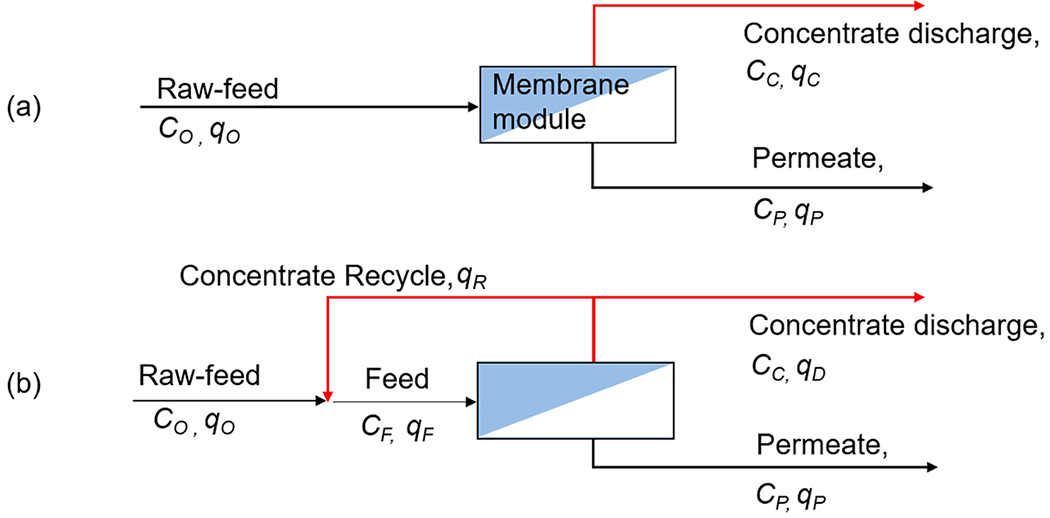
Schematic of simplified process flow in cross-flow membrane filtration with a single-stage membrane module operating (a) in a single pass, and (b) with concentrate recycling, where qO, qF, qP, qC, and qD and indicate the volumetric flow rates of the raw-feed, the feed, the permeate, the retentate, and the concentrate discharge, respectively, Co, CF, CC, and CP indicate the raw-feed, the feed, the retentate, and the permeate concentration of a contaminant, respectively.
Given the linear dependency of the volumetric flux of the permeate to the transmembrane pressure (Eq. (1)), water recovery can be increased by throttling the valve on the membrane concentrate. However, the recovery of commercial membrane elements is typically constrained to a low value (<15%) [50,60] to maintain the permeate flux specifications of the manufacturer [69,70]. Therefore, multiple stages of the reinforced pressure vessel house, each housing 4 – 6 membrane elements, can be configured in series to effectively increase the overall water recovery and the production capacity [71]. Multi-stage systems require high-capacity feed pumps and inter-stage booster pumps to overcome the loss of the hydraulic pressure of the membrane feed stream [72]. Accordingly, multi-stage membrane systems require a large system footprint to accommodate membrane and hydraulic components operating at stable (i.e., steady-state) conditions for optimum performance and efficiency.
An alternative approach to increase the water recovery is to adopt concentrate-recycling (Fig. 4b), where the membrane concentrate is mixed with the raw feed stream and reintroduced to the same membrane element [37,72], while the permeate is continuously collected as a product. In this approach, the membrane feed and the permeate flow rate can be maintained at a constant level, while the raw feed and the recycled concentrate streams can be adjusted simultaneously to meet the system recovery target (Fig. 5a). Concentrate recycling effectively increases the cross-flow velocity to reduce the thickness of the concentration boundary layer through which diffusive transport of solutes occurs towards the membrane surface, thereby reducing the CP effect. Concentrate recycling can be easily enabled with minimum retrofit to increase the overall water recovery of the membrane systems, including small-scale systems whose operating conditions may vary widely depending on the operating location or the season. However, high-recovery operation of the membrane system entails the higher concentration factor at the solution-membrane interface [70], which was shown to facilitate the formation of the membrane fouling, causing not only reduced permeate flux but also shortened life span of the membrane and higher energy demand (Fig. 5b) [37]. Gu et al. recently shared the results from the 2-year field study with their pilot-scale RO system, which had adopted total concentrate recycling condition (i.e., closed-circuit operation in which 100% of the membrane concentrate is being recycled). Closed-circuit RO (CCRO) operation is characterized by the rapid accumulation of the solutes in the feed channel [73]. Therefore, the “closed circuit mode” must be followed by the feed flushing to prevent or delay the onset of membrane fouling or mineral scaling [74]. Gu et al. demonstrated the use of CCRO to treat the RO concentrate to increase the overall water recovery from 84% to 91%. To adequately flush the CCRO system between the closed-circuit modes, the study adopted a blank pressure vessel known as the side conduit (SC) [75] to shorten operating time under stressed closed-circuit conditions. Despite the above, the author emphasized that triggering a concentrate purge mode will not be sufficient to prevent the membrane fouling or mineral scaling; therefore, process optimization is critical to determine the reasonable Clean-In-Place (CIP) interval.
Fig. 5.
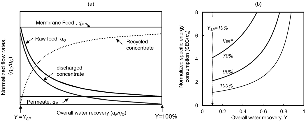
(a) Variation of the flow rates of each stream around the membrane module, normalized by the permeate flow rate (qP), with respect to the overall water recovery, Y (defined as Y = qP/qo) where YSP is the single pass water recovery (defined as YSP = qP/qF), and (b) specific energy consumption (SEC) normalized by the osmotic pressure of the raw feed stream (πO) in operation with concentrate recycling in high-pressure membrane processes at the various level the energy recovery efficiency (ηER) (reproduced with permission from [37]. Copyright 2019 Elsevier Ltd.).
CIP is an essential process to maintain the membrane’s integrity and performance to satisfy the concentrate discharge standards and maintain the product water quality. The economic analysis for the membrane system for PFAS treatment [76] estimates 15% of the overall operating cost is attributed to CIP process, which involves an injection of acid or base for chemical cleaning of the membrane. Operating strategies such as closed-circuit operation, backwashing, or feed-flow reversal (illustrated in Fig. 6), thus need to be considered as viable solutions to extend the CIP interval without a heavy dose of anti-fouling or anti-scaling agents.
Fig. 6.
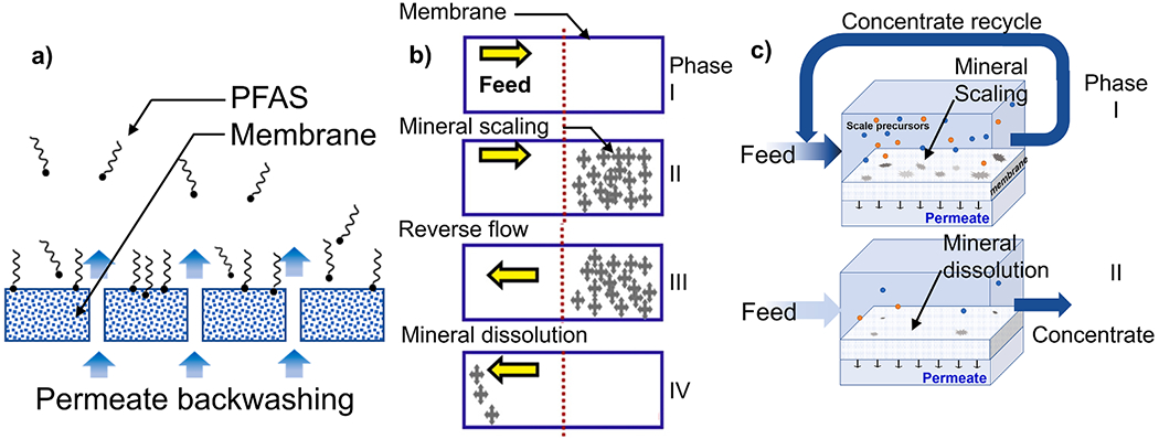
Schematics illustrating (a) permeate backwashing to desorbed PFAS molecules from the membrane surface, (b) periodic feed-flow reversal (FFR) to avoid the imbalanced development mineral scaling due to the axial concentration polarization (the direction of the feed flow is reversed in Phase III to allow the dissolution of the mineral; reproduced with permission from [77]. Copyright 2019 Elsevier), and (c) semibatch operation composed of two operating phases: (top) the closed-circuit phase and (bottom) the feed flushing phase, reproduced with permission from [70]. Copyright 2019, Elsevier.
3. Technologies complementary to NF and RO
Admittedly, continuous generation of a waste stream remains a major drawback; therefore, NF and RO processes may need to be coupled with other treatment technologies to overcome the trade-offs among water recovery, product water quality, and energy consumption. Verliefde et al. evaluated NF-GAC hybrid system whereby the permeate of the NF module is fed to a GAC unit for the treatment of surface water from the river to eliminate pharmaceutical compounds [57]. The study showed that the most substantial part of NOM was removed by the NF membrane, drastically improving the adsorption capacity of the GAC column. The study claims that a considerably prolonged theoretical lifetime of the GAC up to a factor of 100 [57,78] is viable with the utilization of NF as a pretreatment to GAC. The treatment of NF permeate with GAC for enhanced PFAS selectivity was later demonstrated in a pilot-scale field study by Tröger et al., reporting >75% improvements in treatment efficiency for PFAS using NF-GAC pilot system relative to full-scale Drinking water treatment plants (DWTP) in central Sweden [79]. However, the above study noted rapid deterioration of the treatment efficiency (from 75% to 35% on average for organic compounds) within the first 5 months of the operation, although effective service time of the NF-GAC system may depend on compounds fed to the system.
Franke et al. used groundwater contaminated with PFAS of MW 213–199 g•mol−1, and reported improved GAC performance with NF retentate than with the fresh raw feed water [47]. Interestingly, the PFAS removal efficiency of the GAC column was significantly higher when used for treating the NF retentate than for treating the raw feed water. Higher removal rates of GAC in NF-GAC system were attributed to additional sorption sites created by organic matters present in the membrane retentate. Additionally, desorption of PFAS from GAC was also observed when the adsorption column was fed by low concentrated raw feed water, causing negative removal efficiency over time [47]. The above study also compared the performance of NF-anion exchange (AIX) hybrid system with NF–GAC. The results demonstrated enhanced GAC and AIX performance with PFAS loading (g/volume of absorbent material) increases up to 2.6- and 4.1-fold in NF-GAC and NF-AIX, respectively, when they were combined with the NF. The author also noted a steep decrease in the AIX column’s removal efficiency to underperform relative to the GAC column eventually. In the latter study, Franke et al. used PHREEQC transport model [80] to investigate breakthrough patterns considering PFAS and water quality parameters and specified the concentration range of total PFAS where AIX or GAC is the most cost-effective solution for the membrane concentrate treatment. Provided the general understanding that PFAS breakthroughs can be delayed by increasing the adsorption capacity, studies have focused on developing materials of high sorption capacity. In a study by Murray et al., super-fine powder activated carbon (SPAC) showed > 480x greater adsorption capacity for quantifiable PFAS (e.g., PFBS, PFHxS, PFOS, PFOA, etc.) and twice higher adsorption potential than GAC [33]. Stebel et al. applied the sol-gel method to create expandable pores to accommodate polymer-infused organosilica, and showed up to x10 adsorption capacity for 12 short-chain and long-chain PFAS [81] to overcome low sorption potentials for short-chain PFAS. Studies revealed that that the control of PFAS in NF-GAC or NF-AIX mainly relies on the dose of GAC and AIX resin, filtration flux, adsorbent size, and PFAS properties. Accordingly, future research should optimize materials and processes to improve and adsorption capacity (defined as the weight of adsorbate per unit mass of the adsorbent). Detailed cost analysis needs to be followed when considering additional management or treatment requirements of the spent adsorbent (e.g., incineration, regeneration/reactivation, landfill disposal).
NF and RO processes can also be combined with degradation reactors to mineralize PFAS in the membrane retentate prior to further treatment or disposal to the environment. Boonya-atichart et al. evaluated the NF-Photocatalysis hybrid system, where the synthetic feed solution up to 100 μg·L−1 PFOA was treated by NF followed by the retentate treatment using photocatalysis degradation using zero-valent iron (nZVI) [82] via chemisorption of PFOA clusters on the positively charged surface of the catalyst [32]. The results showed PFOA removal from the NF retentate up to 59.6%, reducing the overall PFOA discharge by 34.2% from what it would be without incorporating the photocatalytic degradation [82].
Another example that coupled degradation and membrane processes was found from a bench-scale study conducted by Soriano et al., where bipolar boron-doped diamond (BDD) electrodes were adopted to achieve faster oxidation kinetics of PFHxA in the NF retentate [54]. The BDD electrode profoundly affects charge transfer due to strong electroactivity from the entire electrode surface [83,84]. Thus, the reaction constant of PFHxA electrochemical oxidation (ELOX) is substantially greater than previous studies using Ce-doped PbO2 [85]. Electrooxidation utilizes electron transfer between PFAS and the anode surface followed by hydroxylation and hydrolysis reactions progressively yielding shorter chained PFAS through reaction cycles until mineralization is completed. The study accomplished nearly complete degradation of PFHxA via ELOX at 50 A/m2 current density in the NF concentrate, achieving up to 99.4% removal (344 → 2 mg/L PFHxA). The downstream of the ELOX process was combined with the NF permeate, demonstrating zero liquid discharge (ZLD) concept (i.e., the overall water recovery, Y = 100%, and concentrate waste, qD = 0, Fig. 4) with the overall rejection at 89%. Additionally, the above approach required noticeably lower energy consumption of 15.2 kWh/m3 than previously reported values (41.7–76.6 kWh/m3) [85,86], validating commercial BDD cells’ application for full-scale PFAS treatment facilities. The BDD electrodes at a charge density of 100 and 20 A•m−2 required 0.9–4.4 h to achieve 90% defluorination of PFHxA in one batch cycle of the experiment in [54]. The trade-off between the energy consumption and conversion of PFAS in ELOX reaction remains a challenge, which requires further research endeavors. In a more recent study, Soriano et al. provided mathematical modeling for energy consumption and process optimization for cost analysis using the commercial modeling system (General Algebraic Modelling System, Fairfax, VA, USA) to determine the optimal process parameters (e.g., membrane and anode area, operating time, input and output concentrations, etc.) in NF-ELOX system [87]. The results suggest a large cost reduction (e.g., 88.2% for 4-log PFHxA abatement) for the NF-ELOX integrated system relative to ELOX treatment alone [87]. However, it is noted that the analysis is limited to ideal operating conditions (i.e., no residence time in ELOX reactor, perfect mixing, no membrane fouling, etc.); thus, it is difficult to justify the extent of the potential energy savings under the practical operating condition. Future work will need to address whether complete mineralization is achieved and any unintended consequences of blending back the water into the finished permeate water.
For the treatment of the membrane retentate at minimal addition of energy, direct-flow (i.e., dead end) filtration processes (Fig. 7b) may also be exploited. Guo et al. evaluated a gravity-driven direct-flow membrane filtration to remove PFOS using a highly porous nanofibrous membrane (coated on glass fibers) with high water-permeability of up to 355 LMH/kPa [88]. The study also demonstrated the successful regeneration of the membrane via methanol rinsing to maintain >85% removal efficiency of PFOS. The above results hint for the feasibility of using gravity-driven direct-flow filtration to treat the NF/RO retentate to enhance PFAS rejection and water recovery.
Fig. 7.
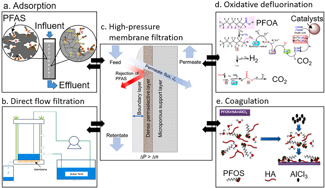
PFAS remediation via a combination of water treatment technologies for a synergistic effect: (a) adsorption process (e.g., GAC, AIX) (reproduced with permission from [89], respectively. Copyright 2019 Elsevier), (b) gravity-driven direct flow membrane filtration (reproduced with permission from [88]. Copyright 2016 Elsevier), (c) cross-flow membrane filtration, (d) the oxidative defluorination of PFOA (reproduced with permission from [24]), and (e) coagulation (reproduced with permission from [90], Copyright 2015 Elsevier).
Provided that PFAS are surfactants with a tendency to agglomerate, the combination of NF and coagulation can also be considered to improve PFAS rejection by promoting agglomeration of PFAS in the feed stream of the NF. Yu et al. evaluated the effectiveness of coagulation with aluminum chloride (AlCl3) to pretreat the NF feed stream by electrostatically bonding PFOS molecules to aluminum hydrolysate or floc [90]. The study demonstrated the effectiveness of coagulation-NF hybrid process with increased PFOS rejection from 55% to 86%.
In specific approaches of the aforementioned hybrid systems, a continuous process is established such that operating conditions are maintained constant, resulting in steady permeate productivity. Process parameters such as flow rates and operating pressure are more predictable in “time-invariant” processes, thereby providing operational simplicity. On the other hand, systems that may involve dynamic (time-dependent) operating parameters require sophisticated process control strategies. For example, the level of PFHxA in the reactor outlet is a direct function of the processing time in NF-ELOX hybrid system [54], given the pseudo-1st order electrochemical process of PFHxA [54]. In that study, the NF process was also a time-variant step (named “concentration mode”) as the level of PFHxA along with the total organic contents, TOC, and salts in the NF feed continuously increased (almost linearly for the high rejection membrane [73]) due to the recycling of the retentate to the feed tank.
During the concentration mode in closed-circuit of the NF-ELOX system study [54], the membrane module continuously produced permeate water at the same flow rate with the raw-feed entering the system (i.e., qP = qO, Fig. 4b), achieving 100% water recovery. The duration of the concentration mode may be limited based on the pressure limit of the physical membrane element (e.g., maximum operating pressure) or by the membrane fouling threshold. Large variation of the solute concentration along with corresponding osmotic pressure in the feed flow channel of the membrane during the closed circuit operation has been shown in a separate study with a saline feed water at 1000 mg/L TDS (Fig. 8b) [70]. The concentrated retentate stream produced from the NF concentration mode was then fed to the electrooxidation reactor, while the NF module was reconditioned with the fresh feed water for the next batch cycle (Fig. 8a). The amount of raw feed necessary for this reconditioning step (i.e., flushing) depends on the mixing characteristics in the membrane element and its impact on the fluid residence time [73,91,92]. It is noted that the closed-circuit operation of the high-pressure membrane system with periodic feed flushing may require higher energy consumption [73] and potentially show higher scaling potential [70] (relative to steady-state operation). It proves high process compatibility with other time-dependent water treatment methods (e.g., ELOX, GAC, IX) for potential use on a hybrid system in PFAS treatment. The development of time-variant NF/RO represents areas of current interest with the need to establish key parameters to optimize water recovery and rejection efficiency.
Fig. 8.
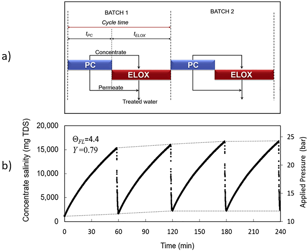
(a) Gantt-based chart for PC-ELOX (where PC stands for preconcentration step with the NF membrane unit) batch scheduling for NF-ELOX hybrid system (reproduced with permission from [87]. Copyright 2017 Elsevier), and (b) Variation of salinity (mg/L total dissolved solids, TDS) and the applied pressure (feed) during the closed-circuit operation at the overall water recovery, Y, of 79% with intermittent raw feed water flushing for the duration of n ΘFL = 4.4•tr (where tr is the system residence time). The experiment was conducted with RO membrane operating with the feed solution at 1000 mg/L TDS. (reproduced with permission from [73]. Copyright 2019 Elsevier).
4. Conclusions
This work provides summaries and reviews on the NF and RO technologies for PFAS separation from the aquatic environment. Many studies have proved the high rejection efficiency of NF and RO membranes for PFAS. However, there remains a challenge from generation of the membrane concentrate. Therefore, developing a high recovery membrane system is critical. In addition, continuous research efforts are needed not only to improve the selectivity for the vast number of PFAS molecules in various sizes, shapes, and properties, but also to prevent PFAS adsorption for sustainable operation of the system. In this regard, research opportunities lie in materials research utilizing the unique behaviors of PFAS molecules to control the interactions with the membrane surface or with other feed water constituents. Furthermore, future research needs to focus on design of treatment train to implement complementary technologies to overcome weaknesses of individual methods and achieve synergistic effects. NF and RO technologies underpin emerging treatment avenues for PFAS removal and warrant major contributions to future innovations in this area.
Acknowledgments
The U.S. Environmental Protection Agency reviewed and approved the work described here for publication. Note that approval does not signify that the contents necessarily reflect the views of the Agency. Mention of trade names, products, or services does not convey official EPA approval, endorsement, or recommendation.
Nomenclature
- AFFF
Aqueous film-forming foam
- AIX
Anion-exchange
- BDD
Boron-doped diamond
- DWTP
Drinking water treatment plants
- GAC
Granular Activated Carbon
- ELOX
Electrochemical oxidation
- IX
Ion-exchange
- MF
Microfiltration
- NF
Nanofiltration
- NOM
Natural organic matter
- PDA
Polydopamine
- PFAA
Perfluoroalkyl acids
- PFAS
Per- and polyfluoroalkyl substance
- PFBA
Perfluorobutyrate (PFBA)
- PFBS
Perfluorobutanesulfonic acid
- PFHpS
Perfluoroheptanesulfonic acid
- PFHxA
Perfluorohexanoic acid
- PFHxS
Perfluorohexanesulphonic acid
- PFOA
Perfluorooctanoic acid
- PFOS
Perfluorooctane sulfonic acid
- PFSA
Perfluoroalkane sulfonic acids
- RO
Reverse Osmosis SC Side-conduit
- SC
Side-conduit
- SEC
Specific energy consumption
- SPAC
Super-fine powder activated carbon
- ZVI
Zero-valent iron
Footnotes
Declaration of Competing Interest
The authors declare that competing financial interests or personal relationships, which may influence the present work, do not exist.
References
- [1].Xiao F, Emerging poly- and perfluoroalkyl substances in the aquatic environment: A review of current literature, Water Res. 124 (2017) 482–495, 10.1016/j.watres.2017.07.024. [DOI] [PubMed] [Google Scholar]
- [2].de Voogt P, Saez M, Analytical chemistry of perfluoroalkylated substances, Trac-Trend Anal Chem 25 (4) (2006) 326–342, 10.1016/j.trac.2005.10.008. [DOI] [Google Scholar]
- [3].Kissa E, Fluorinated Surfactants and Repellents, 2nd ed., Marcel Dekker Inc, New York, NY, 2001. [Google Scholar]
- [4].Prevedouros K, Cousins IT, Buck RC, Korzeniowski SH, Sources, fate and transport of perfluorocarboxylates, Environ. Sci. Technol 40 (1) (2006) 32–44, 10.1021/es051247510.1021/es0512475.s001. [DOI] [PubMed] [Google Scholar]
- [5].Crone BC, Speth TF, Wahman DG, Smith SJ, Abulikemu G, Kleiner EJ, Pressman JG, Occurrence of per- and polyfluoroalkyl substances (PFAS) in source water and their treatment in drinking water, Crit Rev Env Sci Tec 49 (24) (2019) 2359–2396, 10.1080/10643389.2019.1614848. [DOI] [PMC free article] [PubMed] [Google Scholar]
- [6].Bloom MS, Kannan K, Spliethoff HM, Tao L, Aldous KM, Vena JE, Exploratory assessment of perfluorinated compounds and human thyroid function, Physiol Behav 99 (2) (2010) 240–245, 10.1016/j.physbeh.2009.02.005. [DOI] [PubMed] [Google Scholar]
- [7].Jian JM, Guo Y, Zeng LX, Liu LY, Lu XW, Wang F, Zeng EY, Global distribution of perfluorochemicals (PFCs) in potential human exposure source-A review, Environ Int 108 (2017) 51–62, 10.1016/j.envint.2017.07.024. [DOI] [PubMed] [Google Scholar]
- [8].Dong GH, Tung KY, Tsai CH, Liu MM, Wang D, Liu W, Jin YH, Hsieh WS, Lee YL, Chen PC, Serum Polyfluoroalkyl Concentrations. Asthma Outcomes, and Immunological Markers in a Case-Control Study of Taiwanese Children, Environ Health Persp 121 (4) (2013) 507–513, 10.1289/ehp.1205351. [DOI] [PMC free article] [PubMed] [Google Scholar]
- [9].Lopez-Espinosa MJ, Fletcher T, Armstrong B, Genser B, Dhatariya K, Mondal D, Ducatman A, Leonardi G, Association of Perfluorooctanoic Acid (PFOA) and Perfluorooctane Sulfonate (PFOS) with Age of Puberty among Children Living near a Chemical Plant, Environ. Sci. Technol 45 (19) (2011) 8160–8166, 10.1021/es1038694. [DOI] [PubMed] [Google Scholar]
- [10].Wang IJ, Hsieh WS, Chen CY, Fletcher T, Lien GW, Chiang HL, Chiang CF, Wu TN, Chen PC, The effect of prenatal perfluorinated chemicals exposures on pediatric atopy, Environ Res 111 (6) (2011) 785–791, 10.1016/j.envres.2011.04.006. [DOI] [PubMed] [Google Scholar]
- [11].Boiteux V, Dauchy X, Bach C, Colin A, Hemard J, Sagres V, Rosin C, Munoz JF, Concentrations and patterns of perfluoroalkyl and polyfluoroalkyl substances in a river and three drinking water treatment plants near and far from a major production source, Sci. Total Environ 583 (2017) 393–400, 10.1016/j.scitotenv.2017.01.079. [DOI] [PubMed] [Google Scholar]
- [12].Wei ZS, Xu TY, Zhao DY, Treatment of per- and polyfluoroalkyl substances in landfill leachate: status, chemistry and prospects, Environ Sci-Wat Res 5 (11) (2019) 1814–1835, 10.1039/c9ew00645a. [DOI] [Google Scholar]
- [13].Appleman TD, Higgins CP, Quiñones O, Vanderford BJ, Kolstad C, Zeigler-Holady JC, Dickenson ERV, Treatment of poly- and perfluoroalkyl substances in U.S. full-scale water treatment systems, Water Res. 51 (2014) 246–255, 10.1016/j.watres.2013.10.067. [DOI] [PubMed] [Google Scholar]
- [14].Dharupaneedi SP, Nataraj SK, Nadagouda M, Reddy KR, Shukla SS, Aminabhavi TM, Membrane-based separation of potential emerging pollutants, Sep. Purif. Technol 210 (2019) 850–866, 10.1016/j.seppur.2018.09.003. [DOI] [PMC free article] [PubMed] [Google Scholar]
- [15].Rahman MF, Peldszus S, Anderson WB, Behaviour and fate of perfluoroalkyl and polyfluoroalkyl substances (PFASs) in drinking water treatment: A review, Water Res. 50 (2014) 318–340, 10.1016/j.watres.2013.10.045. [DOI] [PubMed] [Google Scholar]
- [16].Andrews DQ, Naidenko OV, Population-Wide Exposure to Per- and Polyfluoroalkyl Substances from Drinking Water in the United States, Environ. Sci. Technol. Lett 7 (12) (2020) 931–936, 10.1021/acs.estlett.0c0071310.1021/acs.estlett.0c00713.s00110.1021/acs.estlett.0c00713.s002. [DOI] [Google Scholar]
- [17].Hu XC, Andrews DQ, Lindstrom AB, Bruton TA, Schaider LA, Grandjean P, Lohmann R, Carignan CC, Blum A, Balan SA, Higgins CP, Sunderland EM, Detection of Poly- and Perfluoroalkyl Substances (PFASs) in U.S. Drinking Water Linked to Industrial Sites, Military Fire Training Areas, and Wastewater Treatment Plants, Environ. Sci. Technol. Lett 3 (10) (2016) 344–350. [DOI] [PMC free article] [PubMed] [Google Scholar]
- [18].Buck RC, Franklin J, Berger U, Conder JM, Cousins IT, de Voogt P, Jensen AA, Kannan K, Mabury SA, van Leeuwen SP, Perfluoroalkyl and polyfluoroalkyl substances in the environment: Terminology, classification, and origins, Integr. Environ. Assess. Manage 7 (4) (2011) 513–541, 10.1002/ieam.258. [DOI] [PMC free article] [PubMed] [Google Scholar]
- [19].U.S. EPA, Multi-Industry Per- and Polyfluoroalkyl Substances (PFAS) Study – 2021 Preliminary Report, in: Water O.o. (Ed.) 2021. [Google Scholar]
- [20].Tow EW, Ersan MS, Kum S, Lee T, Speth TF, Owen C, Bellona C, Nadagouda MN, Mikelonis AM, Westerhoff P, Mysore C, Frenkel VS, deSilva V, Walker WS, Safulko AK, Ladner DA, Managing and treating per- and polyfluoroalkyl substances (PFAS) in membrane concentrates, AWWA Water, Science 3 (5) (2021), e1233, 10.1002/aws2.1233. [DOI] [PMC free article] [PubMed] [Google Scholar]
- [21].Blake BE, Pinney SM, Hines EP, Fenton SE, Ferguson KK, Associations between longitudinal serum perfluoroalkyl substance (PFAS) levels and measures of thyroid hormone, kidney function, and body mass index in the Fernald Community Cohort, Environ. Pollut 242 (2018) 894–904, 10.1016/j.envpol.2018.07.042. [DOI] [PMC free article] [PubMed] [Google Scholar]
- [22].Le TXH, Haflich H, Shah AD, Chaplin BP, Energy-Efficient Electrochemical Oxidation of Perfluoroalkyl Substances Using a Ti4O7 Reactive Electrochemical Membrane Anode, Environ. Sci. Technol. Lett 6 (8) (2019) 504–510, 10.1021/acs.estlett.9b0039710.1021/acs.estlett.9b00397.s001. [DOI] [Google Scholar]
- [23].Pierpaoli M, Szopińska M, Wilk BK, Sobaszek M, Łuczkiewicz A, Bogdanowicz R, Fudala-Książek S, Electrochemical oxidation of PFOA and PFOS in landfill leachates at low and highly boron-doped diamond electrodes, J. Hazard. Mater 403 (2021), 123606, 10.1016/j.jhazmat.2020.123606. [DOI] [PubMed] [Google Scholar]
- [24].Verma S, Mezgebe B, Sahle-Demessie E, Nadagouda MN, Photooxidative decomposition and defluorination of perfluorooctanoic acid (PFOA) using an innovative technology of UV–vis/ZnxCu1 -xFe2O4/oxalic acid, Chemosphere 280 (2021), 130660, 10.1016/j.chemosphere.2021.130660. [DOI] [PMC free article] [PubMed] [Google Scholar]
- [25].Sahu SP, Qanbarzadeh M, Ateia M, Torkzadeh H, Maroli AS, Cates EL, Rapid Degradation and Mineralization of Perfluorooctanoic Acid by a New Petitjeanite Bi3O(OH)(PO4)2 Microparticle Ultraviolet Photocatalyst, Environ. Sci. Technol. Lett 5 (8) (2018) 533–538, 10.1021/acs.estlett.8b0039510.1021/acs.estlett.8b00395.s001. [DOI] [Google Scholar]
- [26].Gole VL, Sierra-Alvarez R, Peng H, Giesy JP, Deymier P, Keswani M, Sono-chemical treatment of per- and poly-fluoroalkyl compounds in aqueous film-forming foams by use of a large-scale multi-transducer dual-frequency based acoustic reactor, Ultrason. Sonochem 45 (2018) 213–222, 10.1016/j.ultsonch.2018.02.014. [DOI] [PubMed] [Google Scholar]
- [27].Phan Thi L-A, Do H-T, Lo S-L, Enhancing decomposition rate of perfluorooctanoic acid by carbonate radical assisted sonochemical treatment, Ultrason. Sonochem 21 (5) (2014) 1875–1880. [DOI] [PubMed] [Google Scholar]
- [28].Li F, Duan J, Tian S, Ji H, Zhu Y, Wei Z, Zhao D, Short-chain per- and polyfluoroalkyl substances in aquatic systems: Occurrence, impacts and treatment, Chem. Eng. J 380 (2020) 122506, 10.1016/j.cej.2019.122506. [DOI] [Google Scholar]
- [29].Sharma S, Shetti NP, Basu S, Nadagouda MN, Aminabhavi TM, Remediation of per- and polyfluoroalkyls (PFAS) via electrochemical methods, Chem. Eng. J 430 (2022), 132895, 10.1016/j.cej.2021.132895. [DOI] [Google Scholar]
- [30].Pramanik BK, Pramanik SK, Sarker DC, Suja F, Removal of emerging perfluorooctanoic acid and perfluorooctane sulfonate contaminants from lake water, Environ. Technol 38 (15) (2017) 1937–1942, 10.1080/09593330.2016.1240716. [DOI] [PubMed] [Google Scholar]
- [31].Tang CY, Fu QS, Robertson AP, Criddle CS, Leckie JO, Use of Reverse Osmosis Membranes to Remove Perfluorooctane Sulfonate (PFOS) from Semiconductor Wastewater, Environ. Sci. Technol 40 (23) (2006) 7343–7349, 10.1021/es060831q10.1021/es060831q.s001. [DOI] [PubMed] [Google Scholar]
- [32].Du Z, Deng S, Bei Y, Huang Q, Wang B, Huang J, Yu G, Adsorption behavior and mechanism of perfluorinated compounds on various adsorbents—A review, J. Hazard. Mater 274 (2014) 443–454, 10.1016/j.jhazmat.2014.04.038. [DOI] [PubMed] [Google Scholar]
- [33].Murray CC, Vatankhah H, McDonough CA, Nickerson A, Hedtke TT, Cath TY, Higgins CP, Bellona CL, Removal of per- and polyfluoroalkyl substances using super-fine powder activated carbon and ceramic membrane filtration, J. Hazard. Mater 366 (2019) 160–168, 10.1016/j.jhazmat.2018.11.050. [DOI] [PubMed] [Google Scholar]
- [34].Glover CM, Quinones O, Dickenson ERV, Removal of perfluoroalkyl and polyfluoroalkyl substances in potable reuse systems, Water Res. 144 (2018) 454–461, 10.1016/j.watres.2018.07.018. [DOI] [PubMed] [Google Scholar]
- [35].Flores C, Ventura F, Martin-Alonso J, Caixach J, Occurrence of perfluorooctane sulfonate (PFOS) and perfluorooctanoate (PFOA) in N.E. Spanish surface waters and their removal in a drinking water treatment plant that combines conventional and advanced treatments in parallel lines, Sci. Total Environ 461-462 (2013) 618–626. [DOI] [PubMed] [Google Scholar]
- [36].Toure H, Anwar Sadmani AHM, Nanofiltration of perfluorooctanoic acid and perfluorooctane sulfonic acid as a function of water matrix properties, Water Supply 19 (8) (2019) 2199–2205. [Google Scholar]
- [37].Lee T, Rahardianto A, Cohen Y, Flexible reverse osmosis (FLERO) desalination, Desalination 452 (2019) 123–131, 10.1016/j.desal.2018.10.022. [DOI] [Google Scholar]
- [38].Cohen Y, Rahardianto A, Lee T, System and Method for Flexible Low-Energy Membrane-based Liquid Purification, The Regents Of The University Of California, United States, 2020. [Google Scholar]
- [39].Arvaniti OS, Stasinakis AS, Review on the occurrence, fate and removal of perfluorinated compounds during wastewater treatment, Sci. Total Environ 524 (2015) 81–92, 10.1016/j.scitotenv.2015.04.023. [DOI] [PubMed] [Google Scholar]
- [40].Feng D, Song C, Mo W, Environmental, human health, and economic implications of landfill leachate treatment for per- and polyfluoroalkyl substance removal, J Environ Manage 289 (2021), 112558, 10.1016/j.jenvman.2021.112558. [DOI] [PubMed] [Google Scholar]
- [41].Mulder W, Basic Principles of Membrane Technology, 2nd ed., Kluwer Academic Publishers, Boston, 1997. [Google Scholar]
- [42].Zhu A, Christofides PD, Cohen Y, Effect of Thermodynamic Restriction on Energy Cost Optimization of RO Membrane Water Desalination, Ind. Eng. Chem. Res 48 (13) (2009) 6010–6021. [Google Scholar]
- [43].Kargol M, Kargol A, Investigation of reverse osmosis on the basis of the Kedem-Katchalsky equations and mechanistic transport equations, Desalination 190 (1-3) (2006) 267–276. [Google Scholar]
- [44].Spiegler KS, Kedem O, Thermodynamics of hyperfiltration (reverse osmosis): criteria for efficient membranes, Desalination 1 (4) (1966) 311–326, 10.1016/S0011-9164(00)80018-1. [DOI] [Google Scholar]
- [45].Tang CY, Fu QS, Criddle CS, Leckie JO, Effect of Flux (Transmembrane Pressure) and Membrane Properties on Fouling and Rejection of Reverse Osmosis and Nanofiltration Membranes Treating Perfluorooctane Sulfonate Containing Wastewater, Environ. Sci. Technol 41 (6) (2007) 2008–2014, 10.1021/es062052f10.1021/es062052f.s001. [DOI] [PubMed] [Google Scholar]
- [46].Kucharzyk KH, Darlington R, Benotti M, Deeb R, Hawley E, Novel treatment technologies for PFAS compounds: A critical review, J Environ Manage 204 (2017) 757–764, 10.1016/j.jenvman.2017.08.016. [DOI] [PubMed] [Google Scholar]
- [47].Franke V, McCleaf P, Lindegren K, Ahrens L, Efficient removal of per- and polyfluoroalkyl substances (PFASs) in drinking water treatment: nanofiltration combined with active carbon or anion exchange, Environ Sci-Wat Res 5 (11) (2019) 1836–1843, 10.1039/c9ew00286c. [DOI] [Google Scholar]
- [48].Banks D, Jun B-M, Heo J, Her N, Park CM, Yoon Y, Selected advanced water treatment technologies for perfluoroalkyl and polyfluoroalkyl substances: A review, Sep. Purif. Technol 231 (2020), 115929, 10.1016/j.seppur.2019.115929. [DOI] [Google Scholar]
- [49].Jin T, Peydayesh M, Mezzenga R, Membrane-based technologies for per- and poly-fluoroalkyl substances (PFASs) removal from water: Removal mechanisms, applications, challenges and perspectives, Environ Int 157 (2021), 106876, 10.1016/j.envint.2021.106876. [DOI] [PubMed] [Google Scholar]
- [50].Steinle-Darling E, Reinhard M, Nanofiltration for Trace Organic Contaminant Removal: Structure, Solution, and Membrane Fouling Effects on the Rejection of Perfluorochemicals, Environ. Sci. Technol 42 (14) (2008) 5292–5297, 10.1021/es703207s. [DOI] [PubMed] [Google Scholar]
- [51].Liu CJ, Strathmann TJ, Bellona C, Rejection of per- and polyfluoroalkyl substances (PFASs) in aqueous film-forming foam by high-pressure membranes, Water Res. 188 (2021), 116546, 10.1016/j.watres.2020.116546. [DOI] [PubMed] [Google Scholar]
- [52].Hang X, Chen X, Luo J, Cao W, Wan Y, Removal and recovery of perfluorooctanoate from wastewater by nanofiltration, Sep. Purif. Technol 145 (2015) 120–129, 10.1016/j.seppur.2015.03.013. [DOI] [Google Scholar]
- [53].Soriano A, Schaefer C, Urtiaga A, Enhanced treatment of perfluoroalkyl acids in groundwater by membrane separation and electrochemical oxidation, Chemical Engineering Journal Advances 4 (2020), 100042, 10.1016/j.ceja.2020.100042. [DOI] [Google Scholar]
- [54].Soriano A, Gorri D, Urtiaga A, Efficient treatment of perfluorohexanoic acid by nanofiltration followed by electrochemical degradation of the NF concentrate, Water Res. 112 (2017) 147–156, 10.1016/j.watres.2017.01.043. [DOI] [PubMed] [Google Scholar]
- [55].Kargol A, Modified Kedem-Katchalsky equations and their applications, J. Membr. Sci 174 (1) (2000) 43–53, 10.1016/S0376-7388(00)00367-7. [DOI] [Google Scholar]
- [56].Boo C, Wang Y, Zucker I, Choo Y, Osuji CO, Elimelech M, High Performance Nanofiltration Membrane for Effective Removal of Perfluoroalkyl Substances at High Water Recovery, Environ. Sci. Technol 52 (13) (2018) 7279–7288, 10.1021/acs.est.8b0104010.1021/acs.est.8b01040.s001. [DOI] [PubMed] [Google Scholar]
- [57].Verliefde ARD, Heijman SGJ, Cornelissen ER, Amy G, Van der Bruggen B, van Dijk JC, Influence of electrostatic interactions on the rejection with NF and assessment of the removal efficiency during NF/GAC treatment of pharmaceutically active compounds in surface water, Water Res. 41 (15) (2007) 3227–3240, 10.1016/j.watres.2007.05.022. [DOI] [PubMed] [Google Scholar]
- [58].Soriano Á, Gorri D, Urtiaga A, Selection of High Flux Membrane for the Effective Removal of Short-Chain Perfluorocarboxylic Acids, Ind Eng Chem Res 58 (8) (2019) 3329–3338, 10.1021/acs.iecr.8b0550610.1021/acsiecr.8b05506.s001. [DOI] [Google Scholar]
- [59].Zhao CW, Zhang J, He GZ, Wang T, Hou DY, Luan ZK, Perfluorooctane sulfonate removal by nanofiltration membrane the role of calcium ions, Chem. Eng. J 233 (2013) 224–232, 10.1016/j.cej.2013.08.027. [DOI] [Google Scholar]
- [60].Kwon Y-N, Shih K, Tang C, Leckie JO, Adsorption of perfluorinated compounds on thin-film composite polyamide membranes, J. Appl. Polym. Sci 124 (2) (2012) 1042–1049, 10.1002/app.35182. [DOI] [Google Scholar]
- [61].Zhao CW, Tang CY, Li P, Adrian P, Hu GS, Perfluorooctane sulfonate removal by nanofiltration membrane-the effect and interaction of magnesium ion/humic acid, J. Membr. Sci 503 (2016) 31–41, 10.1016/j.memsci.2015.12.049. [DOI] [Google Scholar]
- [62].Wang T, Zhao CW, Li P, Li Y, Wang J, Fabrication of novel poly(m-phenylene isophthalamide) hollow fiber nanofiltration membrane for effective removal of trace amount perfluorooctane sulfonate from water, J. Membr. Sci 477 (2015) 74–85, 10.1016/j.memsci.2014.12.038. [DOI] [Google Scholar]
- [63].Lin NH, Cohen Y, QCM study of mineral surface crystallization on aromatic polyamide membrane surfaces, J. Membr. Sci 379 (1–2) (2011) 426–433, 10.1016/j.memsci.2011.06.018. [DOI] [Google Scholar]
- [64].Nadagouda MN, Lee T, Cross-Flow Treatment of PFAS in Water: Materials Challenges and Potential Solutions, Accounts of Materials Research 2 (3) (2021) 129–133, 10.1021/accountsmr.0c00106. [DOI] [PMC free article] [PubMed] [Google Scholar]
- [65].Huang S, McDonald JA, Kuchel RP, Khan SJ, Leslie G, Tang CY, Mansouri J, Fane AG, Surface modification of nanofiltration membranes to improve the removal of organic micropollutants: Linking membrane characteristics to solute transmission, Water Res. 203 (2021), 117520, 10.1016/j.watres.2021.117520. [DOI] [PubMed] [Google Scholar]
- [66].Renner R, The long and the short of perfluorinated replacements, Environ. Sci. Technol 40 (1) (2006) 12–13, 10.1021/es062612a. [DOI] [PubMed] [Google Scholar]
- [67].Mastropietro TF, Bruno R, Pardo E, Armentano D, Reverse Osmosis and Nanofiltration membranes for highly efficient PFASs removal: overview, challenges and future perspectives, Dalton Trans. 50 (16) (2021) 5398–5410, 10.1039/D1DT00360G. [DOI] [PubMed] [Google Scholar]
- [68].Nataraj SK, Roy S, Patil MB, Nadagouda MN, Rudzinski WE, Aminabhavi TM, Cellulose acetate-coated alpha-alumina ceramic composite tubular membranes for wastewater treatment, Desalination 281 (2011) 348–353, 10.1016/j.desal.2011.08.016. [DOI] [Google Scholar]
- [69].Wang Y-N, Wang R, in: Membrane Separation Principles and Applications, Elsevier, 2019, pp. 1–45, 10.1016/B978-0-12-812815-2.00001-6. [DOI] [Google Scholar]
- [70].Lee T, Choi JY, Cohen Y, Gypsum scaling propensity in semi-batch RO (SBRO) and steady-state RO with partial recycle (SSRO-PR), J. Membr. Sci 588 (2019) 117106, 10.1016/j.memsci.2019.05.030. [DOI] [Google Scholar]
- [71].Ahunbay MG, Achieving high water recovery at low pressure in reverse osmosis processes for seawater desalination, Desalination 465 (2019) 58–68, 10.1016/j.desal.2019.04.023. [DOI] [Google Scholar]
- [72].Qiu T, Davies PA, Comparison of Configurations for High-Recovery Inland Desalination Systems, Water 4 (3) (2012) 690–706, 10.3390/w4030690. [DOI] [Google Scholar]
- [73].Lee T, Rahardianto A, Cohen Y, Multi-cycle operation of semi-batch reverse osmosis (SBRO) desalination, J. Membr. Sci 588 (2019), 117090, 10.1016/j.memsci.2019.05.015. [DOI] [Google Scholar]
- [74].Warsinger DM, Tow EW, Maswadeh LA, Connors GB, Swaminathan J, Lienhard JHV, Inorganic fouling mitigation by salinity cycling in batch reverse osmosis, Water Research 137 (2018) 384–394, 10.1016/j.watres.2018.01.060. [DOI] [PubMed] [Google Scholar]
- [75].Stover RL, Efraty N, Low-Energy Consumption With Closed-Circuit Desalination, IDA J. Desalin. Water Reuse 4 (3) (2012) 12–19, 10.1179/ida.2012.4.3.12. [DOI] [Google Scholar]
- [76].Franke V, Ullberg M, McCleaf P, Wålinder M, Köhler SJ, Ahrens L, The Price of Really Clean Water: Combining Nanofiltration with Granular Activated Carbon and Anion Exchange Resins for the Removal of Per- And Polyfluoralkyl Substances (PFASs) in Drinking Water Production, ACS ES&T Water 1 (4) (2021) 782–795, 10.1021/acsestwater.0c00141. [DOI] [Google Scholar]
- [77].Gu H, Bartman AR, Uchymiak M, Christofides PD, Cohen Y, Self-adaptive feed flow reversal operation of reverse osmosis desalination, Desalination 308 (2013) 63–72, 10.1016/j.desal.2012.07.041. [DOI] [Google Scholar]
- [78].Heijman SGJ, Hopman R, Activated carbon filtration in drinking water production: model prediction and new concepts, Colloids Surf., A 151 (1) (1999) 303–310, 10.1016/S0927-7757(98)00643-8. [DOI] [Google Scholar]
- [79].Troger R, Klockner P, Ahrens L, Wiberg K, Micropollutants in drinking water from source to tap – Method development and application of a multiresidue screening method, Sci. Total Environ 627 (2018) 1404–1432, 10.1016/j.scitotenv.2018.01.277. [DOI] [PubMed] [Google Scholar]
- [80].Sprocati R, Masi M, Muniruzzaman M, Rolle M, Modeling electrokinetic transport and biogeochemical reactions in porous media: A multidimensional Nernst–Planck–Poisson approach with PHREEQC coupling, Adv. Water Resour 127 (2019) 134–147, 10.1016/j.advwatres.2019.03.011. [DOI] [Google Scholar]
- [81].Stebel EK, Pike KA, Nguyen H, Hartmann HA, Klonowski MJ, Lawrence MG, Collins RM, Hefner CE, Edmiston PL, Absorption of short-chain to long-chain perfluoroalkyl substances using swellable organically modified silica, Environ. Sci. Water Res. Technol 5 (11) (2019) 1854–1866, 10.1039/C9EW00364A. [DOI] [Google Scholar]
- [82].Boonya-atichart A, Boontanon SK, Boontanon N, Study of hybrid membrane filtration and photocatalysis for removal of perfluorooctanoic acid (PFOA) in groundwater, Water Sci Technol 2017 (2) (2018) 561–569, 10.2166/wst.2018.178. [DOI] [PubMed] [Google Scholar]
- [83].Chaplin BP, Critical review of electrochemical advanced oxidation processes for water treatment applications, Environ. Sci. Processes Impacts 16 (6) (2014) 1182–1203, 10.1039/C3EM00679D. [DOI] [PubMed] [Google Scholar]
- [84].Patten HV, Lai SCS, Macpherson JV, Unwin PR, Active Sites for Outer-Sphere, Inner-Sphere, and Complex Multistage Electrochemical Reactions at Polycrystalline Boron-Doped Diamond Electrodes (pBDD) Revealed with Scanning Electrochemical Cell Microscopy (SECCM), Anal. Chem 84 (12) (2012) 5427–5432, 10.1021/ac3010555. [DOI] [PubMed] [Google Scholar]
- [85].Niu J, Lin H, Xu J, Wu H, Li Y, Electrochemical Mineralization of Perfluorocarboxylic Acids (PFCAs) by Ce-Doped Modified Porous Nanocrystalline PbO2 Film Electrode, Environ. Sci. Technol 46 (18) (2012) 10191–10198, 10.1021/es302148z. [DOI] [PubMed] [Google Scholar]
- [86].Zhuo Q, Deng S, Yang B, Huang J, Yu G, Efficient Electrochemical Oxidation of Perfluorooctanoate Using a Ti/SnO2-Sb-Bi Anode, Environ. Sci. Technol 45 (7) (2011) 2973–2979, 10.1021/es1024542. [DOI] [PubMed] [Google Scholar]
- [87].Soriano A, Gorri D, Biegler LT, Urtiaga A, An optimization model for the treatment of perfluorocarboxylic acids considering membrane preconcentration and BDD electrooxidation, Water Res. 164 (2019), 10.1016/j.watres.2019.114954. [DOI] [PubMed] [Google Scholar]
- [88].Guo H, Wang JQ, Han Y, Feng Y, Shih KM, Tang CY, Removal of perfluorooctane sulfonate by a gravity-driven membrance: Filtration performance and regeneration behavior, Sep. Purif. Technol 174 (2017) 136–144, 10.1016/j.seppur.2016.10.008. [DOI] [Google Scholar]
- [89].Gagliano E, Sgroi M, Falciglia PP, Vagliasindi FGA, Roccaro P, Removal of polyand perfluoroalkyl substances (PFAS) from water by adsorption: Role of PFAS chain length, effect of organic matter and challenges in adsorbent regeneration, Water Res. 171 (2020), 115381, 10.1016/j.watres.2019.115381. [DOI] [PubMed] [Google Scholar]
- [90].Yu Y, Zhao CW, Yu L, Li P, Wang T, Xu Y, Removal of perfluorooctane sulfonates from water by a hybrid coagulation-nanofiltration process, Chem. Eng. J 289 (2016) 7–16, 10.1016/j.cej.2015.12.048. [DOI] [Google Scholar]
- [91].Hasson D, Drak A, Komlos C, Yang Q, Semiat R, Detection of fouling on RO modules by residence time distribution analyses, Desalination 204 (1) (2007) 132–144, 10.1016/j.desal.2006.03.537. [DOI] [Google Scholar]
- [92].Yang Q, Drak A, Hasson D, Semiat R, RO module RTD analyses based on directly processing conductivity signals, J. Membr. Sci 306 (1) (2007) 355–364, 10.1016/j.memsci.2007.09.018. [DOI] [Google Scholar]