Abstract
The mechanical behavior and fracture mechanisms of deep fractured rocks under explosive dynamic loads are critical for understanding rock instability in engineering applications such as blasting operations. This study aims to investigate how the presence of pre-existing cracks and different stress states affect the mechanical properties and fracture patterns of rock-like specimens under dynamic loading conditions. We utilized a Split Hopkinson Pressure Bar (SHPB) with an active confining pressure loading device to conduct impact compression tests on rock-like specimens containing pre-existing cracks. These tests were performed under uniaxial and triaxial stress states to simulate various in-situ stress conditions. The study revealed three key findings: (1)The dynamic compressive strength of specimens with pre-existing cracks exhibited a non-monotonic relationship with crack inclination angle under uniaxial stress, contrasting with an increasing trend under confining pressure, highlighting the significant effects of confining pressure and strain rate. (2)Confining pressure significantly altered the failure modes, with specimens failing predominantly in axial tension at 0° and 90° crack inclinations, and a mix of axial tension and shear at 30° and 60°, indicating complex failure mechanisms. (3)The pre-existing crack angle under confining pressure influenced the propagation path and fractal dimension of the specimen, with an increasing angle correlating to higher fractal dimensions and a positive impact on compression peak stress. The research provides valuable insights into the complex fracture behavior of fractured rocks under dynamic loads, which can inform the design of blasting parameters in deep engineering. It also offers critical knowledge for preventing rock instability-related disasters, thus holding significant theoretical and practical importance in the field of rock mechanics and engineering.
Keywords: Deep rock mass, Explosive loading, Dynamic fracture, Crack inclination angle, Failure mode
Subject terms: Engineering, Civil engineering
Introduction
The 21st century has become a period during which human beings are actively engaged in the exploration and utilization of subterranean space. The international community has identified underground space as a potential area for growth in terms of land and resources. The number of projects aimed at the development of underground space is on the rise. These projects encompass a variety of areas, including mineral resource mining, hydropower construction, traffic tunnels, strategic energy reserves, and underground protection.
China has thus far constructed the largest number of tunnels and underground projects globally and is advancing toward deep rock masses1,2. Blasting excavation represents an indispensable component of the construction of water conservancy and hydropower projects, railways, municipal infrastructure, and other civil engineering projects.
Owing to its simplicity, flexibility, low cost, and strong applicability, blasting excavation is a widely employed technique in most tunnel construction in China3,4.
Due to the complex geological conditions, a large number of bedding and joint cracks frequently occur in the rock mass. When the smooth blasting technology is applied to tunnel excavation, parameters such as the number, spacing, and distribution of blast holes and the charge amount under corresponding lithological characteristics still lack systematic theoretical support, leading to severe overbreak and underbreak after tunnel excavation, and even tunnel collapse and other accidents5.
It can be observed that the rock’s mechanical properties play a vital role in determining the design parameters of deep rock blasting mining. However, the coupling effect of numerous micro-cracks in the rock and the in-situ stress environment of the deep rock makes the study on the deep rock under blasting impact complicated (Fig. 1).
Fig. 1.
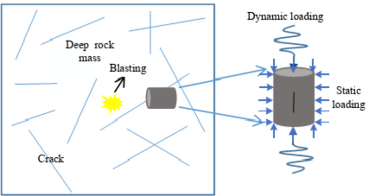
Deep rock mass with cracks subjected to dynamic loading.
At present, researchers have done a lot of research work on the effect of joint fractures on the rock mass under impact and the dynamic response characteristics of the rock mass under confining pressure. For example, X. Wu et al.6 conducted impact tests on concrete specimens containing five different inclined cracks using Split Hopkinson pressure bar (SHPB), and the damage forms of the specimens were studied in detail. H. Liu et al.7 used similar material modeling test methods to experimentally investigate the dynamic strength and damage modes under different nodal conditions with the help of a split Hopkinson pressure bar (SHPB) device. R. Yang et al.8 analyzed the effects of joint filling materials and different impact velocities on the dynamic mechanical properties of rock materials simulated by cement mortar by SHPB impact test. Z. Yan et al.9 used a modified SHPB system combined with high-speed photography and DIC monitoring to test multi-flawed rock specimens under coupled static-dynamic compression. It was systematically investigated the influences of pre-stress ratio, flaw inclination angle, and strain rate on the dynamic progressive cracking mechanism and energy evolution of multi-flawed rocks. L. Zhang et al.10 investigated the static-dynamic combined loading of composite parallel-fractured granite using the SHPB system and the non-contact monitoring device DIC. E. Liu et al.11 selected five groups of pre-cracked specimens with different pre-crack angles. The Brazilian splitting test was carried out by SHPB system.
In order to investigate the impact of rock joint parameters (joint spacing and joint dip angle, etc.) on rock failure effects, T. Liu et al.12studied the energy transmission laws of longitudinal waves incident at any angle to a set of nonlinear parallel joints13; preset joints at different angles in simulated materials and used uniaxial compression tests to explore the mechanical properties of jointed rock-like materials; H. Liu et al.14,15 employed similar material model testing methods, with the aid of a split Hopkinson pressure bar (SHPB) device, to conduct experimental studies on the dynamic strength and failure modes under different joint conditions; furthermore, J. Wang et al.14,16–19 analyzed the impact of joint dip angle, joint thickness, joint filling materials, and loading strain rate on the dynamic mechanical properties of rock materials simulated by cement mortar through SHPB impact tests.
To study the dynamic response of rocks under high loading rates, Samal, R.K. et al.20utilized two nonlinear strain rate-dependent constitutive models, namely the Johnson-Cook model and the Drucker-Prager model, to develop a three-dimensional finite element model of a split Hopkinson pressure bar setup with pre-cracked dog-bone specimens to understand crack behavior. Mishra, S. et al.21 reviewed the response of soils subjected to high strain rate loads. High strain rate loads on soils can be applied through high strain rate uniaxial compression tests, triaxial tests, split Hopkinson pressure bar (SHPB) tests, and shock tube tests, providing a comprehensive understanding of soil behavior under high load rates. In the study by Mishra, S. et al.22 on the stress-strain response of rocks under high loading rates, they conducted experiments on rocks of different sizes using the SHPB device and performed simulations and explosion analyses.
Aiming at the compound action of deep rock mass under high in-situ stress and explosion load, C. Lou et al.23 conducted a series of impact tests under triaxial static stress states corresponding to depths of 300–2400 m to reveal the dynamic mechanical characteristics of deep rocks. A. Zhang et al.24 analyzed the damage forms of marble at different uniaxial stress levels under different impact air pressures by means of an improved SHPB system and a high-speed monitoring system. X. Li et al.25 modified the SHPB apparatus and conducted an experimental study on the strength of siltstone samples under different coupled static and dynamic loads and observed that the strength of siltstone samples under coupled loads was higher than that under their corresponding individual static or dynamic strengths. Z. Yin et al.26 investigated the failure characteristics under coupled static and dynamic loading by the improved split Hopkinson pressure bar (SHPB) with axial pre-pressure and confining pressure. P. Kang et al.27 carried out longitudinal wave velocity measurements, uniaxial compression tests, and dynamic impact tests on granites from different burial depths to reveal the static and dynamic mechanical properties of the rocks.
The mechanical properties of rock with fissures under confining pressure and impact loading are currently difficult to study due to the limitations of experimental conditions. A review of the relevant literature from recent years reveals that W. You et al.28 performed a triaxial dynamic test on sandstone with single-angle defects under diverse radial contact pressures by employing an enhanced separated Hopkinson pressure bar (SHPB) system. Nevertheless, the dynamic properties and fracture characteristics of other angular fractured sandstones under impact remain ambiguous.
From the above, it is evident that existing research has extensively studied the dynamic fracture characteristics of rock under the influence of single factors, while there is less research on the dynamic fracture characteristics of rock under dynamic-static coupling. Under the action of different confining pressures, different forms of pre-existing cracks can lead to the deterioration of the physical and mechanical properties of rock masses, and the failure patterns can become complex. Especially in deep blasting operations, the combined action of high in situ stress and pre-existing cracks poses greater challenges and risks to construction. Therefore, this study utilizes a Split Hopkinson Pressure Bar (SHPB) impact device with active confining pressure to conduct impact loading tests on rock-like specimens with different crack inclination angles under various confining stress conditions. The study investigates the initiation modes of cracks, analyzes the strength and failure morphology of the specimens, thereby revealing the relationship between crack inclination angle, confining pressure, and failure patterns.
This study has made the following significant contributions to the field of rock mechanics and engineering: (1)Dynamic Fracture Characteristics Under Single Factors: We have provided an extensive review of the current understanding of the dynamic fracture characteristics of rock under the influence of single factors, highlighting the knowledge gaps that our research aims to address. (2)Dynamic-Static Coupling Effects: This research pioneeringly investigates the dynamic fracture characteristics of rock under dynamic-static coupling, an area that has been less studied compared to analyses under single factors. (3)Impact of Pre-Existing Cracks: We have explored how different forms of pre-existing cracks under various confining pressures can lead to the deterioration of the physical and mechanical properties of rock masses and complicate failure patterns. (4)Fracture Mechanism of Fractured Specimens: Our work focuses on elucidating the fracture mechanism of rock specimens with fissures under dynamic-static coupling, which is crucial for understanding the behavior of rock under complex stress conditions.
Experiments
Specimen preparation
(1) Materials and Molds.
A similar model test was adopted in this study, and the model test materials used to prepare rock-like specimens should meet the characteristics of “low strength, high brittleness and adjustable mechanical parameters” as far as possible. In line with the basic principle that raw materials should be widely available, low cost, and easy to process and mold29, ordinary silicate cement, model gypsum, fine sand, and water were selected as raw materials30, with specifications as shown in Table 1, and the ratio was determined to be cement: sand: gypsum = 1:6.47:0.76, and the ratio of water to the cement (cement + gypsum) was 0.6:1.
Table 1.
Raw materials for the test.
| Name | Cement | River sand | Gypsum | Water |
|---|---|---|---|---|
| Specification | P·O 52.5 Portland cement | 1.18 1.18 mm 1.18 mm |
Model plaster powder | Laboratory tap water |
The specimen size was  50 mm
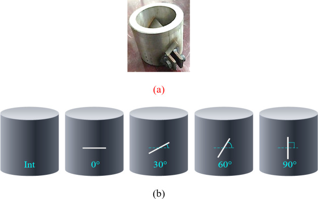
50 mm 50 mm, including two types of intact specimens and specimens with cracks, in which the intact specimens were made of standard molds with a diameter of 50 mm and a height of 50 mm(as shown in Fig. 2(a)). The fractured specimens were made of customized steel molds with a crack containing length of 20 mm, a thickness of 0.3 mm, and a pre-existing crack inclination angle (β) including 0
 , 30°, 60 °and 90°.
Fig. 2.
Mold for specimen preparation and rock-like specimens after demolding.
After the specimen was poured, it was placed in the standard concrete curing room for 24 h, then the iron sheet was pulled out and the mold was dismantled. The specimens after mold removal were shown in Fig. 2(b).
(2) Mechanical parameters of rock-like specimens.
Table 2 shows the physical and mechanical properties of rock-like specimens under static loading.
Table 2.
Basic physical and mechanical parameters of rock-like specimens.
| Density/g·cm−3 | Modulus of elasticity/GPa | Compressive strength/MPa | Tensile strength/MPa |
|---|---|---|---|
| 2.078 | 0.75 | 4 | 0.7 |
In general, the brittleness is used to represent the failure characteristics of rocks. In order to verify whether rock-like materials conform to the failure characteristics of natural rocks, brittleness index BI31 is introduced here:
 |
1 |
Where  is the static uniaxial compressive strength, and
  is the uniaxial tensile strength.
Testing apparatus
(1) SHPB system.
The experiment employs a ∅50 mm Split Hopkinson pressure bar (SHPB) impact device with an active confining pressure device (shown in Fig. 3), which consists of a loading system(shown in Fig. 4), an impact bar (bullet), an incident bar, a transmissive bar, a signal acquisition system, and a damping device.
Fig. 3.
Modified split Hopkinson pressure bar (SHPB) with radial confining system.
Fig. 4.
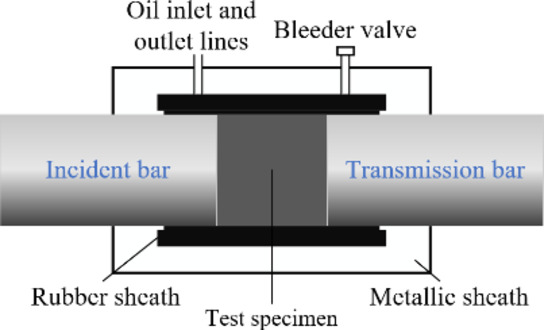
Sketch of active confining pressure device.
The length of impact bar is 0.60 m, and the length of incident bar and transmission bar are 2.40 m and 1.20 m, respectively. Each bar is made of alloy steel with a density of 7.8 g/cm3, a modulus of elasticity of 210 GPa, and a longitudinal wave speed of 5190 m/s. The voltage signal is collected by attaching 120-3AA resistance strain gauge to the incident bar and semiconductor strain gauge to the transmission bar respectively. The data signals were collected using a DPO3024 digital oscilloscope and a KD6009 strain amplifier.
For the loading scheme without confining pressure, before the impact test, adjust the SHPB test setup to align the centers of the incident bar and transmission bar with the specimen on the same horizontal line. Then, evenly apply Vaseline on both ends of the specimen to reduce the friction between the specimen and the bars before proceeding with the test. For the loading scheme with confining pressure, before the impact test, first adjust the SHPB test setup, then adjust the active confining pressure device to apply the required confining pressure, and finally align the centers of the incident bar and transmission bar with the specimen on the same horizontal line. Again, evenly apply Vaseline on both ends of the specimen to reduce the friction between the specimen and the bars before conducting the test.
Due to the low wave impedance of similar materials of cemented sand, semiconductor strain gauge technology was used to measure the weak transmitted signal, and the resistance strain gauge was still used on the incident bar. Paper31 was used as a waveform shaper to stick the end of the incident bar to improve the incident pulse load waveform and prolong the incident pulse load rise time.
(2) Data processing.
With the help of impulse signals generated by incident, reflected, and transmitted waves collected by strain gauges, the stress-strain relationship of the specimen can be obtained by processing the two-wave or three-wave method32 formulas (derived from the one-dimensional stress-wave theory) based on two basic assumptions. The specific formulas are shown below.
 |
2 |
 |
3 |
 |
4 |
Where  and
and  are the elastic rod wave velocity and elastic modulus, respectively, and the subscripts I, R, and T represent the incident, reflected, and transmitted waves, respectively.
  and
and  are the cross-sectional areas of the bar and the specimen respectively.
Loading scheme design
The prototype of this similar physical model test was the deep, extra-thick hard top plate of the Huainan Xinji Coal Mine33. The buried depth of the rock body is H = 1000 m, the bulk weight is  =26KN/m3, the horizontal lateral pressure coefficient of the in-situ stress is 1.5, and the similarity coefficient of the stress is
  =26.53. Since the strength of the original rock is 110 MPa, the strength of the required rock type is obtained to be 4.1 MPa. Also according to: vertical stress
 , get
, get  =26 MPa; average horizontal stress
  , get
, get  =39 MPa; average stress
  , get
, get  =32.5 MPa; simulated perimeter pressure value
 =1.23 MPa. Therefore, the design simulated confining pressure value
 =1.2 MPa.
The pre-test shows that the gas pressure settings of rock-like specimens under uniaxial impact compression are 0.15, 0.20 and 0.25 MPa respectively. When the specimens with cracks are loaded dynamically under confining pressure, the effects of confining pressure, crack angle and strain rate should be considered. After pre-testing, the impact pressures of the rock-like specimens were set at 0.4, 0.5 and 0.6 MPa respectively, and three parallel specimens were included under each impact pressure, as shown in Table 3.
Table 3.
Dynamic and static loading scheme.
| Loading method | Single-axis impact | Three-axis impact |
|---|---|---|
| Radial circumferential pressure/MPa | 0 | 1.2 |
| Axial impact air pressure/MPa | 0.15 | 0.4 |
| 0.20 | 0.5 | |
| 0.25 | 0.6 | |
| Number of specimens | 45 | 36 |
Results and analysis
Stress equilibrium analysis
In this study, the SHPB device was employed to conduct impact tests on the specimens. The two ends of the specimen can achieve stress balance before failure, which is a prerequisite for the one-dimensional stress wave assumption and the stress (strain) uniformity assumption34.
Figure 5 illustrates the equilibrium three-wave diagrams of the rock-like specimen subjected to impact. It can be observed that the sum of incident wave and reflected wave almost coincide with the transmitted wave curve, indicating that the specimen attains a state of stress equilibrium without considering the time lag.
Fig. 5.
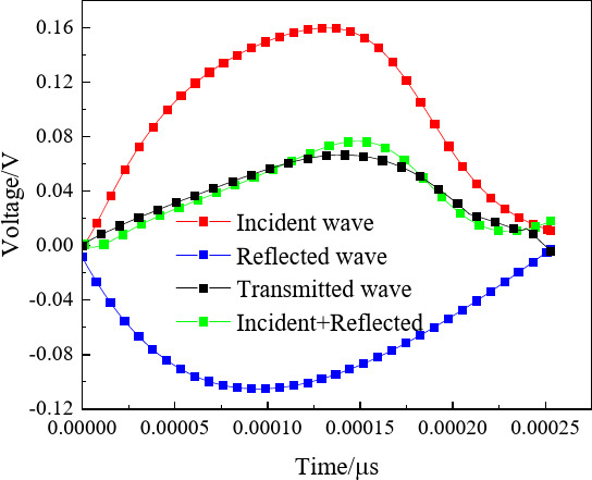
Three-wave diagram of stress balance.
Dynamic fracture characteristics of rock-like specimens under uniaxial impact
Stress-strain curve
It can be seen from Fig. 6 that for the uniaxial impact compression of rock-like specimens, the deformation and failure process is divided into three stages: elastic deformation section, plastic deformation stage (fracture stabilization-unstable expansion), yield stage, and failure unloading.
Fig. 6.
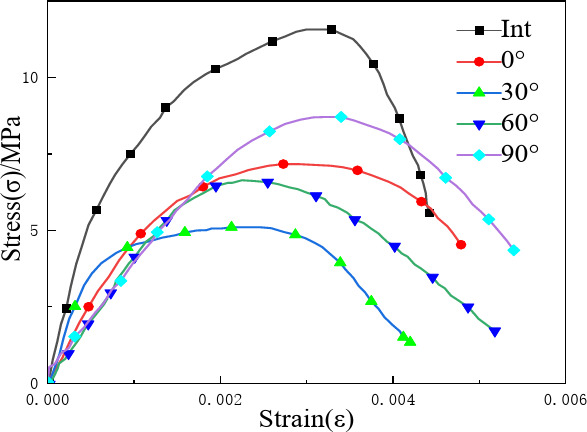
Stress-strain curves of specimens under uniaxial impact compression.
At the beginning, the specimen is subjected to load, resulting in elastic deformation, and the relationship between stress and strain is approximately linear. As the load continues to increase, micro-fractures emerge in the rock-like rocks, and stress concentrations are formed around pre-existed cracks. Cracks in the specimen grow steadily, the load further increases, the cracks propagate and intersect. At this time, the specimen is initially damaged and cracks enter the stage of unstable propagation. In the unloading stage, the crack at the end of preexisted crack extends to the upper and lower end faces of specimen, leading to the failure of specimen and the stress drop.
Under the condition of low impact pressure, the strengths of specimens with different crack angles are 11.56 MPa (intact), 7.16 MPa (0°), 5.10 MPa (30°), 6.63 MPa (60°), and 8.70 MPa (90°), respectively. The intact specimen has the highest strength, which is 2.27 times that of specimen with 30° inclination crack. Obviously, under uniaxial compressive load, the mechanical parameters such as peak stress and elastic modulus on stress-strain curve of intact specimen are significantly higher than those of the specimen with cracks, and the yield platform gradually decreases with the increase of crack Angle. It can be seen that different crack angles will lead to differences in the strength of specimen, and the mechanical properties of the specimen are closely related to its integrity and crack Angle. The crack will reduce the bearing capacity of the specimen, and with the increase of the crack Angle, its loading capacity will show a “V” -shaped change.
Compression failure patterns
The results of impact compression test on rock-like specimens with preexisted cracks demonstrate that the crack angle has a significant effect on the failure mode of the specimens. Consequently, uniaxial compression failure specimens under low strain rate loading were selected for dynamic failure mode analysis in this study.
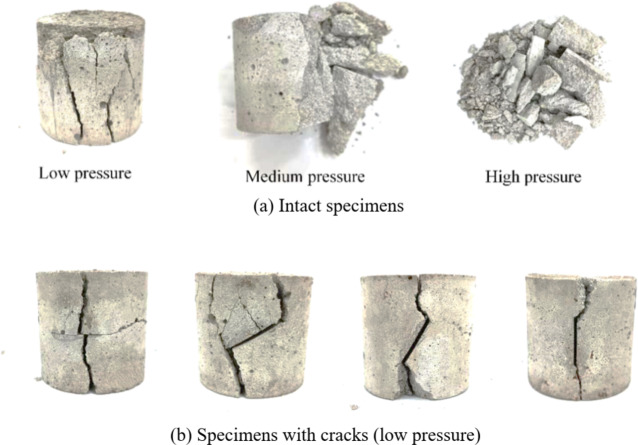
As shown in Fig. 7, the surface of the intact specimen shows shear-tension failure under the condition of medium and low impact pressure. With the condition of high impact pressure, the specimen has a high degree of fragmentation, but shear-tension failure is also the main failure mode. Due to the relatively high strength of intact specimen, the end of the specimen is the most severely damaged when it is impacted. Therefore, the failure starts from the end of specimen, extends in the direction parallel to the impact force, and finally breaks through the end of the specimen. At lower impact pressures, the specimen is spalling along with the block, and with the increase of the impact strain rate, the specimen is broken into blocks. Moreover, small fragments are mostly cone-shaped and relatively intact.
Fig. 7.
Impact failure diagram of specimens without confining pressure.
The failure modes of specimens with different preexisted cracks under impact load are dominated by wing cracks and secondary cracks, and the breakage of specimens is more obvious due to tensile shear forces.
Initiation Angle of specimen without confining pressure
The crack initiation Angle can reflect the crack propagation direction and predict the crack propagation path, which is the key factor in revealing the crack initiation mechanism. The Angle between the macroscopic initiation crack and the extension line of crack inclination is defined as the crack initiation Angle (α). As shown in Fig. 8, α1 is the crack initiation Angle of upper wing and α2 is the crack initiation Angle of lower wing.
Fig. 8.
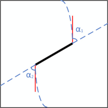
The diagram for crack initiation Angle in specimen.
According to the fractured morphology of specimens shown in Fig. 7, cracks are generated at the tips of the preexisted cracks. Therefore, the crack distribution diagram could be obtained based on this fractured morphology, where IMAGE J software was used to binarize the specimen for crack extraction. Finally, the crack distribution and propagation diagram of the fractured rock-like specimens with different inclination angles was obtained as shown in Fig. 9.
Fig. 9.
Schematic diagram of crack distribution and propagation after binarization.
Based on the Griffith strength criterion, it can be seen that the crack initiation position of the specimen after impact compression (as shown in Fig. 9) is predominantly concentrated in the stress concentration zone at the tip of the pre-existing crack, and the main crack initiation and further propagation occur along the tip of the pre-existing crack.
Further, the crack initiation angle was measured using IMAGE J according to Fig. 9, and the measured crack initiation angles of the upper and lower wings (α1, α2) are shown in Table 4.
Table 4.
Crack initiation Angle of upper wing and lower wing.
| Pre-existing crack inclination angle (β)/° | 0 | 30 | 60 | 90 |
|---|---|---|---|---|
| Crack initiation angle of upper wing(α1)/° | 82.875 | 59.140 | 45.862 | 12.053 |
| Crack initiation angle of lower wing(α2)/° | 81.959 | 66.500 | 38.083 | 7.300 |
According to the data in the table above, it can be observed that the initiation angle of the upper and lower wings decreases simultaneously with the increase of the pre-existing crack Angle, and the initiation angle of the upper wing is similar to that of the lower wing.
When the pre-existing crack inclination angle of specimen is between 0° and 30°, the increase in pre-existing crack inclination angle has a greater impact on the upper wing initiation angle than on the lower wing initiation angle. When the pre-existing crack inclination angle of the specimen is within the range of 30° to 60°, the increase in pre-existing crack inclination angle has a more substantial effect on the crack angle of the lower wing than on that of the upper wing. When the pre-existing crack inclination angle of the specimen ranges from 60° to 90°, the increase in pre-existing crack inclination angle has a similar effect on the crack angles of the upper and lower wings.
According to Table 4, the relationship between the measured crack initiation angles of the upper and lower wings (α1 and α2) and the pre-existing crack Angle (β) is drawn, as shown in Fig. 10.
Fig. 10.
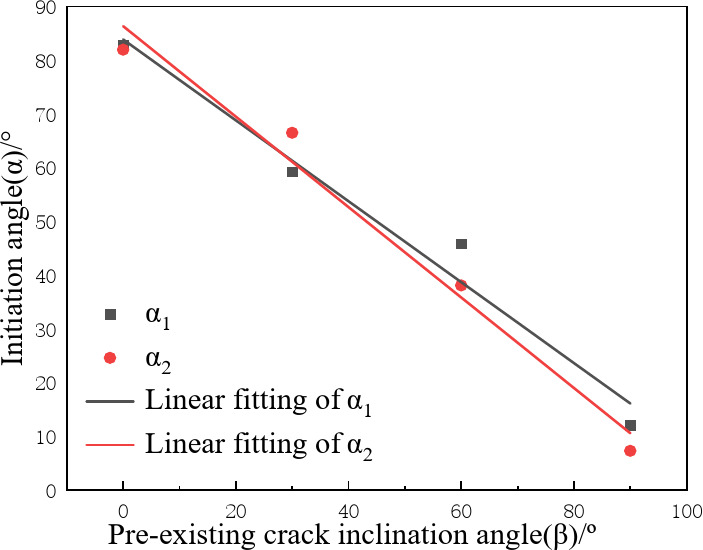
Relationship between crack initiation angle and pre-existing cracks inclination angle.
According to the relationship between crack initiation Angle and inclination Angle of pre-existing crack in Fig. 10, a linear function can be used to fit it to obtain the following relationship.
 |
5 |
 |
6 |
Where α represents the initiation angle, and β represents the pre-existing crack inclination angle.
In formula (5) and (6), the correlation coefficients (R2) are all greater than 0.95, indicating that there is a good linear relationship between the crack initiation Angle of specimen and its pre-existing crack inclination Angle.
According to the slope of the fitting relation between the crack initiation Angle of upper and lower wings and the inclination Angle of pre-existing crack, it can be seen that the pre-existing crack inclination Angle of specimen has different sensitivity to the upper and lower wing initiation angles, that is, the sensitivity to the lower wing initiation angle is greater than its sensitivity to the upper wing initiation angle.
Crack propagation mode of specimens without confining pressure
According to the criterion of maximum circumferential stress35–37, the expression for the stress field at the crack tip is:
 |
7 |
 |
8 |
 |
9 |
Where σr, σα and τr are the radial stress, tangential stress and shear stress of micro-element at the tip of pre-existing crack, respectively; α is the initiation Angle; KI and KII are the stress intensity factors of type I and type II cracks, respectively; r is the distance from micro-element to crack tip.
Based on the theory of stress intensity factor, the relationship of stress intensity factor for crack propagation at the crack tip of rock-like specimens can be expressed as:
 |
10 |
Where α is the initiation Angle; KI and KII are the stress intensity factors of type I and type II cracks, respectively.
For type I cracks, let KI not be 0 and KII be 0, and obtain the crack initiation Angle α is 0 or π. For the specimen with pre-existing crack inclination angle of 90°, the actual crack initiation Angle is 9.67°, which is close to the theoretical calculation value. Therefore, it can be considered that the failure of this specimen belongs to type I crack.
For type II cracks, let KI be 0 and KII be  , and obtain the crack initiation Angle α is 70.53°. For the specimen with pre-existing crack inclination angle of 0°, the actual crack initiation Angle is 82.417°, which is close to the theoretical calculation value. So, it can be considered that the failure of this specimen belongs to the type II crack.
When the pre-existing crack angles of specimens are 30° and 60°, the actual cracks initiation angle of specimens are respectively 62.82° and 41.913°, ranging from 0° to 70.53°, which indicates that the failure of this specimen at this time belongs to I-II composite crack cracking.
As shown in Fig. 11, the failure modes of specimens with different crack pre-existing angles are consistent with the above calculation results.
Fig. 11.
Failure modes of specimens with different crack inclination angles.
In summary, it can be concluded that the failure modes of rock-like specimens without confining pressure present three failure modes: tensile, shear, and combination of tensile and shear.
For specimens with cracks of different inclination angles, when the crack inclination Angle is 0°, the surface of specimen demonstrates shear failure. When the crack inclination Angle is between 30° and 60°, the specimen exhibits a combination of tensile and shear failure. In comparison to the specimens with 0° and 90° inclinations Angle cracks, the fracture degree of specimens with 30° and 60° inclinations Angle cracks is higher, and the fine cracks are densely distributed.
This is because when the crack inclination Angle is between 30° and 60°, the stress is concentrated at the crack tip, and the internal force of specimen is uneven, resulting in more obvious breakage of the specimen. The specimen with a 90° inclination angle crack is predominantly subjected to tensile failure, characterized by a tensile crack in the specimen accompanied by a minor amount of debris collapse.
Distortion energy of specimens without confining pressure
According to the distortion energy theory, the reason for the failure of materials under uniaxial compression is that the distortion at a certain point inside reaches the limit value under uniaxial stress38. The dimensionless distortion energy density can be calculated by Eq. (11):
 |
11 |
Where, β is the inclination Angle of prefabricated fracture; c11=φ+1 + φcosα-cos2α; c12 = sin2αφsinα; c22 =φ+4φ cosα3sin2α; φ=2 [(1µ)/(1 + µ)] 2/3; α is the initiation Angle; µ is the friction coefficient, which is 0.839.
Based on this, the dimensionless distortion energy density of specimens with cracks under uniaxial dynamic compression can be calculated when damage occurs, and the results are shown in Fig. 12. Concurrently, the impact compressive strength of specimens under a low strain rate is plotted in Fig. 12, and the relationship between dimensionless distortion energy density and impact compressive strength is established.
Fig. 12.
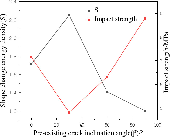
The variation of S and impact strength with pre-existing crack inclination angle (β).
As illustrated in the above figure, there is a negative correlation between the dimensionless distortion energy density and uniaxial compressive strength. With the increase of pre-existing crack inclination angle, the dimensionless distortion energy density initially increases and subsequently decreases, and the maximum and minimum values are obtained at 30° and 90° of pre-existing crack inclination angle, respectively. But the impact strength first decreases and then increases, and the maximum and minimum values are obtained at 90° and 30° of pre-existing crack inclination angle, respectively. These findings align with the research results of Q. Guo et al.40 Indicating that the results of this study are consistent with the distortion energy theory, that is, the larger the distortion energy is, the poorer the bearing capacity of the specimen under impact compression load.
Dynamic fracture characteristics of specimens with cracks under confining pressure
Stress-strain curve
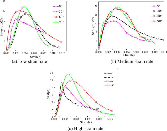
Under the confining pressure of 1.2 MPa, the dynamic deformation and failure of rock-like specimen have great changes. As shown in Fig. 13, the dynamic stress-strain curve of rock-like specimens under confining pressure can be divided into four stages: compaction stage, elastic deformation stage, crack propagation stage and failure unloading stage. Compared with the uniaxial impact compression curve, it has a clear compaction stage. Because under confining pressure constraints, the specimen is difficult to break, so the pores and cracks are preferentially compressed and closed. As the load gradually increases, cracks begin to propagate and extend. Due to the presence of confining pressure, the lateral deformation of specimen is constrained (i.e., axial cracks are restricted from propagating), so most of the cracks extend radially. Moreover, the curve quickly drops after reaching the peak stress, exhibiting typical brittle failure.
Fig. 13.
Stress-strain curves of specimens under triaxial impact compression.
Furthermore, the dynamic compressive strength of rock-like specimens is observed to increase in comparison to specimens without confining pressure, and the strength of specimens with the same crack inclination Angle demonstrates a gradual increase with the rise in strain rate, which has obvious confining pressure effect and strain rate effect. This is due to the fact that the impact process will result in the formation of cracks in the rock-like specimen, while the application of confining pressure will serve to inhibit the initiation and subsequent development of cracks. This is also the reason why the cracks observed in the main crack expansion zone of the specimen are significantly reduced in comparison to the condition in the absence of confining pressure. It is noteworthy that under the same strain rate, the dynamic compressive strength of rock-like specimens exhibits an increase with the increase of crack inclination angle, which is significantly different from the effect of crack inclination Angle on dynamic compressive strength under uniaxial impact compression. Consequently, the dynamic fracture mechanism of specimens with cracks under confining pressure will be discussed in Sect. 4.
Fracture morphological characteristics
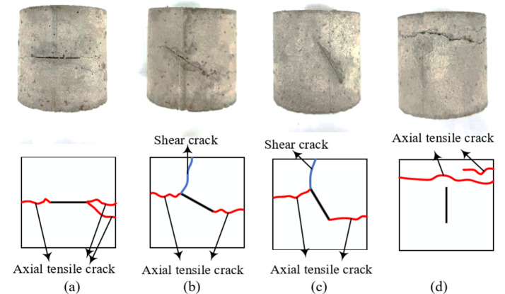
From the analysis results in Sect. 3.2.2 of this study, it can be concluded that the inclination angle of cracks has a significant impact on the dynamic failure mode of the specimens. Under the coupling effect of dynamic and static, the rock-like specimen with crack will also be subjected to the action of confining pressure static load, and its dynamic failure mode will inevitably change. Therefore, the triaxial compression fracture morphology of rock-like specimens under high strain rate loading was analyzed in this study, as shown in Fig. 14.
Fig. 14.
Crack propagation mode under confining pressure (impact pressure 0.6 MPa).
When the crack inclination Angle of rock-like specimen is 0° (Fig. 14a), 1–2 axial tensile cracks appear at the crack tip and extend laterally along the surface of specimen, which belongs to axial tensile failure. It can be seen from the analysis that during the axial compression stage of specimen, local high strain is concentrated in the middle of the pre-existing crack and tensile cracking occurs. However, in the loading direction, due to the restraining effect of confining pressure, the propagation of crack in this direction is limited, ultimately resulting in axial tensile failure.
When the crack inclination Angle of rock-like specimens is 30° (Fig. 14b), cracks including axial tensile cracks and shear cracks are generated on it, among which axial tensile cracks are the majority. The propagation of newly formed cracks also starts from crack tip, followed by tensile cracks and wing shaped cracks. The wing shaped cracks penetrate the top of specimen along the loading direction, ultimately forming a tensile shear composite failure.
When the crack inclination Angle of rock-like specimens is 60° (Fig. 14c), specimens also begin to fail at the crack tip, and eventually form a tension-shear composite failure mode, which tends to be consistent with the dynamic failure mode of specimens with cracks without confining pressure.
When the crack inclination Angle of rock-like specimens is 90° (Fig. 14d), the failure of the rock like specimen does not start along the crack tip, but multiple axial tensile cracks are generated at one end of the specimen (near the incident rod side). This indicates that the concentrated stress generated at the crack tip of pre-existing crack parallel to the axial direction is smaller than the confining stress, which restricts the crack to expand along the loading direction. As a result, no Type I failure occurred in the specimen. It can also be concluded that the confining pressure constraints cause great changes in the force on specimen, which makes it difficult for the specimen to produce tensile failure along the radial direction under the axial dynamic load, and cannot preferentially produce shear failure along the axial direction.
Fractal dimension of fracture
The fractal dimension Dis a measure of the irregularity of a complex shape, which reflects the effectiveness of the space occupied by it. Now the box-counting dimension method41 is used to calculate the fractal dimension D of crack growth of specimens. The basic idea of this algorithm is to first divide the image into small square boxes of equal size (the side length is r), then cover all areas of the image with boxes one by one (as shown in Fig. 15), and calculate the number of small square boxes N (r) required to cover the entire fractal structure. Then the size of the box side length (r) is changed, and the corresponding box number N (r) value is calculated. Finally, the box side length r and the box number N (r) are taken as the horizontal and vertical values of the data points, and each data point is fitted by a straight line.
Fig. 15.
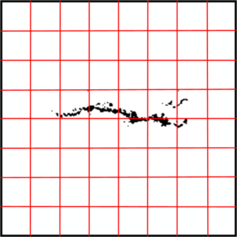
Box dimension method for specimens.
The slope of the line is the fractal dimension value of the research object, as shown in Eq. 1241,42.
 |
12 |
Where D represents the fractal dimension, N(r) represents the number of small square boxes needed to cover the entire fractal structure, and r represents the side length of the boxes.
The high-resolution IMAGE of the specimen captured by the camera was imported into IMAGE J software for image binarization processing, and the fractal dimension of the expanding crack was calculated. Figure 16 shows the calculation process of fractal dimension of crack development path for specimens with pre-existing crack inclination Angle of 90°.
Fig. 16.
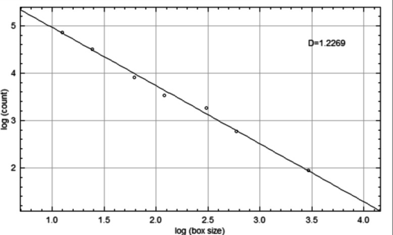
Fractal dimension for specimen with crack with crack inclination of 90° inclination of 90°.
Based on IMAGE J’s calculation on the fractal dimension of expansion crack of specimens with different crack inclination Angles, the relationship between fractal dimension and pre-existing crack inclination Angle is obtained, as shown in Fig. 17.
Fig. 17.
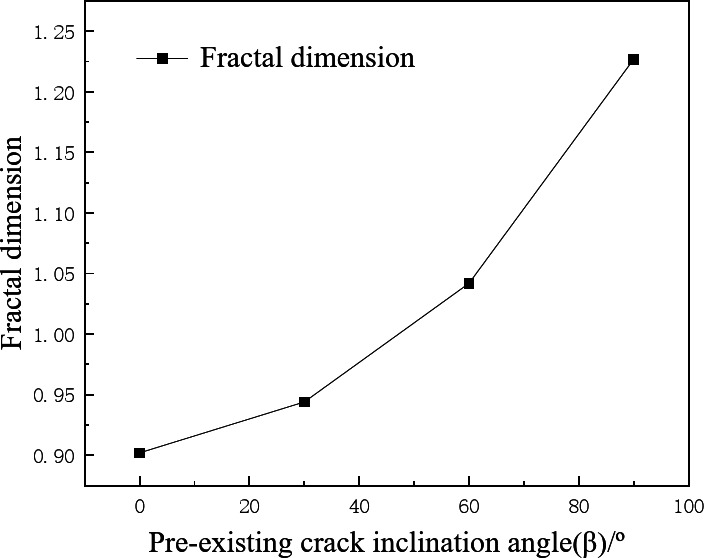
Relationship between pre-existing crack inclination angle and fractal dimension.
Figure 17 shows that the pre-existing crack angle has a significant impact on the propagation path of specimen, that is, as the angle increases, the fractal dimension D also shows an increasing trend. This is due to the fact as the angle of the pre-existing crack increases, the crack propagation path becomes longer and more complex. In the process of image binarization, the number of cracks intersecting with the coordinate grid increases, resulting in an elevated fractal dimension. Meanwhile, based on the analysis results in Sect. 3.3.1, it can be concluded that there is a positive correlation between the fractal dimension of newly expanded cracks in the specimen and its impact on compression peak stress.
Discussions
Influence of crack inclination angle on dynamic compressive strength under dynamic and static coupling
According to the uniaxial and triaxial dynamic compression stress-strain curves of rock-like specimens with cracks, the dynamic compressive strength of specimens can be obtained as a function of crack inclination angle, as shown in Fig. 18. Obviously, the influence of crack inclination angle on dynamic compressive strength varies under different confining pressure states. Without confining pressure, the dynamic compressive strength of specimen decreases first and then increases with the increase of the crack inclination angle. However, under confining pressure, the dynamic compressive strength of specimens with cracks increases with the crack inclination angle.
Fig. 18.
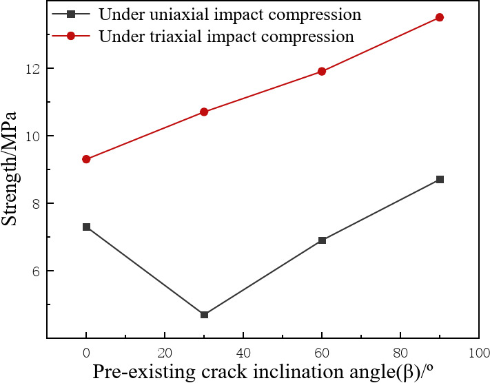
The dynamic compressive strength of specimens varies with crack inclination angle.
As can be seen from Fig. 18, under the condition of no confining pressure, the dynamic compressive strength of specimen varies in a “V” shape with the angle of the pre-existing crack inclination angle. Under uniaxial dynamic compression, the average compressive strength of intact specimens is 11.6 MPa, and the average compressive strength of specimens with pre-existing crack inclination angles of 0°, 30°, 60° and 90° are 7.51, 5.28, 6.71 and 9.27 MPa, respectively, which decreased by 35.25%, 54.48%, 42.15%, 20.1% compared with that of intact specimens. When the crack inclination Angle is 30°, the average value of the dynamic compressive strength of the specimen is the lowest, which indicates that it is the most prone to fracture under dynamic uniaxial compression. When the crack inclination Angle is 90°, the compressive strength of specimen is closest to that of intact specimen. This is because the direction of crack with inclination angle of 90° is parallel to the direction of impact load, making the influence of crack on the dynamic compressive strength of specimen smaller.
Under confining pressure stress, the dynamic compressive strength of specimens with pre-existing crack inclination angles of 0°, 30°, 60° and 90° are 20.4, 23, 25.2 and 29.5 MPa respectively, which are generally higher than those of specimens without confining pressure. This is due to the closure of primary cracks and pores within specimen under pressure, resulting in a significant increase in particle friction within specimen. At the same time, due to the effect of confining pressure, the normal stress on the fracture surface increases accordingly, resulting in the frictional bearing capacity of the crack exceeding the material’s cohesion and suppressing the slip of the crack. That is, the effect of confining pressure has a significant restraining effect on the propagation of microcracks inside the specimen. This is apparent not only in the increase in dynamic compressive strength, but also in the failure mode of rock specimens43,44.
Fracture mechanism of fractured rock under coupling effect of dynamic and static
Analysis of fracture mechanism of crack specimen under dynamic uniaxial compression
According to Griffith’s fracture mechanics theory45–48, when specimens with different crack inclination angles fracture under uniaxial compression, there is a critical crack Angle  , the value of which is around 45°.
When the long axis of crack is parallel to the loading axis (inclination β = 90°), tensile stress concentration occurs at the end of crack. The critical load of a tensile fracture is less than that of a compressional shear fracture. Therefore, the specimen will first develop a tensile crack at the end of the pre-existing crack, which is coplanar with the original crack surface and connected, resulting in splitting failure of the specimen49.
When the angle β between the long axis of the fracture and the loading axis is relatively small ( <β<90°), both tensile and shear-shear stresses are concentrated at the end of the crack, and the critical load of tensile fracture is close to the critical load of compressive shear fracture. As a result, tensile fracture and shear fracture occur almost simultaneously at the end of crack, and the secondary crack is coplanar with the original crack, resulting in tension-shear or shear-shear penetration, and eventually shear slip failure of the specimen49,50−53.
When the angle β between the long axis of the crack and the loading axis is relatively large (0 < β< ), the end of the crack will first undergo compression shear fracture due to the concentration of high compressive stress, but the range of compressive fracture zone is small. Subsequently, a large number of tensile fractures will occur in the large area of tensile stress concentration in the middle or end of crack. These tensile cracks gradually spread along the loading axis, forming airfoil cracks and forming multiple blocks with the original cracks and crushing zone, resulting in crushing, block rotation and stepped failure of the specimen49,50−53.
Based on the experimental analysis results in Sect. 3.2.1, it can be concluded that under dynamic uniaxial compression, specimen with a crack inclination angle of 30° is more prone to fracture compared to other fractured specimens. Due to no crack inclination of 45° was set for specimens in this study, it can be seen that specimens with a crack inclination of 30° belong to the critical crack inclination, which results in the lowest dynamic compressive strength. This is consistent with the experimental results of Q. Ping et al.45,48.
Analysis of fracture mechanism of crack specimen under dynamic and static coupling compression
As shown in Fig. 19, under the confining pressure, the force of specimen changes greatly, which makes it difficult for specimen to produce tensile failure along the radial direction under the action of axial dynamic load, and it cannot preferentially produce shear failure along the axial direction. In this case, the reason for the failure of specimen is the reflection tension generated by stress waves at the pre-existing crack of the specimen, resulting in axial tensile failure. At the same time, with the increase of confining pressure, the shear failure of the specimen will also occur along with the axial tensile failure.
Fig. 19.
The force failure model for specimens under triaxial impact compression. Note: S is tensile stress; C is the confining stress applied to specimen.
In the direction perpendicular to the stress wave, with the increase of the pre-existing crack inclination angle, the effective area of the specimen’s radial section (excluding the crack) gradually increases. Therefore, the specimens are becoming increasingly difficult to fracture, and the dynamic compressive strength of the specimen is positively correlated with the angle of the pre-existing crack inclination angle. Due to the direction of the 90° crack being perpendicular to the radial constraint force, the crack tends to close under confining pressure. Meanwhile, in the previous exploration, it was also shown that the 90° crack specimen is closest to a “homogeneous body”, therefore the 90° specimen has the highest dynamic compressive strength.
In summary, the presence of confining pressure makes the rock-like specimens subject to the reaction force during lateral deformation under dynamic loading, thereby confining the development of shear cracks. Especially under high confining pressure, the specimens cannot be developed in the radial direction, resulting in the reflection and stretching of stress waves leading to the failure of the specimen. Therefore, most rock-like specimens exhibit axial tensile failure. In addition, as the pre-existing crack inclination angle increases, the tensile section gradually increases, resulting in an increase in strength.
Advantages and limitations of the study
After reviewing the relevant literature54,55 and combining it with the research content mentioned earlier, we conducted a comparison between this study and the latest research technology, as depicted in Table 5 below:
Table 5.
Comparison of this study with the latest technology.
| Comparison Dimension | Content of This Study | Latest Technological Developments | Advantages of the Study |
|---|---|---|---|
| Research purpose | To explore the dynamic mechanical properties and fracture patterns of rock-like specimens under pre-existing cracks and different stress states. | Advances in the study of deep mining rock mechanics, including failure tests under dynamic-static combined loading. | Both this study and the latest technological developments focus on the behavior of deep rocks under complex stress states. |
| Testing methods | Using an SHPB device with active confining pressure for impact compression testing. | Dynamic-static combined loading tests, simulating the dynamic disturbance of deep rock mass under high static load. | The SHPB testing method used in this study complements the dynamic-static combined loading tests in the latest technology. |
| Failure mode analysis | Analyzed the failure modes of rock-like specimens under conditions with and without confining pressure, including tension and shear failure. | Studied the failure characteristics of red sandstone under dynamic-static combined loading, including shear failure and the degree of rock fragmentation. | Both this study and the latest technology focus on failure modes, but this study emphasizes more on the effects of crack angles and confining pressure. |
| Theoretical and practical significance | Provides a theoretical basis for preventing disasters related to rock instability. | Provides theoretical and experimental basis for the stability analysis of deep mining and mine pillars. | Both this study and the latest technology have important theoretical and practical significance. |
Although this study provides valuable insights, it does have some limitations. Firstly, laboratory-scale tests may not fully replicate the complexities of field conditions. For instance, when excavating deep rock tunnels, the original stress state of deep rocks is determined by the environment in which the rocks are situated and the distribution of surrounding rocks. Sometimes it is under a state of plane equal stress, but at other times, the original stresses in the plane are not equal. However, the SHPB system with active confining pressure can only simulate the stress state of deep rocks under plane equal stress conditions. Secondly, our study is limited to specific types of rock-like specimens and predefined crack geometries, which may restrict the generalizability of our results. Additionally, the dynamic loading rates used in our experiments are within a specific range, and the effects under different loading rates or cyclic loading conditions are not yet clear.
Conclusions
In this study, rock-like specimens were prepared based on similarity theory, and dynamic compression tests were conducted using the Split Hopkinson Pressure Bar (SHPB) device with an active confining pressure device. We investigated the effects of confining pressure and different crack angles on the dynamic fracture characteristics and mechanisms of rock-like specimens. Here are our main conclusions:
(1)Relationship between crack angle and dynamic compressive strength: Under different confining stresses, the crack angle significantly affects the dynamic compressive strength of specimens. In the absence of confining compressive stress, the dynamic compressive strength of cracked specimens first decreases and then increases with increasing crack inclination angle, with the intact specimen exhibiting the highest strength and the specimen with a 30° crack inclination angle showing the lowest strength. Under confining pressure, the dynamic compressive strength of specimens is generally higher than without confining pressure. The dynamic compressive strength of specimens with cracks increases with the crack inclination angle, and with the increase of strain rate, the strength of specimens with the same crack inclination angle gradually increases, showing a significant confining pressure effect and strain rate effect.
(2)Effect of confining pressure on deformation and failure: Confining pressure constraints significantly alter the deformation and failure process of specimens under impact loading. The deformation and failure process of rock-like specimens under uniaxial impact compression can be divided into four stages: elastic deformation, plastic deformation (crack stabilization-unstable expansion), yield, and failure unloading. Under confining pressure, the dynamic stress-strain curve of rock-like specimens can be divided into four stages: compaction, elastic deformation, crack propagation, and failure unloading.
(3)Effect of crack inclination angle on failure mode: Under uniaxial impact compression, the crack inclination angle significantly affects the failure mode of specimens, which can be classified into three distinct categories: tensile, shear, and tensile-shear. Under triaxial impact compression, the pre-existing crack angle significantly affects the propagation path of a specimen, with an increasing angle correlating with an increasing fractal dimension D. There is a positive correlation between the fractal dimension of newly expanded cracks in the specimen and its impact compression peak stress.
(4)Failure characteristics under confining pressure: Under confining pressure, it is difficult for specimens to produce tensile failure along the radial direction under the action of axial dynamic load, and they cannot preferentially produce shear failure along the axial direction. When the pre-existing crack inclination angle of rock-like specimens is 0° and 90°, the specimens exhibit axial tensile failure. When the pre-existing crack inclination angle is 30° and 60°, the cracks include both axial tensile and shear cracks, leading to the formation of tensile-shear compound failure.
Based on the above conclusions, we believe that the fracture mechanism of cracked specimens under dynamic and static coupling compression is much different from that under uniaxial compression with different crack angles. The presence of confining pressure subjects the rock-like specimen to reaction force when it deforms laterally under impact load, limiting the development of shear cracks. Especially at high confining pressures, specimens cannot develop in the radial direction, which makes the stress wave play a leading role in the reflection tensile failure of the specimens, resulting in most rock-like specimens showing axial tensile failure. Additionally, as the pre-existing crack inclination angle changes, the tensile section gradually increases, leading to an increase in strength.
The theoretical contribution of this study lies in the in-depth revelation of the mechanisms by which confining pressure and crack angles affect the dynamic fracture characteristics of rock-like specimens, providing new theoretical insights into the field of rock mechanics and engineering. Practically, our findings can help optimize blasting parameter design, enhancing the safety and efficiency of deep engineering projects.
From a practical standpoint, the findings of this study can guide engineers to consider the effects of confining pressure and crack angles when designing blasting parameters, leading to safer and more effective blasting operations. This has significant practical implications for deep engineering projects such as mining and tunnel excavation.
Despite providing valuable insights, this study has some limitations. Firstly, laboratory-scale tests may not fully simulate the complexities of field conditions. Secondly, our study is limited to specific rock-like specimens and predefined crack geometries, which may limit the universality of our results. Additionally, the dynamic loading rates used in our experiments are within a specific range, and the effects under different loading rates or cyclic loading conditions are unclear. Suggestions for future research:
(1)Expand sample range: Future research should consider a wider variety of rock types and natural crack configurations to enhance the universality of the findings and provide a more comprehensive understanding of rock behavior under dynamic loads.
(2)Multi-axial and cyclic loading studies: Investigating the response of fractured rocks to multi-axial dynamic loading and cyclic stress conditions could offer deeper insights into the fatigue behavior and long-term stability of rock masses, which is crucial for applications such as underground construction and geological carbon sequestration.
(3)Environmental factors consideration: Future studies should also consider the effects of environmental factors such as pore pressure, temperature, and chemical interactions within the rock mass, which could significantly influence rock behavior and stability.
Acknowledgements
The authors would like to acknowledge the anonymous reviewers for their valuable and constructive comments. This research is supported by the Graduate Innovation Fund of Anhui University of Science and Technology (No. 2024cx2018), Research grants project for bringing in talents of Anhui University of science and technology, National Natural Science Foundation of China (No. 52104116, No. 52074009).
Author contributions
Author contributions Jinjin Ge: Overall design and guidance. Yongqi Jia: Experimental data processing and manuscript writing. Wei Huang: theoretical analysis. Meilu Yu: Reviewed the manuscript. Suqian Ni: Test instrument operation and assistance. Ying Xu: Reviewed the manuscript. Leilei Yu: Help with manuscript writing. Keke Gu: Specimen making and maintenance.
Data availability
The datasets generated and analyzed during the current study are available from the corresponding author upon reasonable request.
Declarations
Competing interests
The authors declare no competing interests.
Footnotes
Publisher’s note
Springer Nature remains neutral with regard to jurisdictional claims in published maps and institutional affiliations.
References
- 1.Xie, H., Gao, F. & Ju, Y. Research and Exploration of Deep Rock Mechanics. J. Rock. Mech. Eng.34(11), 2161–2178. 10.13722/j.cnki.jrme.2015.1369 (2015). [Google Scholar]
- 2.Ge, J. et al. Deep rock blasting in the main direction of crack propagation and the relationship between in-situ stress., Journal of vibration and shock, vol. 42, no. 04, pp. 54–64, (2023). 10.13465/j.cnki.jvs.2023.04.007
- 3.Xu, Y. et al. Experimental study on effect of charge uncoupling coefficient on crack growth in rock blasting under initial ground stress. Blasting39(04), 1–9 (2022). [Google Scholar]
- 4.Ge, J. Model test study on rock blasting crack growth under initial stress. Anhui Univ. Sci. Technol.10.26918/d.cnki.ghngc.2020.000423 (2020). [Google Scholar]
- 5.Wang, J., Zou, B. & Hu, L. Advance and Trend in Smooth Blasting Technology for Tunnel and Underground Engineering. Chin. J. Undergr. Space Eng.9(04), 800–807 (2013). [Google Scholar]
- 6.Wu, X. et al. Experimental study on dynamic mechanical failure characteristics of crack concrete specimens with different inclination Angles. J. Vib. Shock. 43(04), 142–149 (2024). [Google Scholar]
- 7.Liu, H. et al. Experimental study of SHPB similar materials for dynamic failure of jointed rock mass. Rock. Soil. Mech.35(03), 659–665 (2014). [Google Scholar]
- 8.Yang, R. et al. Packing material to the influence of joints and rock dynamic performance simulation test. J. Vib. Shock. 35(12), 125–131 (2016). [Google Scholar]
- 9.Yan, Z. et al. Dynamic cracking behaviors and energy evolution of multi-flawed rocks under static pre-compression. Rock. Mech. Rock. Eng. vol. 54, 5117–5139 (2021). [Google Scholar]
- 10.Zhang, L. et al. Crack development and damage patterns under combined dynamic-static loading of parallel double fractured rocks based on DIC technique. Acta Geotech.18(2), 877–901 (2023). [Google Scholar]
- 11.Liu, E. et al. Study on the Effect of Precrack on Specimen Failure Characteristics under Static and Dynamic Loads by Brazilian Split Test. Math. Probl. Eng.2021(1), 5747768 (2021). [Google Scholar]
- 12.LIU Tingting, LI Jianchun, LI Haibo, et al. Energy analysis of stress wave propagation across parallel nonlinear joints[J]. Chinese J. Rock Mech. Eng.32(8), 1610–1617 (2013).
- 13.ZOU Fei, LI Haibo, ZHOU Qingchun, et al. Experimental study of influence of joint space and joint angle on rock fragmentation by TBM disc cutter [J]. Rock and Soil Mechanics, 33(6), 1640–1646 (2012).
- 14.LIU Hongyan, HUANG Yushi, LI Kaibing,et al. Test study of strength and failure mode of pre-existing jointed rock mass [J]. Rock and Soil Mechanics, 34(5), 1235–1241 (2013).
- 15.Hongyan, L. I. U. et al. Similar material test study of dynamic failure of jointed rock mass with SHPB [J]. Rock Soil. Mech.35(3), 659–665 (2014). [Google Scholar]
- 16.Jianguo, W. A. N. G. et al. Impact response tests of layered medium with SHPB [J]. J. Vib. Shock. 34(19), 192–197 (2015). [Google Scholar]
- 17.Yang, Y. A. N. G., Renshu, Y. A. N. G. & Jianguo, W. A. N. G. Simulation material experiment on dynamic mechanical properties of jointed rock affected by joint thickness [J]. J. China Univ. Min. & Technol.45(2), 211–216 (2016). [Google Scholar]
- 18.Renshu, Y. A. N. G. et al. Simulation material experiment on the dynamic mechanical properties of jointed rock affected by joint-filling material [J]. J. Vib. Shock. 35(12), 125–131 (2016). [Google Scholar]
- 19.Gang, M. A. et al. Dynamic characteristics and fracture energy dissipation of fiber reinforced concrete beams under low-velocity impact [J]. J. Vib. Shock. 41(8), 208–216 (2022). [Google Scholar]
- 20.Samal, R. K. & Mishra, S. Dynamic Characterization of Synthetic Sandstone Rock under the Influence of Self-Induced Crack., Eurock 2024 - New Challenges in Rock Mechanics and Rock Engineering - an ISRM Regional Symposium, Alicante, Spain, July 15–19, 2024 (2024).
- 21.Mishra, S., Chakraborty, T. & Basu, D. High Strain Rate Response of Soils - A Review. Japanese Geotech. Special Publication. 3(2), 80–85 (2016). [Google Scholar]
- 22.Mishra, S., Chakraborty, T., Basu, D. & Lam, N. Characterization of Sandstone for Application in Blast Analysis of Tunnel. Geotechnical Testing Journal, ASTM, 43. DOI: (2019). 10.1520/GTJ20180270
- 23.Lou, C. et al. Dynamic mechanical characteristics of deep Jinping marble in complex stress environments. J. Rock Mech. Geotech. Eng.16(2), 630–644 (2024). [Google Scholar]
- 24.Zhang, A. et al. Dynamic failure behavior of Jinping marble under various preloading conditions corresponding to different depths. Int. J. Rock Mech. Min. Sci.148, 104959. 10.1016/j.ijrmms.2021.104959 (2021). [Google Scholar]
- 25.Li, X. et al. Innovative testing technique of rock subjected to coupled static and dynamic loads. Int. J. Rock Mech. Min. Sci.45(5), 739–748 (2008). [Google Scholar]
- 26.Yin, Z. et al. Failure characteristics of high stress rock induced by impact disturbance under confining pressure unloading. Trans. Nonferrous Met. Soc. China. 22(2), 175–184 (2012). [Google Scholar]
- 27.Kang, P. et al. Static and dynamic mechanical properties of granite from various burial depths. Rock Mech. Rock Eng.52, 3545–3566 (2019). [Google Scholar]
- 28.You, W. et al. Effect of Confining Pressure and Strain Rate on Mechanical Behaviors and Failure Characteristics of Sandstone Containing a Pre-existing Flaw. Rock Mech. Rock Eng., pp. 1–19, (2021).
- 29.Kuang, L., Chen, G. & Wang, T. Mix Design of Similar Materials for Sandstones with Different Shear Modulus. Chin. J. Undergr. Space Eng.88(06), 1173–1177 (2012). [Google Scholar]
- 30.Ge, J. & Xu, Y. Impact compression properties of artificial cemented sand material under active confining pressure. J. VibroEng.22(2), 868–879 (2020). [Google Scholar]
- 31.Tian, W. et al. A preliminary research on dynamic mechanical properties and energy dissipation rule of 3D printed fractured rock. Chin. J. Rock Mechan. Eng.41(03), 446–456 (2022). [Google Scholar]
- 32.Vrkljan, I. Rock engineering in difficult ground conditions-soft rocks and karst. CRC Press., (2009).
- 33.Ge, J. Study on Dynamic Mechanical Properties of Cemented Sand Like Material under Confining Pressure. Anhui Univ. Sci. Technol., (2017).
- 34.Wang, L. Foundation of stress wave, Beijing: National Defense Industry Press, pp. 52–59, (2005).
- 35.Liu, W. & Shen, J. Mechanical experimental study on fracture mode of real rock specimen with single crack. Chin. J. Rock Mechan. Eng.35(06), 1182–1189 (2022). [Google Scholar]
- 36.Li, H. Rock fracture mechanics, Chongqing: Chongqing University Press, pp. 66–84, (1988).
- 37.Sih, G. Strain-energy-density factor applied to mixed mode crack problems. Int. J. Fract.10(3), 305–321 (1974). [Google Scholar]
- 38.Xing, G. et al. Energy evolution and fracture mechanism of prefabricated fracture 3D printed rock mass. J. Undergr. Space Eng.19(04), 1177–1187 (2023). [Google Scholar]
- 39.Jin, A. et al. 3D printing based on the technology of DIC joint specimens rupture mechanism study. Rock. soil. Mech.41(10), 3214–3224 (2020). [Google Scholar]
- 40.Guo, Q. et al. Prefabricated crack strength characteristics and failure modes of granite test. J. Eng. Sci.9(1), 43–52 (2019). [Google Scholar]
- 41.Luo, M. et al. 3D digital rock modeling of the fractal properties of pore structures. Mar. Pet. Geol.122, 104706 (2020). [Google Scholar]
- 42.Li, B., Yang, K. & Liu, Y. Fractal theory and Fractal Parameter calculation method. Tool. Technol.38(12), 80–84 (2004). [Google Scholar]
- 43.Huang, Y. et al. Experimental study on triaxial compression mechanical properties of fractured rocklike materials. Chin. J. Geotech. Eng.38(07), 1212–1220 (2016). [Google Scholar]
- 44.Yang, S. & Liu, X. Experimental study on dilatation characteristics of intermittent precast fractured marble under different confining pressures. Chin. J. Geotech. Eng.34(12), 2188–2197 (2012). [Google Scholar]
- 45.Ping, Q. et al. Saturated fractured sandstone research on dynamic mechanical properties and crack extension rule. J. Rock. Mech. Eng.43(S1), 3131–3139 (2024). [Google Scholar]
- 46.Ping, Q. et al. Study on mechanical properties and energy consumption of fissured sandstone with different dip angles under impact load. Shock Vib.1, 5335357 (2022). [Google Scholar]
- 47.Li, D. et al. With prefabricated crack dynamic mechanical damage marble SHPB experimental study. J. rock. Mech. Eng.4(12), 2872–2883 (2017). [Google Scholar]
- 48.Wang, W. et al. Mechanical properties of rock-like samples with fractures of different inclination angles under SHPB loading. Sci. Technol. Rev.34(18), 246–250 (2016). [Google Scholar]
- 49.Chen, X., Liao, Z. & Li, D. Uniaxial compression experimental study on the influence of joint dip Angle and connectivity rate on rock mass strength and deformation. Chin. J. Rock Mechan. Eng.30(44), 781–789 (2011). [Google Scholar]
- 50.Shen, B., Stephansson, O., Einstein, H. H. & Ghahreman, B. Coalescence of fractures under shear stresses in experiments. J. Phys. Res.100(B4), 239–249 (1995). [Google Scholar]
- 51.Bobet, A. & Einstein, H. H. Fracture coalescence in rock-type material under uniaxial and biaxial compression. Int. J. Rock. Mech. Min. Sci.35(7), 836–888 (1998). [Google Scholar]
- 52.Wong, L. N. Y. & Einstein, H. H. Systematic evaluation of cracking behavior in specimens containing single flaws under uniaxial compression. Int. J. Rock. Mech. Min. Sci.46(2), 239–249 (2009). [Google Scholar]
- 53.Wong, L. N. Y. & Einstein, H. H. Crack coalescence in molded gypsum and Carrara marble: part1-macroscopic observations and interpretation. Rock Mech. Rock Eng.43(3), 475–511 (2009). [Google Scholar]
- 54.Li, Xibing & Gong Fengqiang. Research progress and prospects of rock mechanics in deep mining based on combined dynamic and static loading mechanical tests. J. Coal. Sci. Eng.46(3), 846–866. https://doi.org/10.132/25/j.cnki.jccs.YT21.0 (2021). [Google Scholar]
- 55.Yang Hui, W. et al. Dynamic Mechanical Properties and Penetration Resistance of Granite with Different Weathering Degrees[J]. Explosives Impacts. 44(10), 49–66 (2024). [Google Scholar]
Associated Data
This section collects any data citations, data availability statements, or supplementary materials included in this article.
Data Availability Statement
The datasets generated and analyzed during the current study are available from the corresponding author upon reasonable request.


