Abstract
Friction stir processing (FSP) is successfully employed to alleviate their hook defects of friction stir lap welding (FSLW) of aluminum alloys. The mechanical properties and microstructural characteristics are compared and analyzed between the FSLW&FSP joint fabricated by FSLW and FSP and the FSLW joint. The microstructural analysis shows that the hook defect zone at the advancing side of the FSLW joint is changed into the overlap zone (OZ) of the FSLW&FSP joint due to microstructure reconstruction caused by performing the FSP. The heterogeneous and coarse grains at the hook defect zone of the FSLW joint are transformed into refined and equiaxed grains at the OZ of the FSLW&FSP joint as a result of dynamic recrystallization. The results of tensile tests show that tensile strength and fracture toughness of the FSLW&FSP joint are 85.7% and 220% higher compared to those of the FSLW joint, respectively. The cross sections of broken lap joints reveal that their failure location is shifted from the hook defect at AS of the FSLW joint to the thermo-mechanically affected zone of the FSP zone of FSLW&FSP joint. The combined action of effective sheet thickness increasement, microstructure uniformity, grain refinement, and local stress concentration reduction act as the strengthening mechanism of the lap joint of aluminum alloys.
Keywords: Friction stir lap welding, Hook defect, Microstructure reconstruction, Strengthening mechanism
Subject terms: Structural materials, Mechanical properties, Metals and alloys, Engineering, Materials science
Introduction
The new energy vehicles (NEVs) are gradually replacing traditional engine-driven vehicles to reduce emissions and save energy1. The application of lightweight material is the main direction of development for improving the endurance of NEVs by reducing the weight. Among lightweight materials, aluminum (Al) alloys are considered to be one of the most appealing options in the NEV industry due to their high specific strength, strong corrosion resistance, and low cost2–4. In the manufacturing of NEVs, an Al alloy welding structure is an essential part of manufacturing multifunctional and complex-shaped components. During the traditional fusion welding process, the oxide film on the surface of Al alloys can hinder the bonding of metals and cause the formation of pores and slag inclusion in the weld joint, which is one major disadvantage of joining Al alloys5–7.
Friction stir welding (FSW) possesses several advantages of joining Al alloys due to the suppression of grain coarsening in joints and the shatter of oxide film on the faying surface due to low heat input and strong mechanical stirring8. It suggests that FSW can overcome the solidification defects formed by traditional fusion welding technology9. However, the FSW of Al alloys in a lap configuration is still facing an enormous challenge due to the formation of hook defects, which can significantly decrease the strength of the joint10–12. In the friction stir lap welding (FSLW) of Al alloys, the hook defect is formed by the upward migration of the overlapping interface caused by the downward pressure from the rotation tool13,14. Therefore, the nature of FSLW determines the inevitable presence of hook defects in the Al alloy joint. Hook defects can reduce the effective sheet thickness (EST) of FSW lap joints, thereby reducing their mechanical properties. Besides, the hook defects preferentially act as sources of fatigue crack initiation due to the high stress concentration, which causes the deterioration of the fatigue strength of the Al alloy FSLW joint15,16.
Reducing the impact of hook defects on the mechanical properties of Al alloy FSLW joints is of great practical value and research value. As reported, the research on hook defects mainly focuses on regulating material flow behavior by optimizing welding process parameters and tool morphology, thereby weakening their negative impact on FSLW joint strength17,18. Yue et al.19 investigated the FSLW of Alclad and 2024 Al alloy using tools with full-threaded and reverse-threaded pins. They found that the FSLW joint fabricated by the reverse-threaded pin obtained better lap shear failure strength due to forming a more significant EST and lap width. Costa et al.20 fabricated the FSLW joint of AA5754-H22 thin sheets at welding speeds of 350 and 1000 mm/min. They reported that the dimensions of the hook defect increased with the increase in welding speed. However, their results contradict Yazdanian et al. results for AA 6060-T6 FSLW21. It can be explained as the differences in the thickness of the workpiece and the tool rotational speed in the welding process. Shirazi et al. analyzed the effects of tool rotation speed on the hook defect formation of FSLW of AA5456 and reported that the height of the hook defect increased with the increase in tool rotation speed22.
In the present study, the adverse effects of hook defects of Al alloys FSLW joint can only be alleviated but not eliminated. Friction stir processing (FSP) can be used to achieve microstructure modification of polycrystalline metallic materials by refining the microstructure or introducing particle or powder materials into the base material23. Abdollahzadeh et al. used FSP to evenly distribute silicon carbide nanopowders into the magnesium alloy before the FSW of AZ31 magnesium alloy to 6061 Al alloy, ultimately achieving an improvement in joint strength24. Gao et al. successfully utilized FSP to microstructural homogenization of the AA4343-clad AA3003 sheet, thereby improving the interfacial strength25. The author proposed eliminating hook defects by reconstructing the microstructure of FSLW joints through FSP based on its ability to achieve microstructure modification of polycrystalline metallic material. Firstly, the Al alloy lap joints with hook defect were fabricated using FSLW. Subsequently, FSP was carried out near the hook defect of the FSLW joint. In addition, the strengthening mechanisms of Al FSLW joints were discussed by microstructure analysis, tensile shear tests, and fracture surface observation. The method may provide references for FSLW of other light metals, which is essential for fabricating higher-strength joints.
Experimental procedure
In this study, the 6061-Al alloy in T6 temper condition (AA6061-T6) of 2 mm thickness was employed as a base material (BM). The chemical composition and mechanical properties of the BM are indicated in Table 1. Workpieces with dimensions of 100 (width) × 150 (length) mm2 were machined from the as-received commercial AA6061-T6 sheets. The grease and dust on the surface of the workpieces were cleaned with acetone. Two workpieces were fixed on the welding experiment workbench in the lap-joint configuration with an overlapped area of 150 mm × 50 mm in Fig. 1.
Table 1.
Chemical compositions and mechanical properties of AA6061-T6 (alloy elements, wt%).
|
Chemical compositions |
Al | Cr | Cu | Fe | Mg | Mn | Si | Ti | Zn | ||
| Bal. | 0.17 | 0.23 | 0.4 | 0.9 | 0.11 | 0.6 | 0.12 | 0.04 | |||
|
Mechanical properties |
Ultimate tensile strength | Elongation | Yield strength | ||||||||
| 327 MPa | 17.4% | 271 MPa | |||||||||
Fig. 1.
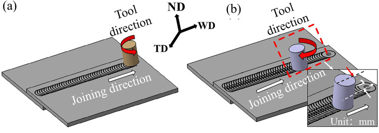
The schematic of (a) FSLW of AA6061-T6 sheets and (b) FSP of AA6061-T6 FSLW joint.
The two-step AA6061-T6 lap joining experiments were designed. The AA6061-T6 FSLW (Fig. 1(a)) was the first step in fabricating lap joints. The FSP (Fig. 1(b)) was used as the second step to eliminate the hook defect of the FSLW joint. The joint obtained by the two-step lap joining experiments was named the FSLW&FSP joint. The FSLW and FSP experiments were executed by tool-FSLW and tool-FSP (Table 2) using a custom-made friction stir welding machine (DH-FSW-1517-08, Jingke Daheng, China). Except for the penetration depth and tool rotation direction, other parameters were set to be consistent in FSLW and FSP experiments, as presented in Table 3. The FSLW experiments (Fig. 1(a)) were performed under the condition of anticlockwise rotation of the tool-FSLW, which indicated that the loading side corresponded to the advancing side (AS) of the FSLW joint. After the FSLW of AA6061-T6, the tool-FSP was offset by 7 mm toward the AS of the joint, ensuring that it is approximately located near the hook defect (Fig. 1(b)). Then, the tool-FSP with clockwise rotation was applied to complete the FSP of the AA6061-T6 FSLW joint, as schematically presented in Fig. 1(b). Besides, the axial force and torque histories were recorded by the data acquisition system of the FSW machine, which was used to evaluate the influence of heat input generated in the FSLW and FSP on the FSLW and FSLW&FSP joints4.
Table 2.
Dimension and geometry of the tool used in FSLW and FSP.
| Tool-FSLW | Tool-FSP | |
|---|---|---|
| Shoulder Diameter | 20 mm | 10 mm |
| Shoulder type | Concave | Concave |
| Probe length | 3 mm | 1.4 mm |
| Pin diameter | 6 mm | 3 mm |
| Pin pitch | 1 mm | 0.5 mm |
| Pin thread | Trapezoidal thread | Trapezoidal thread |
| Pin direction | Right-hand | Right-hand |
Table 3.
Process parameters for the FSLW and FSP experiments.
| Parameters | Rotational speeds |
Traverse speed | Tilt angle | Penetration depth |
Tool rotational diction |
|---|---|---|---|---|---|
| FSLW | 1200 rpm | 75 mm/min | 1.5° | 3.2 mm | Anticlockwise |
| FSP | 1.7 mm | Clockwise |
After welding, to verify the effectiveness of FSP in eliminating hook defects, two metallographic specimens were sectioned from the FSLW joint (Fig. 1(a)) and FSLW&FSP joint (Fig. 1(b)) using an abrasive waterjet cutting machine, respectively. The metallographic specimens were standard ground by sandpapers (360#, 600#, 800#, 1000#, and 1200#) and polished using colloidal silica suspension (1 μm and 0.04 μm). The hook defect morphology changes between the FSLW joint and the FSLW&FSP joint were analyzed by optical microscope (OM; A1m Axio Imager, Carl Zeiss, Germany). To further observation of microstructure characteristics by a field emission scanning electron microscopy (FE-SEM: Sigma 500, Carl Zeiss AG, Germany) and a Hikari Plus electron backscattered diffraction (EBSD: Oxford C-nano, UK), the metallographic specimens of FSLW and FSLW&FSP joints subsequently were electropolished with 90 ml CH3OH + 10 ml HNO3 solution at 25℃ at 16 V.
The microhardness tests of the FSLW joint and FSLW&FSP joint were carried out along the horizontal centerline of the top AA6061-T6 sheet using a Vickers microhardness tester (HXD-2000TMC/LCD 181101×, Shanghai Tai Ming Optical Instrument Co. Ltd., China). 4.8 N load and 10 s dwell time were employed for hardness test parameters. The tensile shear test specimens were machined perpendicular to the welding direction. The tensile shear samples of FSLW and FSLW&FSP joints have identical dimensions (width: 16 mm; length: 150 mm). To avoid generating eccentric loads on lap joints, two spacers were placed at the right and left ends of the tensile shear test specimens. At least 5 tensile shear tests were conducted on an MTS C44 electronic universal testing machine at a constant speed of 0.5 mm/min. The cross sections of tensile fracture FSLW and FSLW&FSP joints were prepared and observed to analyze their fracture locations. Besides, the characterization of fracture surfaces of the FSLW and FSLW&FSP joints was investigated by SEM.
Results and discussion
Process response and weld appearance
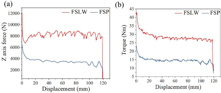
Process responses in FSLW and FSP processes including axial force and torque are shown in Fig. 2. The axial force and torque are caused by the mechanical interaction between the rotation tool and BM, which are related to the heat input during the joining26. The energy input ( ) generated in the FSLW and FSP processes can be approximately compared using the equation below27.
 |
1 |
Fig. 2.
Process responses of FSLW and FSP process: (a) Z-force and (b) torque.
Based on the Eq. 1, the energy input has a positive correlation with the  (torque;
  ) and
) and  (the tool rotation speed; rpm). As mentioned in Sect. 2 (Experimental procedure), the tool rotation speed (1200 rpm; Table 1) in FSLW and FSP are identical. The axial force (Fig. 2(a)) and torque (Fig. 2(b)) obtained from the FSP are significantly lower than those from the FSLW. Besides, the tool with bigger dimension in FSW can generate more heat energy than that with smaller dimension under same welding conditions. As list in Table 2, the dimension of tool used in FSLW is much larger compared to that in FSP28. Therefore, it can be concluded that the energy input in the FSP is significantly less than that in the FSLW.
Figure 3 shows the weld appearance of the FSLW and the FSLW&FSP joints. As shown in Fig. 3(a), the surface of the FSLW joint at AS is relatively smoother than that at the retreating side (RS). It could be explained by the presence of higher plastic material flow performance at AS5. The welding zone (WZ) width of the FSLW joint (approximately 20 mm; Fig. 3(a)) is smaller compared with that of the FSLW&FSP joint (approximately 22 mm; Fig. 3(b)). Since the tool used in FSP was shifted to the distance of 7 mm from the center position of FSLW joint (as mentioned in Sect. 2), the partial WZ of FSP (WZ(FSP)) at AS overlaps with the WZ of FSLW (WZ(FSLW)) at AS. In FSP, compared with the RS, the AS with a more significant shear force gradient can achieve microstructure reconstruction near hook defects with less energy input29. Note that both sides of the FSLW&FSP joint (Fig. 3(b)) are the RS of WZ(FSLW) and the RS of WZ(FSP), respectively. The load on the upper plate of FSLW&FSP joints was transmitted to the RS of WZ(FSP) during the tensile shear tests. The RS of the WZ in Al alloys FSW joint tends to demonstrate the formation of lower stress concentration and free-defects due to and caused by flow directions of the plastic material, which could lead to its superior mechanical performance compared to the AS of the WZ30–32.
Fig. 3.
The weld appearance of (a) the FSLW joint and (b) the FSLW&FSP joint.
Characteristics of macrostructure by OM
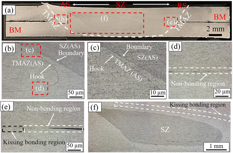
The cross sections of the FSLW joint (Fig. 4) and FSLW&FSP joint (Fig. 5) were analyzed and compared by observation of the OM images. The FSLW joint contains three typical regions: SZ, the thermo-mechanically affected zone (TMAZ), and BM, as shown in Fig. 4. There are different appearances of defects between the AS (Fig. 4(b)) and the RS (Fig. 4(e)) of the FSLW joint due to differences in plasticized material flow33. The defect at AS of the FSLW joint can be divided into two parts: distinct hook defect with weak joining strength on the upper side (Fig. 4(c)) and non-bonding region without joining strength on the lower side (Fig. 4(d)). The diminishing propagation effect of energy input from top to bottom of AA6061-T6 sheets assembly during the FSLW is the reason for changes in defects at AS of the joint34–37. The hook defects can reduce the EST related to the mechanical properties of FLSW joints of Al alloys38,39. The coincidence of the hook defect tip and TMAZ/SZ boundary in the FSLW joint (Fig. 4(c)) greatly reduces the fatigue performance of lap joints40,41. Therefore, it is very necessary to study the elimination of hook defects in FSLW joints. By contrast, the kissing bonding defect (Fig. 4(f)) observed at RS of the FSLW joint extends from the non-bonding region (Fig. 4(e)) to the upper part of the SZ. The kissing bonding defect is formed by the insufficient stirring of the oxide layer on the overlapping surface of the workpieces42,43. In this present study, the kissing bonding defect at RS has no negative impact on the mechanical properties of the FSLW joint due to the loading side corresponding to the bottom plate. Therefore, in this paper, eliminating the defect at RS of the FSLW joint was not considered.
Fig. 4.
(a) Macrograph of the AA6061-T6 FSLW cross section with white rectangles indicating typical regions; (b) a magnified view of the hook defect zone at AS in (a); a magnified view of (c) the upper and (d) the lower part of hook defect zone in (b); (e) a magnified view of the defect at RS in (a); (f) a magnified view including the kissing bonding defect and partial SZ in (a).
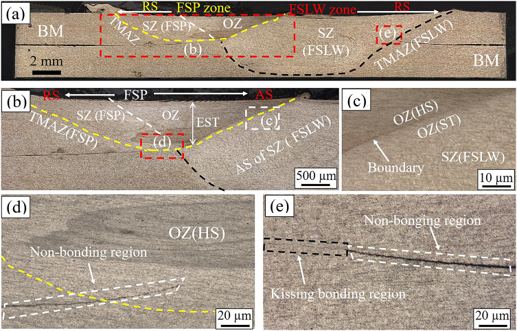
Fig. 5.
(a) Macrograph of the AA6061-T6 FSLW&FSP cross section with white rectangles indicating typical regions; a magnified view (b) in (a), (c) and (d) in (b); (e) a magnified view of the defect at RS in (a).
Compared with the FSLW joint, the cross section of the FSLW&FSP joint (Fig. 5(a)) has significant changes as a result of the stirring action of the tool-FSP. The FSLW&FSP joint can be divided into the overlap zone (OZ), SZ of FSLW (SZ(FSLW)), TMAZ of FSLW (TMAZ(FSLW)) at RS, SZ of FSP (SZ(FSP)), and TMAZ of FSP (TMAZ(FSP)) at RS. In the FSP, the material near the hook defect including SZ(FSLW) and TMAZ(FSLW) at AS of the FSLW joint underwent severe stirring action under the shear force and downward pressure of tool-FSP. Besides, the residual oxide film fragments forming hook defects (Fig. 4(b)) were thoroughly shattered and dispersed in the SZ(FSP). The energy input generated in the FSP may have an impact on the SZ(FSLW) at AS. Therefore, the OZ (Fig. 5(b)) was formed by the partial overlap of the WZ (FSLW) (i.e., SZ(FSLW) and TMAZ(FSLW)) at AS and the WZ (FSP) (i.e., SZ(FSP) and TMAZ(FSP)) at AS during the fabrication of FSLW&FSP joint. The OZ can be subdivided into OZ(HS) formed by overlapping hook defect (i.e., the SZ and TMAZ of AS of FSLW joint) and SZ(FSP), and OZ (ST) formed by overlapping the SZ(FSLW) and TMAZ(FSP), as shown in Fig. 5(c). The appearance of the FSLW&FSP joint (Fig. 5(d)) suggests that the hook defect at AS of the FSLW joint was successfully eliminated due to the microstructure reconstruction caused by the stirring action of the tool-FSP. Therefore, the EST of the AA6061-t6 lap joint in vertical directions after FSP was improved by eliminating the hook defect at AS of the FSLW joint. The non-bonding regions (Fig. 5(d and e)) could be treated as pre-cracks of the FSLW joint, which is the inevitable existence of the lap joint29. It is worth noting that the area above the tip of the non-bonding region at the AS of the FSLW&FSP joint is OZ(HS).
Characteristics of microstructure by EBSD
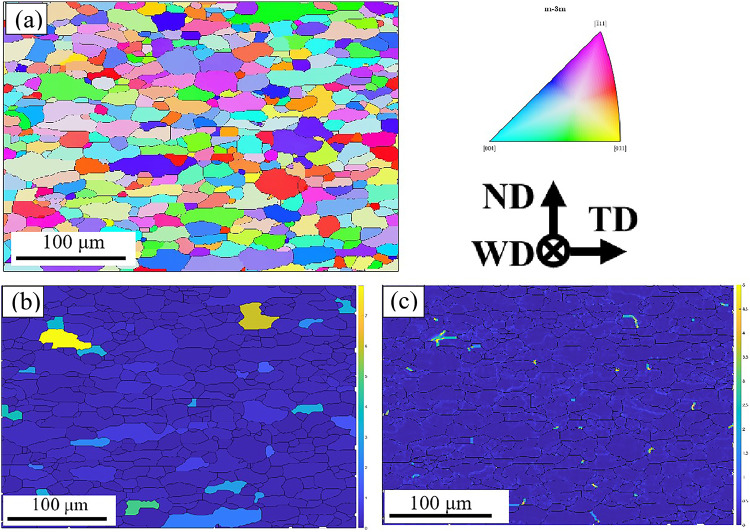
The IPF map of the BM shows a combination of elongated and coarse grain structures with an average size of 24.4 ± 2.8 μm (Fig. 6(a)). A critical of 15° was used for grain identification. The GOS map indicates that the misorientation angle of grains greater than the threshold value of 2°were recrystallized (Fig. 6(b)). Besides, the KAM valve of BM (0.13; Fig. 6(c)) presented intergranular misorientation related to the local strain concentration5.
Fig. 6.
(a) IPF, (b) GOS, and (c) KAM maps of BM.
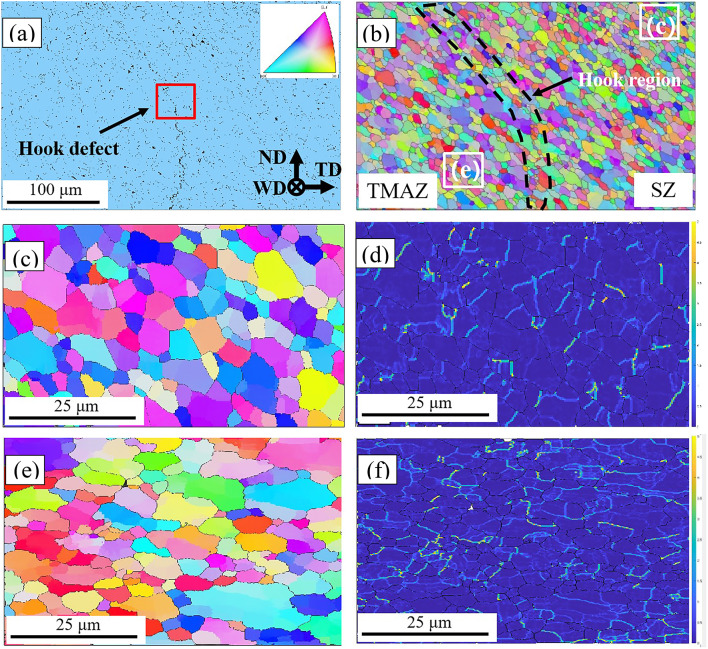
The SEM image obtained at the AS of the FSLW joint exhibits a clear morphology of hook defect, as shown in Fig. 7(a). EBSD IPF maps corresponding to the SEM image of the hook defect are exhibited in Fig. 7(b). The hook defect approximately divides the IPF map (Fig. 7(b)) into two central symmetry figures on the left and right sides. The grains near the hook defect exhibit a trend of elongation due to the combined action of the shear strain from the stirring pin and the downward pressure from the shoulder in the FSLW. The grain size in the vicinity of the hook defect is significantly smaller than that of BM due to dynamic recrystallization caused by thermal-mechanical coupling44,45. Besides, the grains on both sides of the hook defect exhibit different morphologies. According to previous research, the right side of the hook defect (Fig. 7(c)) with an average grain size of 9.4 ± 1.6 μm could be identified as SZ, since both possess similar structures with homogeneous shape and refined size19. By contrast, the left side of the hook defect (Fig. 7(e)) presents a relatively larger grain size (14.7 ± 2.1 μm) and more heterogeneous grain structure, as a result of which may experience incomplete dynamic recrystallization, and thus is regarded as TMAZ4,46. Besides, the higher KAM valve was observed from TMAZ (0.306; Fig. 7(f)) than that from SZ (0.255; Fig. 7(d)), which could be explained by the severe and nonuniform plastic deformation of TMAZ during FSLW5.
Fig. 7.
(a) SEM image of hook defect zone at AS of FSLW joint; (b) IPF map corresponding to SEM image; IPF maps and KAM maps for (c-d) SZ and (e-f) TMAZ in (b).
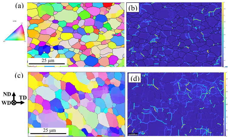
Figure 8 exhibits the microstructure characteristics of the partial FSP zone, i.e., SZ(FSP) and TMAZ(FSP) in Fig. 5(b). The grains with slightly bigger sizes were found in the IPF maps of SZ(FSP) (10.4 ± 1.7 μm) and TMAZ(FSP) (15.3 ± 2.2 μm) of the FSLW&FSP joint in Fig. 8(a & c) compared with the SZ and TMAZ of the FSLW joint. More heat input during FSW is beneficial for grain modification and grain size reduction47. Therefore, slightly bigger sizes in the TMAZ(FSP) and SZ(FSP) are attributed to relatively less heat input in FSP (Fig. 2). The KAM values of SZ(FSP) and TMAZ(FSP) were respectively confirmed as 0.224 (Fig. 8(b)) and 0.288 (Fig. 8(d)), which were lower than those of SZ and TMAZ in the FSLW joint. The relatively smaller stirring action of tool-FSP is responsible for these results by analysis of process responses of FSP and FSLW (Fig. 2).
Fig. 8.
IPF maps and KAM maps of FSLW&FSP joint: (a-b) SZ(FSP) and (c-d) TMAZ (FSP).
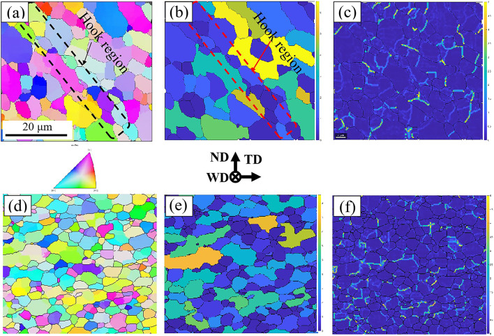
The EBSD IPF map (Fig. 9(a)) marked using a red rectangle in Fig. 7(a) is amplified for detailed observation of grain structure near the hook defect. Several grains with extremely small sizes exist in the location of hook defects, as shown in Fig. 9(a). The corresponding EBSD GOS map (Fig. 9(b)) with blue color indicates the misorientation angle of grains is smaller than 2°, which could be explained that these grains did not undergo dynamic recrystallization. Compared with the BM, a sharp increase in the local strain concentration was observed in the KAM map of the hook defect (0.442; Fig. 9(c)). The oxide film on the surface of Al alloys is the reading reason for the formation of hook defects20. Therefore, the accumulation of oxide film as an inclusion could be the most important factor causing much higher local stress concentration at the hook defect. In addition, the essence of friction stir welding determines that the TMAZ cannot obtain sufficient heat input and the large forging pressure of the tool2. Therefore, the elements on the faying surface of Al alloys cannot fully diffuse with each other to form a defect free joining. In this study, the FSP was employed to enhance the element diffusion at hook defects. The EBSD IPF maps of OZ(HS) (Fig. 9(d-f)) show the grain structure changes near the hook defect. After FSP, while the hook defect of the FSLW joint was eliminated, its grain structure with uneven shape and size (Fig. 9(a)) was also transformed into equiaxed grains (Fig. 9(d)). The grain of OZ(HS) with an average size of 8.1 ± 0.57 μm (Fig. 9(d)) is more significantly refined and homogeneous than that around the hook defect with 13.8 ± 1.71 μm (Fig. 9(a)). The GOS maps show that the fraction of recrystallization region in the OZ(HS) (Fig. 9(e)) is much increased compared to that near hook defects (Fig. 9(b)). It suggests that the formation of fine and equiaxed grain structure can be attributed to the dynamic recrystallization in the OZ(HS) during FSP. The KAM value of OZ(HS) (0.308; Fig. 9(f)) significantly declined compared with that of hook defect (0.441; Fig. 9(c)) due to homogenization of microstructure caused by FSP.
Fig. 9.
IPF maps, GOS maps, and KAM maps for (a-c) hook defect of AS of FSLW joint (red square in 7(a)), and (d-f) OZ(HS) of FSLW&FSP joint.
Analysis of precipitates by SEM
The SEM images of TMAZ at AS of the FSLW joint and TMAZ(FSP) of the FSLW&FSP joint (Fig. 10) display variable precipitate characteristics. A greater amount of precipitates are observed in the SEM image of TMAZ(FSP) (Fig. 10(b)) compared with the TMAZ of the FSLW joint (Fig. 10(a)). It is also found that the dimension of precipitates in the TMAZ(FSP) of the FSLW&FSP joint is slightly smaller than that in the TMAZ of the FSLW joint. The energy generated in FSLW and FSP has a significant impact on the microstructure of BM with T6 temper condition (mentioned in the experiment setup)48. As analyzed in the process response of FSLW and FSP (Fig. 2), compared with FSP, more energy input in FSLW is responsible for the acceleration of dissolution and growth of precipitates in TMAZ49.
Fig. 10.
(a) SEM of TMAZ in RS of FSLW joint; (b) SEM of TMAZ(FSP) in FSLW&FSP joint.
Mechanical properties
The microhardness of FSLW and FSLW&FSP joints (Fig. 11) was measured along the horizontal centerline of the upper sheet. The hardness distributions of both joints exhibit a typical “W” profile. The hardness measurements of the FSLW joint show that the TMAZ (56.2 ± 7.2 HV) exhibits the lowest hardness values than SZ (60.6 ± 1.1 HV) and BM (72.1 ± 0.6 HV) due to the coarse grains (Fig. 7(e)) and dissolution and coarsening of precipitates50. Compared with the FSLW joint, the change in the hardness profile of the FSLW&FSP joint at AS can be evidently observed. The hardness of the TMAZ of the lap joint is greatly improved due to microstructure reconstruction (Fig. 9(d); grain refinement) resulting from the transformation of the TMAZ of the FSLW joint (Fig. 4(b)) into a partial region of OZ of FSLW&FSP joint (Fig. 5(b)). Besides, the TMAZ(FSP) of the FSLW&FSP joint (58.3 ± 6.8 HV) has higher hardness than that of the FSLW joint. That may be explained by the fact that less energy input in FSP (Fig. 2) leads to the relatively lower dissolution and coarsening of precipitates (Fig. 10(b))49.
Fig. 11.
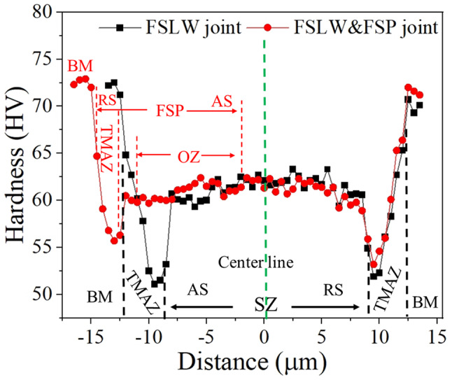
The microhardness profiles of FSLW and FSLW&FSP joints.
Tensile shear test results of FSLW and FSLW&FSP joints are shown in Fig. 12. Tensile fractures occurred at the upper side of both lap joints (FSLW and FSLW&FSP) (Fig. 12(a)) were observed during the tensile shear tests. The quasi-static shear tensile test results of both lap joints (Fig. 12(b and c)) show the tensile shear load of FSLW&FSP joint (219 ± 14.2 MPa) is significantly higher than that of FSLW joint (118.8 ± 9.1 MPa). It is also seen that the AA6061 FSLW joint processed by FSP indicates an improvement in the elongation. The tensile shear test comparison results of both AA6061 lap joints confirm that the microstructure reconstruction achieved by FSP is an effective method for increasing mechanical properties.
Fig. 12.
(a) broken FSLW joint and FSLW&FSP joint; (b) tensile shear-displacement curve; (c) comparison of tensile shear results.
The tensile fracture of FSLW and FSLW&FSP joints occurred at hook defect and TMAZ(FSP) by observing the cross sections of both broken joints (Fig. 13). Since the location of the hook defect in the AS of FSLW joint approximately coincides with its TMAZ, the EST thinning caused by hook defect (Fig. 4) and joint softening caused by TMAZ (Fig. 11) are the leading reason for the tensile failure of the FSLW joint. By contrast, the tensile strength of the FSLW&FSP joint is decided by the softened TMAZ(FSP) (Fig. 11) attributed to the dissolution of precipitates. Combined with the tensile shear test results of both lap joints, it can be concluded that the mechanical properties of TMAZ(FSP) of the FSLW&FSP joint are much higher than that of TMAZ at AS of the FSLW joint. The OZ(HS) with refined and equiaxed grains (Fig. 9(d)) formed by microstructure reconstruction of hook defect zone can achieve that the EST of the FSLW&FSP joint (Fig. 5(b)) is approximately equivalent to the thickness of as-received AA6061-T6, which is primarily responsible for the improvement of strength. Uniformly dispersed and refined precipitates can form a good bond with the substrate, which can improve the strength of BM51. Therefore, a lower degree of precipitate dissolution caused by lower heat input (Fig. 2) in TMAZ(FSP) of the FSLW&FSP joint (Fig. 11) is another reason for its higher tensile strength.
Fig. 13.
Cross sections of tensile shear fractured (a) FSLW joint and (b) FSLW&FSP joint.
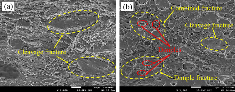
The SEM micrographs of tensile fracture surfaces of FSLW and FSLW&FSP joints are exhibited in Fig. 14. Several cleavage steps and river patterns characterizing brittle fracture were observed in the SEM image for the fracture surfaces of FSLW (Fig. 14(a)) and FSLW&FSP (Fig. 14(b)) joints. However, the cleavage plane of the fracture surface of the FSLW&FSP joint is much smaller than that of the FSLW joint. Besides, some dimples representing ductile fracture were also found in the fracture surfaces of the FSLW&FSP joint. Therefore, the fracture behavior of the FSLW&FSP joint consists of cleavage fracture and quasi-cleavage fracture that differs from the cleavage fracture of the FSLW joint. Besides, these results verified the higher toughness of AA6061 FSLW&FSP joints, which is consistent with the shear tensile test results of both lap joints.
Fig. 14.
SEM images of the tensile fractured specimens in the (a) FSLW and the (b) FSLW&FSP joints.
Conclusion
In this present study, FSP was used to eliminate the hook defect at the AS of the Al 6061-T6 FSLW joint. The effects of microstructure reconstruction caused by FSP on the appearance, microstructure, and mechanical properties of FSLW joints were discussed. The results of microstructure analysis showed that the hook defect area of the FSLW joint was reconstructed as the OZ(HS) of the FSLW&FSP joint. The EST of FSLW joints of Al alloys was improved by eliminating the hook defect under the action of FSP. Compared with the hook defect zone of the FSLW joint with course and unevenly sized grains, the OZ(HS) of the FSLW&FSP joint was characterized by refined and equiaxed grains due to the dynamic recrystallization. The local stress concentration of the OZ(HS) of the FSLW&FSP joint was significantly lower than that of the hook defect zone of the FSLW joint as a result of microstructure homogenization. The mechanical performance analysis results showed that the hardness, tensile shear strength, and toughness of the FSLW&FSP joint were significantly higher than those of the FSLW joint. The failure location of the lap joint changed from the hook defect at the AS of the FSLW joint to the TMAZ(FSP) at the FSLW&FSP joint. Therefore, it can be concluded that the enhancement of mechanical properties of the FSLW&FSP joint is attributed to the combined results of EST improvement by hook defect elimination, local stress concentration reduction, and a lower degree of precipitate dissolution at TMAZ(FSP).
Acknowledgements
Financial support by Liaoning University of Technology under contract number the XB2023006, Liaoning Province Education Department under contract number No. JYTQN2023223, and Scientific and Technological Department of Liaoning Province under contract number No. 2024-BS-238 is gratefully acknowledged by all authors. This work was also supported by Anhui Polytechnic University. Prof. Sung-Tae Hong, School of Mechanical Engineering, University of Ulsan, was acknowledged for providing partial experimental and testing facilities throughout this research work.
Author contributions
Kun Gao conceived the idea of the paper, implemented the experiments, and wrote the main manuscript text; Zhenlong Zhang prepared Figs. 1, 2, 3, 4 and 5; Guangdong Wang prepared Figs. 6, 7, 8 and 9, and 10; Xiaojun Sun prepared Fig. 11, and 12; Yingyue Zhang prepared Figs. 13 and 14. All authors reviewed the manuscript.
Funding
This work was supported by 2024 Fundamental Research Project (No. 2024-BS-238) of the Scientific and Technological Department of Liaoning Province, the 2023 Doctoral Research Initiation Fund Program (XB2023006), and 2023 Fundamental Research Project (No. JYTQN2023223) of the Educational Department of Liaoning Province.
Data availability
The research data used or analysed during the current study are available from the corresponding author on reasonable request.
Declarations
Competing interests
The authors declare no competing interests.
Footnotes
Publisher’s note
Springer Nature remains neutral with regard to jurisdictional claims in published maps and institutional affiliations.
References
- 1.Hannan, M. A., Azidin, F. A. & Mohamed, A. Hybrid electric vehicles and their challenges: a review. Renew. Sustain. Energy Rev.29, 135–150. 10.1016/j.rser.2013.08.097 (2014). [Google Scholar]
- 2.Zhang, C., Huang, G., Zhang, D., Sun, Z. & Liu, Q. Microstructure and mechanical properties in dissimilar friction stir welded AA2024/7075 joints at high heat input: effect of post-weld heat treatment. J. Mater. Res. Technol.9, 14771–14782. 10.1016/j.jmrt.2020.10.053 (2020). [Google Scholar]
- 3.Abdollahzadeh, A., Shokuhfar, A., Cabrera, J. M., Zhilyaev, A. P. & Omidvar, H. The effect of changing chemical composition on dissimilar Mg/Al friction stir welded butt joints using zinc interlayer. J. Manuf. Process.34, 18–30. 10.1016/j.jmapro.2018.05.029 (2018). [Google Scholar]
- 4.Basak, S. et al. Friction stir butt-welding of Roll cladded Aluminum thin sheets: Effect of Microstructural and texture changes on Mechanical Properties. Adv. Mater. Sci. Eng.832, 142490. 10.1016/j.msea.2021.142490 (2022). [Google Scholar]
- 5.Gao, K. et al. Friction stir welding of AA3003-clad AA6013 thin sheets: Microstructural Changes related to Tensile properties and fatigue failure mechanism. J. Mater. Res. Technol.17, 3221–3233. 10.1016/j.jmrt.2022.02.073 (2022). [Google Scholar]
- 6.Hasanniah, A. & Movahedi, M. Welding of Al-Mg aluminium alloy to aluminium clad steel sheet using pulsed gas tungsten arc process. J. Manuf. Process.31, 494–501. 10.1016/j.jmapro.2017.12.008 (2018). [Google Scholar]
- 7.Gao, K. et al. Friction stir spot butt welding of dissimilar S45C steel and 6061-T6 aluminum alloy. Metals11, 1252. 10.3390/met11081252 (2021). [Google Scholar]
- 8.Leal, R. M. & Loureiro, A. Effect of overlapping friction stir welding passes in the quality of welds of aluminium alloys. Mater. Des.29, 982–991. 10.1016/j.matdes.2007.03.018 (2008). [Google Scholar]
- 9.Yuqing, M. et al. Achieving high-performance FSLW AZ31B/TC4 dissimilar joints with ultrastrong interface by Sn addition. J. Magnes Alloy. 10.1016/j.jma.2024.07.007 (2024). [Google Scholar]
- 10.Yuqing, M. et al. Improving tensile-shear properties of friction stir lap welded dissimilar Al/Mg joints by eliminating hook defect and controlling interfacial reaction. Chin. J. Aeronaut.36 (7), 257–267. 10.1016/j.cja.2022.11.026 (2023). [Google Scholar]
- 11.Yadava, M. K., Mishra, R. S., Chen, Y. L., Carlson, B. & Grant, G. J. Study of friction stir joining of thin aluminium sheets in lap joint configuration. Sci. Technol. Weld. Joi. 15, 70–75. 10.1179/136217109x12537145658733 (2010). [Google Scholar]
- 12.Yuan, W., Carlson, B., Verma, R. & Szymanski, R. Study of top sheet thinning during friction stir lap welding of AZ31 magnesium alloy. Sci. Technol. Weld. Joi. 17 (5), 375–380. 10.1179/1362171812y.0000000018 (2012). [Google Scholar]
- 13.Mao, Y. Q. et al. Improving tensile-shear properties of friction stir lap welded dissimilar Al/Mg joints by eliminating hook defect and controlling interfacial reaction. Chin. J. Aeronaut.36 (7), 257–267. 10.1016/j.cja.2022.11.026 (2023). [Google Scholar]
- 14.Liu, H. J., Hu, Y. Y., Peng, Y. X., Dou, C. & Wang, Z. G. The effect of interface defect on mechanical properties and its formation mechanism in friction stir lap welded joints of aluminum alloys. J. Mater. Process. Tech.238, 244–254. 10.1016/j.jmatprotec.2016.06.029 (2016). [Google Scholar]
- 15.Xu, X., Yang, X., Zhou, G. & Tong, J. Microstructures and fatigue properties of friction stir lap welds in aluminum alloy AA6061-T6. Mater. Des.35, 175–183. 10.1016/j.matdes.2011.09.064 (2012). [Google Scholar]
- 16.Fersini, D. & Pirondi, A. Analysis and modelling of fatigue failure of friction stir welded aluminum alloy single-overlap joints. Eng. Fract. Mech.75, 790–803. 10.1016/j.engfracmech.2007.04.013 (2008). [Google Scholar]
- 17.Kulekci, M. K., Şik, A. & Kaluç, E. Effects of tool rotation and pin diameter on fatigue properties of friction stir welded lap joints. Int. J. Adv. Manuf. Tech.36 (9–10), 877–882. 10.1007/s00170-006-0901-z (2006). [Google Scholar]
- 18.Buffa, G., Campanile, G. & Fratini, L. Prisco, A. Friction stir welding of lap joints: influence of process parameters on the metallurgical and mechanical properties. Mater. Sci. Eng. Struct.519, 19–26. 10.1016/j.msea.2009.04.046 (2009). [Google Scholar]
- 19.Yue, Y. M., Li, Z. W., Ji, S. D., Huang, Y. X. & Zhou, Z. L. Effect of reverse-threaded pin on Mechanical properties of Friction stir Lap Welded Alclad 2024 Aluminum Alloy. J. Mater. Sci. Technol.32 (7), 671–675. 10.1016/j.jmst.2016.03.005 (2016). [Google Scholar]
- 20.Costa, M. I., Verdera, D., Costa, J. D., Leitao, C. & Rodrigues, D. M. Influence of pin geometry and process parameters on friction stir lap welding of AA5754-H22 thin sheets. J. Mater. Process. Tech.225, 385–392. 10.1016/j.jmatprotec.2015.06.020 (2015). [Google Scholar]
- 21.Yazdanian, S., Chen, Z. W. & Littlefair, G. Effects of friction stir lap welding parameters on weld features on advancing side and fracture strength of AA6060-T5 welds. J. Mater. Sci.47, 1251–1261. 10.1007/s10853-011-5747-6 (2012). [Google Scholar]
- 22.Shirazi, H., Kheirandish, S. H. & Safarkhanian, M. A. Effect of process parameters on the macrostructure and defect formation in friction stir lap welding of AA5456 aluminum alloy. Measurement76, 62–69. 10.1016/j.measurement.2015.08.001 (2015). [Google Scholar]
- 23.Liyakat, N. A. & Veeman, D. Improvement of mechanical and microstructural properties of AA 5052-H32 TIG weldment using friction stir processing approach. J. Mater. Res. Technol.19, 332–344. 10.1016/j.jmrt.2022.05.015 (2022). [Google Scholar]
- 24.Abdollahzadeh, A., Shokuhfar, A., Cabrera, J. M., Zhilyaev, A. P. & Omidvar, H. In-situ nanocomposite in friction stir welding of 6061-T6 aluminum alloy to AZ31 magnesium alloy. J. Mater. Process. Tech.10.1016/j.jmatprotec.2018.08.025 (2018). S0924013618303674. [Google Scholar]
- 25.Gao, K. et al. Effect of Microstructural Changes by Friction stir Processing on the clad-to-core interfacial strength of thin aluminum-clad aluminum sheets. Met. Mater. Int.10.1007/s12540-024-01776-9 (2024). [Google Scholar]
- 26.Das, H. et al. Microstructure and mechanical properties evaluation of friction stir welded boron steel. J. Mech. Sci. Technol.34 (5), 2011–2017. 10.1007/s12206-020-0422-y (2020). [Google Scholar]
- 27.Mondal, M. et al. Characterization of Friction Stir Welded Joint of Low Nickel Austenitic Stainless Steel and Modified Ferritic Stainless Steel. Met. Mater. Int.23 (5), 948–957. 10.1007/s12540-017-6845-z (2017). [Google Scholar]
- 28.Abdollahzadeh, A., Bagheri, B., Vaneghi, A. H., Shamsipur, A. & Mirsalehi, S. E. Advances in simulation and experimental study on intermetallic formation and thermomechanical evolution of Al–Cu composite with zn interlayer: Effect of spot pass and shoulder diameter during the pinless friction stir spot welding process. P I Mech. Eng. L -J Mat.237 (6), 1475–1494. 10.1177/14644207221146981 (2023). [Google Scholar]
- 29.Gao, K. et al. Effects of the microstructure on the fatigue fracture of friction stir lap welded Al-clad Al and Al-clad steel sheets. J. Mater. Res. Technol.22, 2518–2531. 10.1016/j.jmrt.2022.12.103 (2023). [Google Scholar]
- 30.Li, J. Q. & Liu, H. J. Effects of tool rotation speed on microstructures and mechanical properties of AA2219-T6 welded by the external non-rotational shoulder assisted friction stir welding. Mater. Des.43, 299–306. 10.1016/j.matdes.2012.07.011 (2013). [Google Scholar]
- 31.Wu, M., Wu, C. S. & Gao, S. Effect of ultrasonic vibration on fatigue performance of AA 2024-T3 friction stir weld joints. J. Manuf. Process.29, 85–95. 10.1016/j.jmapro.2017.07.023 (2017). [Google Scholar]
- 32.Costa, M. I., Verdera, D., Costa, J. D., Leitao, C. & Rodrigues, D. M. Influence of pin geometry and process parameters on friction stir lap welding of AA5754-H22 thin sheets. J. Mater. Process. Tech.225, 385–392. 10.1016/j.jmatprotec.2015.06.020 (2015). [Google Scholar]
- 33.Sachindra, S., Kanhaiya, S., Somnath, C. & Sergej, H. Investigation on Different Type of Defects, Temperature Variation and Mechanical Properties of Friction Stir Welded Lap joint of Aluminum Alloy 6101-T6. Mater. Today. Proc. 5(11), 24378–24386. (2018). 10.1016/j.matpr.2018.10.233
- 34.Zhao, P. C., Shen, Y. F., Huang, G. Q. & Zheng, Q. X. Numerical simulation of friction stir butt-welding of 6061 aluminum alloy. T Nonferr Metal Soc.28 (6), 1216–1225. 10.1016/S1003-6326(18)64759-4 (2018). [Google Scholar]
- 35.Pankaj, P., Tiwari, A., Dhara, L. N. & Biswas, P. Multiphase CFD simulation and experimental investigation of friction stir welded high strength shipbuilding steel and aluminum alloy. Cirp J. Manuf. Sci. Tec.39, 37–69. 10.1016/j.cirpj.2022.07.001 (2022). [Google Scholar]
- 36.Zou, S. et al. Multi-track friction stir lap welding of 2024 aluminum Alloy: Processing, microstructure and Mech Properties. Metals7 (1), 1. 10.3390/met7010001 (2017). [Google Scholar]
- 37.Salih, O. S., Ou, H. & Sun, W. Heat generation, plastic deformation and residual stresses in friction stir welding of aluminium alloy. Int. J. Mech. Sci.238, 107827. 10.1016/j.ijmecsci.2022.107827 (2023). [Google Scholar]
- 38.Song, Y. et al. Defect features and mechanical properties of friction stir lap welded dissimilar AA2024–AA7075 aluminum alloy sheets. Mater. Des.55, 9–18. 10.1016/j.matdes.2013.09.062 (2014). [Google Scholar]
- 39.Dubourg, L., Merati, A. & Jahazi, M. Process optimisation and mechanical properties of friction stir lap welds of 7075-T6 stringers on 2024-T3 skin. Mater. Des.31, 3324–3330. 10.1016/j.matdes.2010.02.002 (2010). [Google Scholar]
- 40.Tucci, F., Carlone, P., Silvestri, A. T., Parma, H. & Astarita, A. Dissimilar friction stir lap welding of AA2198-AA6082: process analysis and joint characterization. Cirp J. Manuf. Sci. Tec.35, 753–764. 10.1016/j.cirpj.2021.09.007 (2021). [Google Scholar]
- 41.Babu, S., Janaki Ram, G. D., Venkitakrishnan, P. V., Reddy, G. M. & Prasad Rao, K. Microstructure and Mechanical properties of Friction stir Lap Welded Aluminum Alloy AA2014. J. Mater. Sci. Technol.28 (5), 414–426. 10.1016/S1005-0302(12)60077-2 (2012). [Google Scholar]
- 42.Okamura, H., Aota, K., Sakamoto, M., Ezumi, M. & Ikeuchi, K. Behavior of oxide during friction stir welding of aluminum alloy and its influence on mechanical properties. Q. J. Jpn Weld. Soc.19, 446–456. 10.2207/qjjws.19.446 (2001). [Google Scholar]
- 43.Hu, Y. Y., Liu, H. J., Li, S., Du, S. S. & Sekulic Dusan, P. Improving mechanical properties of a joint through tilt probe penetrating friction stir welding. Adv. Mater. Sci. Eng.731, 107–118. 10.1016/j.msea.2018.06.036 (2018). [Google Scholar]
- 44.Rajendran, C., Srinivasan, K., Balasubramanian, V., Balaji, H. & Selvaraj, P. Effect of tool tilt angle on strength and microstructural characteristics of friction stir welded lap joints of AA2014-T6 aluminum alloy. T Nonferr Metal Soc.29 (9), 1824–1835. 10.1016/S1003-6326(19)65090-9 (2019). [Google Scholar]
- 45.Ahmed, K. S., Toshiya, S. & Masaaki, N. Microstructure and Mechanical properties of Friction stir welded AA2024-T3 aluminum Alloy. Mater. Trans.47 (1), 185–193. 10.2320/matertrans.47.185 (2006). [Google Scholar]
- 46.Hu, Y. Y., Liu, H. J., Li, S., Du, S. & Sekulic, D. P. Improving mechanical properties of a joint through tilt probe penetrating friction stir welding. Adv. Mater. Sci. Eng.731, 107–118. 10.1016/j.msea.2018.06.036 (2018). [Google Scholar]
- 47.Abdollahzadeh, A. et al. Comparison of the weldability of AA6061-T6 Joint under different friction stir welding conditions. J. Mater. Eng. Perform.30, 1110–1127. 10.1007/s11665-020-05379-4 (2021). [Google Scholar]
- 48.Rodrigues, D. M. et al. Influence of friction stir welding parameters on the microstructural and mechanical properties of AA 6016-T4 thin welds. Mater. Des.30 (6), 1913–1921. 10.1016/j.matdes.2008.09.016 (2009). [Google Scholar]
- 49.El-Rayes, M. M. & El-Danaf, E. A. The influence of multi-pass friction stir processing on the microstructural and mechanical properties of Aluminum Alloy 6082. J. Mater. Process. Tech.212 (5), 1157–1168. 10.1016/j.jmatprotec.2011.12.017 (2012). [Google Scholar]
- 50.Wang, X. B. & Lados, D. A. Optimization of aluminum-to-steel friction stir lap welding for the fabrication of high-integrity structural components. J. Adv. Join. Process.5, 100114. 10.1016/j.jajp.2022.100114 (2022). [Google Scholar]
- 51.Abdolahzadeh, A. et al. Studying microstructure and mechanical properties of SiC-incorporated AZ31 joints fabricated through FSW: the effects of rotational and traveling speeds. Int. J. Adv. Manuf. Technol.75, 1189–1196. 10.1007/s00170-014-6205-9 (2014). [Google Scholar]
Associated Data
This section collects any data citations, data availability statements, or supplementary materials included in this article.
Data Availability Statement
The research data used or analysed during the current study are available from the corresponding author on reasonable request.


