Abstract
As many oil and gas reservoirs approach depletion stages in the future, alongside growing energy storage demands, constructing gas storage facilities becomes critical for ensuring a stable natural gas supply. Consequently, a comprehensive geological analysis is essential to evaluate the feasibility of converting depleted gas reservoirs into gas storage facilities. The W gas reservoir in the Sichuan Basin, China, is nearing depletion and presents potential for conversion into a gas storage facility. This study provides a comprehensive geological evaluation to determine its feasibility for such conversion. Exploration and production data indicate that the W gas reservoir is a pore-fracture type carbonate reservoir. Vertically, the sub-layer beneath C2hl2 demonstrates the best physical properties. Horizontally, the area enclosed by wells C30, C10, and C18 exhibits favorable reservoir characteristics. The reservoir’s caprock comprises a superimposed composite system, including the direct caprock of the Liangshan Formation and an overlying ultra-thick dense rock layer, which is extensive and exhibits high breakthrough pressure. Nine major faults control the structural trap’s shape and scale. These faults, in a compressive state, are well-sealed due to fault gouge, enhancing their closure. The reservoir space is primarily pore-fracture type, and rapid injection and withdrawal induce minimal pressure changes, indicating low stress sensitivity. The comprehensive evaluation concludes that the Carboniferous gas reservoir possesses favorable geological conditions, making it suitable for conversion into a gas storage facility. This study offers a preliminary geological evaluation of the feasibility of converting fault-controlled fracture-type carbonate reservoirs into gas storage facilities and outlines directions for future research.
Keywords: The Wanshunchang structure, Carboniferous gas reservoirs, Gas storage, Closure property, Comprehensive geological analysis
Subject terms: Sedimentology, Petrology
Introduction
Underground natural gas storages, similar to “artificial gas reservoirs,” are major facilities for ensuring supplies during peak usage of natural gas1. Traditional oil and gas reservoirs are often developed utilizing depletion production, where formation pressure changes from high to low unidirectionally. In contrast, in the development of gas storages, formation pressure changes with the rapid injection-exhaust of natural gas. The unique pattern of “high-throughput” rapid injection production during operation inevitably leads to changes in multiple parameters in the geological bodies of gas storage sites. This explains why natural gas storage sites, compared with traditional oil and gas reservoirs, have higher requirements regarding site selection and construction in the preliminary stage and operation and maintenance during service. Converting a depleted gas reservoir into gas storage requires evaluating the geological feasibility of conversion, the geological analysis results have an impact on the evaluation of other parameters (such as the gas storage capacity and the number of injection-production wells)2,3.
The Wanshunchang gas reservoir (hereinafter referred to as “the W gas reservoir”) in the Sichuan Basin, China, is nearing depletion and has the potential for conversion into a gas storage facility. This study provides a comprehensive geological evaluation to assess its feasibility for such conversion. Numerous studies have been performed on the geological feasibility of converting oil and gas reservoirs into gas storage sites. However, these studies mainly focus on the analysis of individual factors. They generally address four aspects: the gas reservoir profile, caprock sealing properties, fault sealing properties, and reservoir stress sensitivity under alternating stress conditions4–6. Despite this, there is a lack of comprehensive geological research dedicated to investigating the conversion of depleted carbonate gas reservoirs into underground gas storage sites. In this study, exploration and development data of the W gas reservoir were collected and analyzed. The thickness, regional distribution, and sedimentary environments of the direct and indirect trap caprocks were quantitatively analyzed at the micro level during caprock evaluation. At the micro level, the mechanical integrity, capillary sealing properties, and breakthrough pressure of caprocks were quantitatively assessed through laboratory tests7–15. Geological, seismic, and logging data were comprehensively interpreted to analyze fault-sealing properties both qualitatively and quantitatively16–23. Reservoir stress sensitivity was investigated due to the repeated changes in formation pressure caused by gas injection and withdrawal. In the laboratory, changes in the physical properties of reservoir cores were observed under artificially simulated cyclic formation pressure changes24–26.
Therefore, this study conducted a comprehensive geological analysis to evaluate the feasibility of converting a Carboniferous gas reservoir in the W block of the Sichuan Basin into underground gas storage. The analysis focused on the sedimentary features, structural traps, caprock sealing efficiency, fault sealing capacity, and reservoir stress sensitivity of carbonate gas reservoirs. This study confirms the geological viability of this conversion and aims to provide a theoretical foundation for transforming porous-fractured carbonate reservoirs into gas storage sites.
Geologic framework
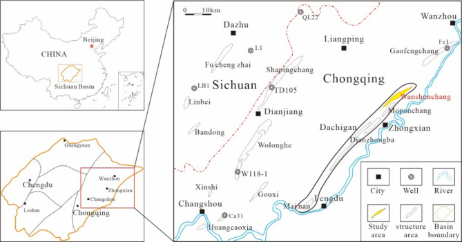
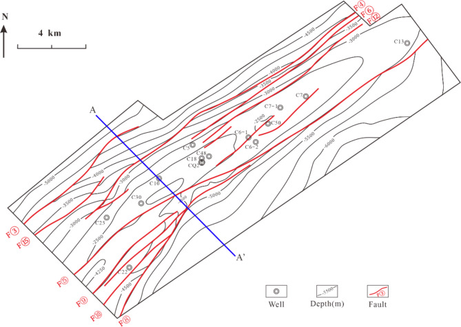
Geographically, the W gas reservoir is located in Chongqing, about 20 km from Zhongxian County in the southwest and 70 km from Liangping County in the northwest. Tectonically, it belongs to the eastern Sichuan high-steep structural belt and is a secondary structure in the northeast Dachigan structural belt. As a NEE–SWW elongated anticline with fault development, it is gentle on the NW wing, flat at the apex, and steep in the SE wing (Fig. 1). The Wanshunchang structure (hereinafter referred to as “the W structure “) has nine major faults which control the shapes and scales of structural traps. Fault F⑤ in the middle-southern segment cuts through the axis of the W structure and controls its SE wing. Faults F③ and F⑮ are located in the northwest. Faults F④, F⑪, and F⑫ are located in the middle and northeast. Faults F⑨ and F⑩ control the trap range at the anticlinal high point of Mopanchang. Fault F⑬ cuts through the top of the structure. These faults are reverse faults that strike almost parallel to the axial direction of the structure and control their local structures (Fig. 2). The anticlinal high point has an elevation of -2,270 m, a closure height of 330 m, and a closure area of 25.81 km2.
Fig. 1.
Location map of the W gas reservoir.
Fig. 2.
Structural map of the Carboniferous top surface of the W gas reservoir.
The exploitation of the Carboniferous gas reservoir began in September 1987. It had an original formation pressure of 38.5 MPa, and a pressure coefficient of 1.21. Its gas-water table was located at -2,606 m below the surface (well C7), and the energy level of edge-bottom water was low. As of 2018, the gas reservoir had entered a low-production stage, with cumulative gas production of 59.29 × 10⁸ m3 since 1987.
Data and methods
This study conducted a comprehensive analysis of the stratigraphic division and sedimentological characteristics of the W gas field. Methods included well-logging data interpretation, mud-logging data analysis, core observation, and thin section identification. The structural characteristics of the W gas field were assessed using drilling and seismic data, with quantitative evaluations of fault sealing coefficients and the shale gouge ratio (SGR) of fault rocks based on seismic data. Reservoir and cap rock properties were analyzed using core sample physical property tests, oil well production data, and gas logging data.
The well-logging data, mud-logging data, seismic data, and production data used in this study were provided by Sichuan Petroleum Management Bureau Co., Ltd., a subsidiary of China National Petroleum Corporation. At the Sedimentary Basin Experimental Center of Yangtze University (Wuhan, China), 30 μm-thick rock thin sections were prepared from core samples. A research-grade intelligent transmitted polarized light microscope (Leica DM4P upright polarizing microscope, Leica Microsystems (Shanghai) Trading Co., Ltd.) was used for detailed sedimentological and petrological analyses of all thin sections. The rock particle size classification scheme is presented in Table 1. Reservoir stress sensitivity tests were performed on core samples at the Key Laboratory of Oil and Gas Underground Storage, China National Petroleum Corporation (Langfang, China), in compliance with the industry standards established by the National Energy Administration of China (SY/T 5358–2010).
Table 1.
Classification of grain sizes used.
| Grain size, mm | Carbonate intraclasts | Carbonate grains |
|---|---|---|
| >2.0 | Rubble | Gravel crystal |
| 0.25–2.0 | Arene | Sand crystal |
| 0.05–0.25 | Sludge | Powder crystal |
| <0.05 | Mud-sized grain | Micrite |
Stratigraphic division and sedimentary characteristics
The Carboniferous formation in the study area has disconformable contacts with both the overlying Permian Liangshan Formation and the underlying Middle Silurian Hanjiadian Formation. There is no Lower Carboniferous Hezhou Formation in the study area, and only some formations of the Upper Carboniferous Huanglong Formation remain. The formations of the Huanglong Formation are, in ascending order, the first Huanglong Member (C2hl1), the second Huanglong Member (C2hl2), and the third Huanglong Member (C2hl3). C2hl3 is eroded in the study area, and only incomplete C2hl1 and C2hl2 remain in these wells. The residual thickness is 18.5 m ~ 40 m, 28.7 m on average. Horizontally, the formations gradually thicken from south to north. C2hl2 is further subdivided into three Sub-members in ascending order: C2hl21, C2hl22, and C2hl23.
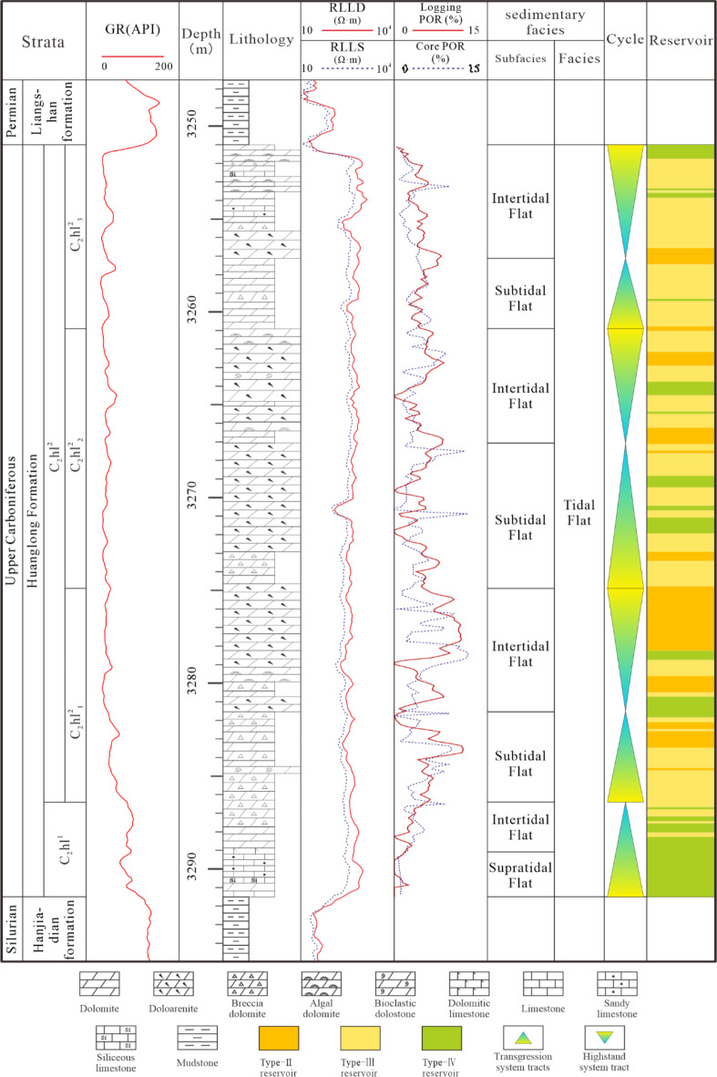
There are still controversies over the characteristics of the sedimentary facies in the study area. Some have suggested that these formations were deposited in a bay tidal flat–open subtidal sedimentary system limited by barriers27, a sabkha–barrier coast–bay continental shelf sedimentary system28,29, or in a carbonate tidal flat–shallow-sea continental shelf sedimentary system30. By combining previous studies and existing data, this study concluded that the Huanglong Formation was deposited in a tidal flat within a restricted bay, which can be further subdivided into supratidal flat, intertidal flat, and subtidal flat (Fig. 3). C2hl1 was primarily deposited in a supratidal flat environment, characterized by compact lithology. C2hl2 was mostly deposited in intertidal and subtidal flat environments, with extensive dissolution caves and fractures, and the physical properties of the reservoir are excellent. Generally, the porosity of the transgressive systems tract is slightly low, while that of the highstand systems tract is relatively high (Fig. 3).
Fig. 3.
Columnar section of Well C7 in the W block.
Reservoir characteristics
Petrological characteristics
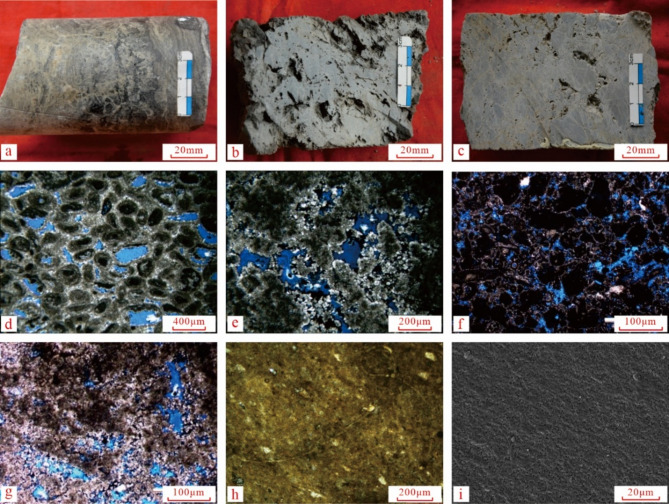
The lithology of Carboniferous Member C2hl1 in the W block is dominated by fine crystalline secondary limestone (Fig. 4a), which is relatively compact. Member C2hl2, being a primary reservoir, has widespread dissolution caves and fractures (Fig. 4b and c). The lithology of its three Sub-members is as follows: (1) Sub-member C2hl21 is mainly composed of fine-crystalline dolomite and particle dolomite; (2) Sub-member C2hl22 is composed of particle dolomite and breccia dolomite; (3) Sub-member C2hl23 is composed of fine-crystalline dolomite and particle dolomite, which are mingled with breccia limestone locally (Fig. 4).
Fig. 4.
Reservoir and caprock characteristics of the W gas reservoir. Note: (a) fine crystalline secondary limestone (C16 Well, C2hl2, 3447.26–3447.44 m); (b) brownish gray dissolved pore-like algal doloarenite (C25 Well, C2hl2, 3271.02–3271.12 m); (c) brownish gray dissolved pore-like breccia dolomite (C16 Well, C2hl2, 3429.07–3429.24 m); (d) doloarenite, intergranular pores(C7 Well, C2hl2 ,3269.9 m); (e) algal dolomite, intergranular dissolved pores(C7 Well, C2hl2 ,3272.9 m); (f) doloarenite, intergranular dissolved pores and intragranular pores(C25 Well, C2hl2 ,3276 m); (g) algal dolomite, intergranular dissolved pores and intercrystalline pores(C25 Well, C2hl2 ,3292.9 m); (h) casting thin sections from the caprock of the adjacent Liangshan Formation, with compact lithology XC10 Well, Liangshan Formation); (i) SEM image of the caprock of the adjacent Liangshan Formation, with compact lithology(XC10 Well, Liangshan Formation).
Physical properties
According to the statistics of the porosity analysis results of the 756 core samples, the Carboniferous gas reservoirs have porosity ranges from 0.39 to 16.96% and an average porosity of 4.73%. To be specific, Type-I reservoirs with a porosity of ≥ 12% only account for 6.3% of the section; Type-II reservoirs with a porosity of 6–12% account for 22.4%; Type-III reservoirs with a porosity of 2.5–6% account for 34.1% of the total section; and Type-IV reservoirs (non-reservoirs) with a porosity of below 2.5% account for 37.2%. The wells with the most well-developed pores are C25 (6.78% on average) and C30 (6.52% on average); those with the least well-developed pores are C7 (3.80% on average) and C16 (3.61% on average) (Fig. 5a; Table 2).
Fig. 5.
Histogram of physical reservoir properties of the W gas reservoir.
According to the 439 effective permeability data points analysis, the matrix permeability of the W gas reservoir is generally low, ranging from 0 to 233.69 mD and an average of 4.66 mD. Samples with a matrix permeability of below 0.01 mD account for 38.72% of the samples; those with a matrix permeability of 0.01–0.1 mD account for 6.15%; those with a matrix permeability of 0.1–1 mD account for 21.18%; those with a matrix permeability of 1–10 mD account for 25.28%; and those with a matrix permeability of above 10 mD account for 8.66% (Fig. 5b). Seen from the statistics of Type-I, Type-II, and type-III reservoirs, overall, there is a trend of increase in matrix permeability with increasing porosity.
Table 2.
Classification of reservoirs.
| Properties | Type of reservoirs |
|---|---|
| >12% | Type-I |
| 12%~6% | Type-II |
| 6%~2.5% | Type-III |
| <2.5 | Type-IV |
According to the statistics of the 543 water saturation samples in the W gas reservoir, the average water saturation range of the gas wells is 14.13–20.82%, with an average of 57.94%. According to the statistics of the core samples collected from gas wells C30, C10, C50, and C7 for physical property analysis, the water saturation of gas wells in the Carboniferous gas reservoir is most frequently distributed between “<20%” and “20%~40%” (Fig. 5c).
The anticlinal high and axis are characterized by fine porosity and permeability and high gas saturation, with a porosity above 7% in most cases (even as high as 8.33–8.61%). The gas saturation of Wellblock C5-C10-C18 is generally above 80% and may exceed 85% in some cases (Wellblock C30). In previous well tests, Well C18 has the strongest permeability interpretability (105mD), while Well C50 has the weakest (3.23mD). The Carboniferous gas reservoir generally has good physical reservoir properties and is a high-permeability reservoir.
Distribution characteristics
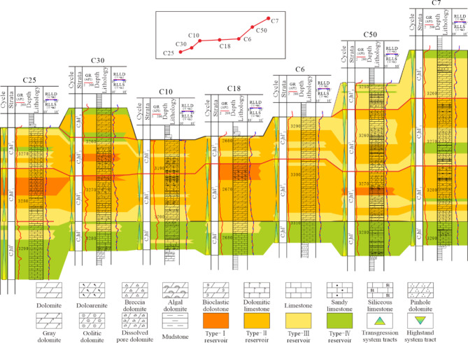
Poressity differs significantly in degree of development across different wells, but it obeys apparent distribution trends. Vertically, reservoirs are mainly distributed in C2hl2 (5.6% on average), while C2hl1 contains few reservoirs (1.2% on average). The cycles of C2hl2 also differ from each other vertically. Sub-member 1# (C2hl21) has the most well-developed pores, with an average porosity of 6.2%. The average porosities of Sub-member 2# (C2hl22) and Sub-member 3# (C2hl23) are 5.1% and 2.6%, respectively. Overall, pores increase with depth (Fig. 6).
Fig. 6.
Comparison of Carboniferous well-tie reservoirs in the W gas reservoir.
The algal sand flat microfacies, algal dolomitic flat microfacies, and subtidal flat fragmental shoal microfacies of the intertidal flat subfacies of C2hl2 have the highest average porosities, i.e., 8.04%, 7.94%, and 6.8%, respectively. The supratidal flat reservoirs, mainly distributed in C2hl1, have the poorest physical properties, with an average porosity lower than the effective porosity (2.5%).
Based on the porosity data from the logging interpretation of individual wells and the porosity data from core porosity tests, statistics were calculated on the cumulative thickness of the effective reservoir sections that had a porosity of above 2.5% for each well. Horizontally, the area with the highest average effective porosity in the W gas reservoir is located in Wellblock C30-C10-C18. The greatest is in Wellblock C18 (with an average porosity of 8.8%), followed by Wellblock C50. Wellblock C6-1 is between the two above wells (Fig. 7a). On the whole, the distribution trends of the effective reservoir thickness are similar to those of average porosity. To be specific, Wellblock C50-C7 has the most considerable effective reservoir thickness (30.3 m for Well C7 and 25.4 m for Well C50), followed by Wellblock C30-C10-C18 (16.3–19.4 m). The effective reservoir thicknesses of other areas are all below 12 m. Notably, Well C6-1 has the lowest effective reservoir thickness (Fig. 7b).
Fig. 7.
Horizontal distribution map of the W gas reservoir.
Feasibility evaluation
Caprock sealing property evaluation
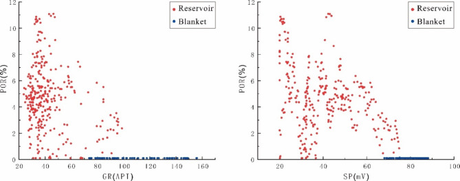
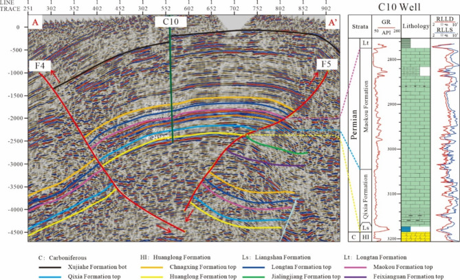
Macroscopically, the overlying formation of the W gas reservoir is composed of the shale of the Lower Permian Liangshan Formation. It is widely distributed in the area with a general thickness of above 8.0 m and constitutes an effective direct caprock. According to the logging data analysis, there is a strong correlation between logging porosity (POR) and the gamma ray (GR) curve 31–33 (Fig. 8). Taking Well C7 in the study area as an example, when the GR value exceeds 70 API and the spontaneous potential (SP) curve value exceeds 68 mV, logging porosity is generally less than 0.1%. However, the GR data of the Liangshan Formation range between 80 and 156 API, and the SP data range between 70 and 87 mV, indicating that the caprock of the Liangshan Formation has low porosity and high clay content. In addition, the overlying Qixia Formation–Leikoupo Formation formations are compact carbonate and mudstone (shale), which are greater than 100 m in thickness and stably distributed in the area and can serve as an indirect caprock. This composite caprock system further strengthens the sealing ability of the W gas reservoir (Fig. 9).
Fig. 8.
Porosity vs. logging data for Well C7.
Fig. 9.
Seismic section showing the structure and caprock distribution characteristics of the W gas reservoir.
The analysis and testing data of the adjacent area (the Xiangguosi Carboniferous gas storage) is used as a reference due to the absence of coring data on the caprock in the study area. The core of the Liangshan Formation of the direct caprock is highly compact as a whole (Fig. 4e), and there are no visible pores under a resolution of 13 μm from the thin section SEM image of the caprock (Fig. 4f). The specific surface area is 2.129–3.691 m2/g. The rock samples from the Liangshan Formation have a porosity range of 0.07–0.63% and a permeability range of 0.0017–0.0029 mD, both of which reflect the compactness of rocks. The ranges of displacement pressure, maximum pore-throat radius, breakthrough pressure, and extreme operating pressure are 26.23–29.85 MPa, 0.252–1.186 μm, 32.4–37.6 MPa, and 55.7–61 MPa, respectively.
The Liangshan Formation is characterized by narrow pore-throats, small pore-throat radius, high displacement pressure, and a strong ability to seal natural gas. According to the grading criteria on the porosity-permeability characteristics of gas storage sites converted from depleted oil and gas reservoirs20, the mud shale of the overlying Liangshan Formation and Longtan Formation of the Carboniferous gas reservoir has a strong ability to seal natural gas, and constitutes a high-quality caprock.
Fault sealing evaluation
(1) Qualitative analysis
After comprehensive considerations of the evaluation indices commonly used in qualitative research on fault sealing properties and the realities of the study area21, this study selected four indices as evaluation parameters: fault occurrence, fault nature, combination feature, and upper/lower plate configuration relationship.
Fault occurrence: The strikes of the major faults of the traps in the study area are all nearly perpendicular to the direction of the maximum horizontal principal stress, which gives rise to the best type of occurrence in terms of sealing property.
Fault nature: The faults in the study area are all compresso-shear faults with good sealing capacity.
Combination feature: The formation dip in the study area is opposite to the fault dip, which produces a reverse combination relationship and is conducive to fault sealing.
Upper/lower plate configuration relationship: The upper-plate Carboniferous system of major fault F⑤ corresponds to the compact carbonate + gypsum rock layer in the lower-plate Jialingjiang Formation. The upper-plate Carboniferous system of fault F④ corresponds to the black shale + limestone layer in the lower-plate Longtan Formation. The other minor faults at the top correspond to the black shale + coal layer in the lower-plate Liangshan Formation. Overall, all the faults in the study area have a good sealing property (Fig. 9).
(2) Quantitative analysis.
Given the realities of the study area (such as the small number of wells in the working area, the absence of coring data on the fault zones, and the lack of pressure test data), this study selected fault sealing coefficient and fault-plane mudstone smearing analysis for evaluation.
The fault sealing coefficient is a parameter used to evaluate the oil and gas sealing ability of the two plates of a fault plane. A larger fault sealing coefficient indicates a stronger sealing ability. A fault sealing coefficient of > 15 means that the fault is essentially seals.
The calculation equation is:
 |
1 |
 |
2 |
 |
3 |
Note: Ffault is fault sealing coefficient; C is the structural sealing coefficient, which reflects the probability of fault sealing; R is reservoir sealing coefficient, which reflects the volume of oil and gas that may be sealed; is fault dip angle; is reservoir dip angle; h is reservoir thickness; H is caprock thickness; L is the perpendicular throw of the fault; G is the lithological sealing coefficient, which characterizes the effects of impermeable and permeable lithology on fault sealing property. Quoted from reference34.
Six major faults in the study area were selected (Table 3). According to the statistics of the structural interpretation results of 2D seismic lines, the parameters of various faults on different seismic lines, and the calculated fault sealing coefficients of various faults in the study area, the lateral sealing coefficients of the major faults in the W gas reservoir range from 19 to 30 (23.5 on average). All exceed 15, which reflects a good sealing property.
The shale gouge ratio (SGR), or the shale content of fault rocks, quantitatively evaluates the sealing ability of faults by calculating the development degree of fault gouge22,23. This method is generally applied to clastic rocks, and can also be applied to carbonate formations after modification33–36. The evaluation formula is:
 |
4 |
Table 3.
Evaluation of the sealing coefficients of the major faults in the w gas reservoir.
| Fault | Range of sealing coefficient | Sealing coefficient (average) | Sealing property evaluation |
|---|---|---|---|
| F⑤ | 17.6~44.6 | 30 | Very good |
| F④-1 | 10.7~13.1 | 19 | Good |
| F④ | 9.7~42.7 | 21 | Good |
| F③ | 11.1~90.5 | 29 | Good |
| F⑮ | 14.3~28.9 | 20 | Good |
| F⑫ | 9.8~59.2 | 22 | Good |
Note: ΔZi is the thickness of the ith formation unit sliding across the evaluation point on the fault plane, m; is the percentage of the thickness of the ith layer of impermeable plastic lithology in the thickness of the formation, %; L is fault amplitude. Quoted from reference34.
A larger SGR value reflects a better fault sealing capability. Based on the seismic data interpretation of the work area, the SGR evaluation table (Table 4) of the six major faults in the area was obtained by extracting related data for calculation. There is a good linear relationship between the SGR value and the fine-grained materials in the fault zone 37. By combining the development data of the study area with the evaluation indices of fault sealing property previously proposed23,34, this study holds that for the faults developed in the W gas reservoir, when SGR < 20%, there is poor fault sealing capability. There is normal fault sealing capability when 20%≤ SGR<50%. When SGR>50%, there is good fault sealing capability. The SGR values of the major faults in the W gas reservoir range between 72.05 and 76.59%, and all exceed 70%, which reflects a good sealing capability.
Table 4.
SGR evaluation of the major faults in the w gas reservoir.
| Fault No. | SGR range (%) | Average SGR (%) | Sealing property evaluation |
|---|---|---|---|
| F⑤ | 71.42~72.63 | 72.05 | Good |
| F④-1 | 72.95~74.33 | 73.64 | Good |
| F④ | 70.76~75.35 | 72.48 | Good |
| F③ | 70.83~87.14 | 75.66 | Good |
| F⑮ | 72.65~76.09 | 74.32 | Good |
| F⑫ | 73.36~79.73 | 76.59 | Good |
Reservoir stress sensitivity evaluation
The stress sensitivity of a reservoir reflects the degree to which the porosity and permeability of the reservoir rocks change with effective stress. The W gas reservoir is a porous-fractured carbonate reservoir that is highly heterogeneous. Given that the change in stress may significantly affect the percolation capacity of the reservoirs, conducting research and evaluation on reservoir stress sensitivity is critical for ensuring the reliable service of gas storage sites 24–26,38,39.
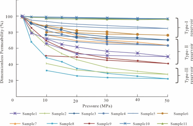
Based on the operating experience of the Xiangguosi Carboniferous gas storage in the adjacent area40,41, the operating pressure range is assumed to be 10–30 MPa. To simulate the actual pressure on the reservoir during the operation of the gas storage42, 11 core samples (Table 5) were selected for laboratory pressure sensitivity tests using an overburden pressure porosity and permeability tester (NER). Dimensionless permeability25 was calculated (Formula 5). Calculation results showed that when the effective pressure increased from 2 MPa to 50 MPa, the average dimensionless permeability of all samples was 63.3%, with an amplitude of decline of 36.7%. Type-I reservoirs were the least affected, with an amplitude of decline of 11.2%. Type-II reservoirs declined by 41.9%. Type-III reservoirs dropped abruptly by 74.6%.
 |
5 |
Table 5.
Basic data on physical properties in pressure sensitivity tests on reservoir rocks.
| Sample No. | Top depth (m) |
Length (cm) |
Diameter (cm) | Porosity (%) | Permeability (mD) | Reservoir type | Micro-pore structure |
|---|---|---|---|---|---|---|---|
| 1 | 3188.46 | 3.366 | 2.579 | 10.3 | 61.3 | II | Porous-fractured |
| 2 | 3427.00 | 4.120 | 2.582 | 3.2 | 0.489 | III | Porous |
| 3 | 3427.19 | 4.340 | 2.581 | 6.6 | 20.5 | II | Porous |
| 4 | 3437.51 | 5.083 | 2.582 | 8.1 | 26.7 | II | Porous-fractured |
| 5 | 3261.16 | 4.929 | 2.582 | 13.3 | 171 | I | Porous-fractured |
| 6 | 3266.18 | 4.875 | 2.583 | 14.2 | 27 | I | Porous-fractured |
| 7 | 3268.01 | 4.710 | 2.583 | 11.0 | 3.25 | II | Porous-fractured |
| 8 | 3254.94 | 3.451 | 2.583 | 4.0 | 10.3 | III | Porous |
| 9 | 3255.71 | 4.855 | 2.583 | 9.2 | 20.4 | II | Porous |
| 10 | 3270.01 | 5.138 | 2.582 | 14.5 | 2.3 | I | Porous |
| 11 | 3270.21 | 5.188 | 2.582 | 14.0 | 23.8 | I | Porous |
Note: V is dimensionless permeability; is the permeability after application of alternating stress; is original permeability. Quoted from reference [25].
Given the “aeration–deflation” characteristics of a gas storage site, permeability under the pressure of 10 MPa was taken as the baseline, and the recovery rate of permeability was analyzed by first boosting the pressure on the sample to 50 MPa and then relieving it to 10 MPa. Analysis results indicated that the recovery rate of permeability was 98.9% at the highest, 64.1% at the lowest, and 86.2% on average. Samples from different types of reservoirs had different recovery rates of permeability. Specifically, the average recovery rate of permeability of Type-I reservoirs was 96%, and that of Type-II and Type-III reservoirs, which account for a majority of reservoirs, also reached as high as 80.5%.
The permeability change of reservoir rocks is also affected by the pore structures. The permeability of porous reservoir rocks is slightly affected by pressure change, while that of porous-fractured reservoir rocks is greatly affected. This study analyzed the test data on four samples (Samples 5, 6, 10, and 11) from Type-I reservoirs. Analysis results show that Samples 5 and 6 have porous-fractured pore structures, while Samples 10 and 11 have ordinary pore structures. The four samples are similar in porosity but very different in permeability. The permeability of Samples 5 and 6 was far higher than that of Samples 10 and 11 (Table 5). In pressure sensitivity tests, the permeability change rates of Samples 5 and 6 under the pressure of 10–50 MPa were significantly higher than those of Samples 10 and 11 (Fig. 10).
Fig. 10.
Permeability-stress sensitivity curves of reservoir cores.
Conclusions
In the feasibility analysis of converting depleted gas reservoirs into gas storage facilities, the evaluation of reservoir sealing plays a significant role. This study utilized early-stage exploration and development data of the W gas reservoir and comprehensively accounted for the high-rate injection and production characteristics of the gas storage. A multi-factor comprehensive evaluation of the sealing capacity of the W gas reservoir was conducted. Therefore, a geological evaluation method is proposed for assessing the feasibility of converting depleted carbonate gas reservoirs controlled by faults into gas storage facilities. This method can serve as a reference for similar feasibility analyses in other depleted gas reservoirs. This study primarily examines the trap characteristics, cap rock integrity, fault sealing capacity, and reservoir stress sensitivity of the W gas reservoir. The conclusions are as follows:
(1) The W gas reservoir caprock is a superimposed composite caprock system composed of the direct caprock of the Liangshan Formation and the overlying ultra-thick and compact limestone formation. These formations are extensive and have good seal capacity for the underlying reservoir.
(2) Six major faults within the study area were selected for sealing evaluation. The qualitative analysis results indicate that the occurrence, properties, combination characteristics, and configuration relationships of the upper and lower walls of the faults all demonstrate good sealing potential. Quantitative analysis further confirms this, with fault sealing coefficients ranging from 19 to 30, all exceeding the threshold of 15, which signifies good sealing performance. Additionally, the SGR values range from 72.05 to 76.59%, surpassing the 70% threshold, indicating robust sealing properties and meeting the requirements for gas storage facility renovation.
(3) The reservoir section of the W gas reservoir is a porous-fractured reservoir mainly composed of particle dolomite, powder crystal-fine-crystalline dolomite, and breccia dolomite. Vertically, Sub-member C2hl21 has the best physical properties. Horizontally, Wellblock C30-C10-C18 has the best reservoir development. According to the analysis of alternating stress tests, the overall recovery of permeability after a pressure drop is desirable. The permeability of porous reservoir rocks is slightly affected by pressure change, while that of porous-fractured reservoir rocks is greatly affected.
Acknowledgements
This research was financially supported by the “Thirteenth Five-Year Plan” National Major Project “Key Marine Strata Sedimentary Facies Research” (No. 2016ZX05007002).
This research was financially supported by the “Thirteenth Five-Year Plan” National Major Project “Key Marine Strata Sedimentary Facies Research” (No. 2016ZX05007002).
Author contributions
Z. Hu as the corresponding author, led the research effort, which received oversight from N. Zhang, D. Zhou, G. Zhou, X. Chen; Z. Tong was responsible for composing and editing the manuscript; L. Qiu provided guidance for the manuscript writing work; Reservoir stress sensitivity data from Y. Zhu; Y. Shao analyzed seismic data and J. Hu analyzed the thin sections.
Data availability
The datasets generated during and/or analysed during the current study are available from the corresponding author on reasonable request.
Declarations
Competing interests
The authors declare no competing interests.
Footnotes
Publisher’s note
Springer Nature remains neutral with regard to jurisdictional claims in published maps and institutional affiliations.
Contributor Information
Zhonggui Hu, Email: hzg1978@yangtzeu.edu.cn.
Longwei Qiu, Email: qiulwsd@163.com.
References
- 1.Ma, X. H. et al. Development directions of major scientific theories and technologies for underground gas storage[J]. Nat. Gas. Ind.42 (5), 93–99. 10.3787/j.issn.1000-0976.2022.05.010 (2022). [Google Scholar]
- 2.Wei, G. Q. et al. Geological theory and application of underground gas storage in China. Acta Petrolei Sin. 40 (12), 1519–1530. 10.7623/syxb201912011 (2019). [Google Scholar]
- 3.Zheng, Y. L. et al. Connotation and evaluation technique of geological integrity of UGSs in oil-gas fields. Nat. Gas. Ind.40 (5), 94–103. 10.3787/j.issn.1000-0976.2020.05.012 (2020). [Google Scholar]
- 4.Ma, X. H. et al. Key technologies and practice for gas field storage facility construction of complex geological conditions in China. Pet. Explor. Dev.45 (3), 489–499. 10.11698/PED.2018.03.14 (2018). [Google Scholar]
- 5.Zheng, D. W. et al. Key evaluation techniques in the process of gas reservoir being converted into underground gas storage. Pet. Explor. Dev.44 (5), 794–801. 10.11698/PED.2017.05.15 (2017). [Google Scholar]
- 6.Sun, J. C. et al. Injection–production mechanisms and key evaluation technologies for underground gas storages rebuilt from gas reservoirs[J]. Nat. Gas. Ind.38 (4), 138–144. 10.3787/j.issn.1000-0976.2018.04.016 (2018). [Google Scholar]
- 7.Zhou, Y. et al. Current status and progress in research of hydrocarbon cap rocks. Petrol. Geol. Exp.. 34 (3), 234–245. 10.11781/sysydz201203234 (2012). [Google Scholar]
- 8.Zhang, L. H. & Zhou, G. S. Improvement and application of the methods of gas reservoir cap sealing ability. Acta Sedimentol. Sin. 28(2), 388–394 (2010). 10.14027/j.cnki.cjxb.2010.02.021
- 9.Song, J. Y. Nanpu Sag the Second Member of Dongyingzu Fm Mudstone Caprock Sealing Capacity Comprehensive Evaluation (Northeast Petroleum University, 2016).
- 10.Jia, S. P. et al. Quantitative assessment of the gas-sealing capacity of the Permian claystone caprock for the D5 aquifer gas storage in the Litan sag. Hydrogeol. Eng. Geol.43 (3), 79–86. 10.16030/j.cnki.issn.1000-3665.2016.03.13 (2016). [Google Scholar]
- 11.Lin, J. P. et al. Comprehensive evaluation of sealing ability of mudstone cap rock for xing 9 depleted gas reservoir in reconstructing underground gas storage. Chin. J. Rock Mech. Eng. 34(S2), 4099–4107 (2015). 10.13722/j.cnki.jrme.2014.1595
- 12.Liu, L. et al. Comprehensive evaluation of sealing capacity of depleted gas reservoir reconstructed to gas storage: a case study of Xu2 gas reservoir in Zhongba Gas Field, Northwest Sichuan. Petrol. Geol. Oilfield Dev. Daqing 1-9. 10.19597/j.issn.1000-3754.202109053
- 13.Wang, B. et al. Logging evaluation of key issues of Xinjiang H underground gas storage conversion. J. Southwest Petrol. Univ. (Sci. Technol. Ed.)38(1), 46–52 (2016). https://link.cnki.net/urlid/51.1718.TE.20160104.1711.024
- 14.Shen, Q. et al. Quantitative evaluation for sealing effectiveness of cap rocks in Nanpu Sag. Fault-Block Oil Gas Field22(4), 415–418 (2015). https://link.cnki.net/urlid/41.1219.te.20150721.0817.002
- 15.Shu, P. et al. Cap rock sealing-property classifying standard and evaluation of Shengping gas storage in Daqing Oil filed. Petrol. Geol. Oilfield Dev. Daqing38(5), 272–276 (2019). 10.19597/j.issn.1000-3754.201906025
- 16.Chen, K. et al. The validity quantitative evaluation technology and its application to structural trap in Weizhou Formation, Weixinan Sag. Acta Petrol. Sin.39(12), 1370–1378 (2018). 10.7623/syxb201812005
- 17.Wang, K. & Dai, J. S. A quantitative relationship between the crustal stress and fault sealing ability. Acta Petrol. Sin. 33 (1), 74–81. 10.7623/syxb201201009 (2012). [Google Scholar]
- 18.Fu, G., Shi, J. J. & Lv, Y. F. An improvement in quantitatively studying lateral seal of faults. Acta Petrol. Sin. 33 (3), 414–418. 10.7623/syxb201203010 (2012). [Google Scholar]
- 19.Shi, J. J. et al. Dynamic damage of fault to caprock and its influence on hydrocarbon transport: A case study of Gangdong fault in Qikou sag, Bohai Bay Basin. Acta Petrol. Sin. 40(8), 956–964 (2019). 10.7623/syxb201908006
- 20.Ma, X. M. et al. Study on fault sealing for Bannan underground gas storage. Mud Logging Eng. 22(4), 77–79, 84 (2011). 10.3969/j.issn.1672-9803.2011.04.021
- 21.Zhang, X. S. et al. A comment on research methods of fault sealing capacity. Lithol. Reserv. 25 (2), 123–128. 10.3969/j.issn.1673-8926.2013.02.022 (2013). [Google Scholar]
- 22.Lv, Y. F. et al. Quantitative evaluation method of fault lateral sealing. Petrol. Explor. Dev.43(2), 310–316 (2016). https://link.cnki.net/urlid/11.2360.te.20160126.0943.004
- 23.Zhang, Y. Application of shale gouge ratio method in quantitative evaluation of lateral fault sealing of gas storage: A case study of Zhongyuan Wen23 gas storage. Mud Logging Eng.30(3), 39–44, 51 (2019). https://link.cnki.net/urlid/12.1371.TE.20190812.0856.002
- 24.Zhou, D. Y. et al. Laboratory researches on stress sensibility of underground gas storage . Nat. Gas Indus.4, 122–124, 165 (2006). 10.3321/j.issn:1000-0976.2006.04.040
- 25.Zhu, H. Y. et al. Permeability changes of fracture-pore type reservoir under the conditions of alternating pressure: Case study of Shapingchang carbonate gas reservoir in eastern Sichuan Basin. Nat. Gas Geosci. 32(6), 914–922 (2021). 10.11764/j.issn.1672-1926.2021.03.006
- 26.Ding, Y. H. et al. Seepage laws in converting a microfissure-pore carbonate gas reservoir into a UGS. Nat. Gas Indus. 35(1), 109–114 (2015). 10.3787/j.issn.1000-0976.2015.01.015
- 27.Li, Z., Lei, X. & Yan, L. The division of sequence stratigraphy and analysis of reservoir characteristics in Huanglong Formation of carboniferous in east Sichuan area. Geophys. Prospect. Petrol.. 1, 39–43. 10.3969/j.issn.1000-1441.2005.01.011 (2005). [Google Scholar]
- 28.Zheng, R. C., Peng, J. & Gao, H. C. Palaeokarst-related characteristics and cycles of carbonate reservoirs in Huanglong Formation, Upper Carboniferous, Eastern Chongqing. Geol.-Geochem. 1, 28–35. https://kns.cnki.net/kcms2/article (2003).
- 29.Hu, Z. G., Zheng, R. C. & Wen, H. G. Sequence-lithofacies paleogeographic study on Huanglong Formation in Eastern Chongqing Western Hubei area. Acta Sedimentolx. Sin.28(4), 696–705, 2010 (2003). 10.14027/j.cnki.cjxb.2010.04.014
- 30.Li, W., Zhang, Z. J. & Dang, L. R. Depositional systems and evolution of the Upper Carboniferous Huanglong Formation in the eastern Sichuan Basin. Pet. Explor. Dev.38 (4), 400–408 (2011). https://kns.cnki.net/kcms2/article/abstract [Google Scholar]
- 31.Zhao, J. L. & Gao, X. L. Evaluation technique of mudstone caprock based on logging data. Well Logging Technol.37(6), 594–599 (2013). 10.3969/j.issn.1004-1338.2013.06.002
- 32.Jiao, C. H. & Gu, Y. F. Application of log data in evaluating caprocks. Well Logging Technol.90(1), 45–47 (2004). 10.3969/j.issn.1004-1338.2004.01.012
- 33.Fu, G., Fu, X. F. & Meng, Q. F. Research of capillary seal ability and its formation period of mudstone caprock with acoustic transit time. Geophys. Prospect. Petrol. 2, 261–264. 10.3969/j.issn.1000-1441.2003.02.024 (2003).
- 34.Shao, Y. L. et al. Fault sealing evaluation of carbonate gas storage in high-steep structural belt: Taking WSC gas field in eastern Sichuan as an example. J. Yangtze Univ. (Nat. Sci. Ed.)19(1), 1–8 (2022). 10.16772/j.cnki.1673-1409.20220211.005
- 35.Qie, Y. et al. Fault zone structure and hydrocarbon accumulation in carbonates. J. Jilin Univ. Earth Sci. Ed. 44(3), 749–761 (2014). 10.13278/j.cnki.jjuese.201403104
- 36.LIU, C. H. L. I. Y. R. et al. Comparison analysis and application of the shale smear quantitative calculation. J. Oil Gas Tecnol.31(1), 164–166 + 396 (2009). https://kns.cnki.net/kcms2/article/
- 37.Xiao, Y. X., Gong, X. L. & He, X. Y. Analysis of fault sealing and estimate of height of hydrocarbon column in fault trap by SGR method: A case of application in G fault block in eastern China. Marine Origin Petrol. Geol. 4, 51–58 (2005). https://kns.cnki.net/kcms2/article/abstract?
- 38.Sun, J. C. et al. Injection–production mechanisms and key evaluation technologies for underground gas storages rebuilt from gas reservoirs. Nat. Gas Indus. 38(4), 138–144 (2018). 10.3787/j.issn.1000-0976.2018.04.016
- 39.Xu, H. C., Wang, J. M. & Qu, P. A prediction model of storage capacity parameters of a geologically-complicated reservoir-type underground gas storage (UGS). Nat Gas Indus. 35(1), 103–108 (2015). 10.3787/j.issn.1000-0976.2015.01.014
- 40.Wu, J. F. et al. Operation parameter design of the Xiangguosi underground gas storage based on the Carboniferous gas reservoir. Nat. Gas Indus.32(2), 91–94, 121–122 (2012). 10.3787/j.issn.1000-0976.2012.02.022
- 41.Zhao, Y. C. et al. In-situ stress simulation and integrity evaluation of underground gas storage: A case study of the Xiangguosi underground gas storage, Sichuan, SW China.J. Geomech.28(4), 523–536 (2022). 10.12090/j.issn.1006-6616.2021138
- 42.Qi, G. X. Experimental study on reservoir stress sensitivity of underground storage of depleted gas reservoirs. Petrol. Geol. Eng.34(3), 76–80 (2020). 10.3969/j.issn.1673-8217.2020.03.015
Associated Data
This section collects any data citations, data availability statements, or supplementary materials included in this article.
Data Availability Statement
The datasets generated during and/or analysed during the current study are available from the corresponding author on reasonable request.


