Abstract
Based on the elastic–plastic theory, the analytical formula of the second invariant J2 of deviatoric stress at any point around the circular roadway under the non-uniform stress field is derived. The distribution law of J2 of surrounding rock under the three-dimensional non-isobaric stress field is studied by theoretical analysis and numerical simulation. Combined with the butterfly failure theory of surrounding rock of roadway, the close relationship between the distribution pattern of J2 and the distribution pattern of plastic zone is found, and the failure mechanism of surrounding rock is revealed. The results show that the distribution form of the second invariant J2 of deviatoric stress is closely related to the distribution form of plastic zone. When the distribution of J2 of surrounding rock shows ‘round’, ‘oval’ and ‘butterfly’, the plastic zone shows the corresponding consistent form. When the second invariant J2 of deviatoric stress produces stress concentration, the surrounding rock of roadway will produce large-scale damage. When the stress concentration is high, it may lead to malignant expansion of surrounding rock of roadway. The distribution of the second invariant J2 of deviatoric stress is directional. When the principal stress rotates over a certain angle, the second invariant J2 of deviatoric stress rotates over the same angle as the plastic zone. Under the influence of superimposed mining, the second invariant deviatoric stress J2 of the wind tunnel of Yangchangwan 160,206 working face presents butterfly distribution, and the stress butterfly leaves present a certain degree of rotation. Based on the failure mode of plastic zone, the corresponding optimization support scheme is proposed, and the engineering effect is good.
Keywords: Surrounding rock control, Butterfly plastic zone, Deviatoric stress field, Second invariant of deviatoric stress, Roadway
Subject terms: Engineering, Civil engineering
Introduction
Energy is a major event related to the overall situation of economic and social development, and coal has long been the ballast and stabilizer of China’s energy security. With the increase of deep mining in coal mines and the increasing complexity of mining conditions, a series of safety problems such as roadway instability are becoming more and more prominent. The stability control of deep roadway surrounding rock has become one of the research hotspots at home and abroad1,2. In the problem of plastic mechanics, the development of plastic deformation of roadway surrounding rock is mainly controlled by deviatoric stress3, and deviatoric stress is of great significance to the study of deformation and failure of roadway surrounding rock.
In the problem of plastic mechanics, the development of plastic deformation of roadway surrounding rock is mainly controlled by deviatoric stress4, and deviatoric stress is of great significance to the study of deformation and failure of roadway surrounding rock. Many scholars have analyzed the stability of roadway surrounding rock based on deviatoric stress, and have achieved a series of research results5–8. Zhao et al.9 studied the distribution law of deviatoric stress and strain energy density of roadway surrounding rock under three-dimensional non-isobaric stress field, deduced the mechanical solution of the maximum principal deviatoric stress S1 and the minimum principal deviatoric stress S3 of circular roadway surrounding rock, and analyzed the distribution law of the maximum principal deviatoric stress and strain energy density of roadway surrounding rock in different dominant stress fields. He et al.10 analyzed the stability of roadway surrounding rock with the maximum principal deviatoric stress as the index, and obtained the distribution of deviatoric stress under different stress states. Based on this, a high-strength comprehensive control technology was proposed, and the industrial test results were good. Wang et al.11 took the second invariant of deviatoric stress as the index, combined with the numerical simulation FLAC3D to analyze the stability control of surrounding rock of coal roadway under the influence of multiple mining, and revealed the deformation and failure mechanism of coal rock under the influence of severe mining. In the aspect of deviatoric stress distribution and plastic zone evolution law of roadway surrounding rock, Ma et al.12 studied the deviatoric stress field and plastic zone distribution law of roadway surrounding rock based on the circular hole stress solution in elastic mechanics and the deviatoric stress theory in plastic mechanics, combined with Mohr–Coulomb criterion, and deduced the calculation expression of deviatoric stress of roadway surrounding rock under non-uniform stress field and the analytical solution of plastic zone radius r. Yu et al.13 established the constitutive equation of deviatoric stress and plastic zone distribution through the theory of rock mechanics, and proposed that the surrounding rock of roadway will form typical positive symmetric instability mode and typical angular symmetric instability mode. Based on the plane strain problem, Shi et al.14 found that J2 will show a butterfly distribution, and clarified that the second invariant of deviatoric stress has an important influence on the failure distribution of plastic zone.
In this paper, the mining roadway of Yangchangwan Mine is taken as the engineering background, and the deviatoric stress environment and failure characteristics of the surrounding rock of the mining roadway are taken as the starting point. By introducing the second invariant J2 of the deviatoric stress tensor which can characterize the shear stress failure strength, the relationship between the distribution form and direction of the J2 stress field and the plastic zone of the surrounding rock of the roadway under the deviatoric stress field is established, and the mechanical mechanism of the formation of different forms of the plastic zone of the surrounding rock of the roadway in the deviatoric stress field is revealed. On this basis, the temporal and spatial evolution law of the stress and plastic zone of the mining roadway in Yangchangwan Mine during the whole process of excavation and mining is studied, and the non-uniform failure mechanism of the surrounding rock of the mining roadway under the deviatoric stress field is revealed. The stability control principle of surrounding rock of mining roadway under deviatoric stress field is put forward, and the control technology of surrounding rock of mining roadway under deviatoric stress field is formed, and the field industrial test is carried out, so as to enrich the theory of plastic zone of surrounding rock of roadway and the practice of stability control.
Analytical solution of the second invariant J2 of deviatoric stress
Elastic–plastic analysis of surrounding rock under non-uniform stress field
In underground engineering, the surrounding rock of roadway is in the three-dimensional stress field. Due to the complexity of its mathematical and mechanical analysis, the previous scholars usually use the plane strain problem to discuss. However, the model ignores the axial force of the roadway and cannot truly describe the three-dimensional stress environment of the roadway. Some theoretical studies have shown that the axial force of the roadway has an effect on the range of the plastic zone of the surrounding rock of the roadway, and the influence of the axial stress is different with the change of the stress state. Therefore, the three-dimensional stress environment of the roadway should be fully considered. When dealing with roadways with complex stress conditions such as inclined roadways and cross-layer roadways, it should be regarded as a three-dimensional space problem in elastic mechanics1,15.
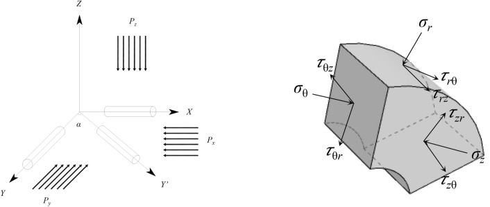
The analysis diagram of roadway surrounding rock affected by three-dimensional stress is shown in Fig. 1. In the Figure Px, Py and Pz represent the three-dimensional stress of X, Y and Z axes. Under the condition of three-dimensional stress, according to the theory of elastic mechanics15, the stress solution of any point around the surrounding rock of circular roadway in polar coordinate system can be obtained as follows:
 |
1 |
where σr is the radial stress at any point, σθ is the circumferential stress at any point, σy is the axial stress of the roadway, τrθ is the shear stress at any point, a is the radius of the surrounding rock of the roadway, r and θ are the polar coordinates of any point around the roadway, ν is the Poisson’s ratio of the surrounding rock of the roadway.
Fig. 1.
Mechanical model diagram under three-dimensional stress field.
The principal stress expression of any point of roadway surrounding rock can be obtained by elastic mechanics:
 |
2 |
where σ1 is the maximum principal stress at any point, σ2 is the intermediate principal stress at any point, and σ3 is the minimum principal stress at any point.
Analytical solution of the second invariant J2 of deviatoric stress of surrounding rock
Under general conditions, the volume and shape of the surrounding rock of the roadway will change under the action of external force. In the classical plastic theory and elastic theory, the stress sphere tensor only produces volumetric strain and has no shape change. The deviatoric stress tensor will produce shear deformation, which reflects the degree to which the actual stress state of an object deviates from the uniform stress state. Therefore, the plastic deformation of rock mass is closely related to the deviatoric stress tensor3,16.
Here, the spherical tensor component of the stress tensor is denoted as:
 |
3 |
 |
4 |
The left side of Eq. (4) is the stress tensor σ, the first term on the right side is the stress sphere tensor, and the second term is the stress partial tensor.
According to the theory of elastoplastic mechanics, the size of the deviatoric stress tensor will change with the change of the coordinate system. The randomness of the coordinate system leads to the randomness of the tensor component, and the deviatoric stress tensor invariant will not change due to the change of the coordinate system17. The second invariant J2 of deviatoric stress has rich physical meaning, and its expression is as follows:
 |
5 |
It can be seen from Eq. (5) that J2 is the comprehensive quantitative index of σ1, σ2, σ3, and the relationship between J2 and each shear stress is shown in Eq. (6):
 |
6 |
The above formula shows that J2 has a fixed relationship with the generalized shear stress q, octahedral shear stress  and pure shear stress
  . In the plastic theory, the main reason for the yield failure of the material is caused by the shear stress of the material. Therefore, the second invariant J2 of deviatoric stress can reflect the failure of rock mass and can better reflect the essence of rock mass deformation and failure.
At this time, the Eq. (1) is brought into the Eq. (2) the principal stress transformation formula σ1, σ2, σ3 is brought into the Eq. (5), and the analytical expression of the second invariant J2 of the deviatoric stress at any point around the roadway can be obtained as the Eq. (7):
 |
7 |
Among them,  , here let:
 |
Here, according to the simplification, the second invariant J2 of the deviatoric stress at any point of the roadway surrounding rock can be resolved into an eight-order implicit equation related to the radius, such as Eq. (8):
 |
8 |
Under the condition that Px, Py, Pz and Poisson’s ratio v are given, the second invariant J2 of deviatoric stress at any point of roadway surrounding rock can be calculated by taking r and θ into account.
Study on the relationship between J2 and plastic zone morphology
Study on J2 distribution law of roadway surrounding rock
In order to further explore the relationship between the second invariant J2 of deviatoric stress and the plastic zone shape of roadway surrounding rock, the Px, Py and Pz of different ratios are brought into Eq. (8), and the second invariant distribution map of deviatoric stress under different stress field conditions is drawn by using the built-in command of Maple software.
At present, the existing research proposes that the plastic zone of roadway surrounding rock has three forms: circular, elliptical and butterfly. The circular form only exists when Px:Py = 1. With the increase of Px:Py ratio, the plastic zone of surrounding rock changes from circular to elliptical and then to butterfly. Here we fix the size of Pz is 15 MPa, Px:Py = 1, Poisson’s ratio v = 0.25, the radius of the roadway is 3 m. Three groups of loading schemes are set according to different lateral pressure coefficients, and the stress loading scheme is shown in Table 1.
Table 1.
Loading scheme of partial stress in surrounding rock of roadway.
| Numbering | Px/MPa | Py/MPa | Pz/MPa |
|---|---|---|---|
| I | 6 | 6 | 15 |
| II | 12 | 12 | 15 |
| III | 15 | 15 | 15 |
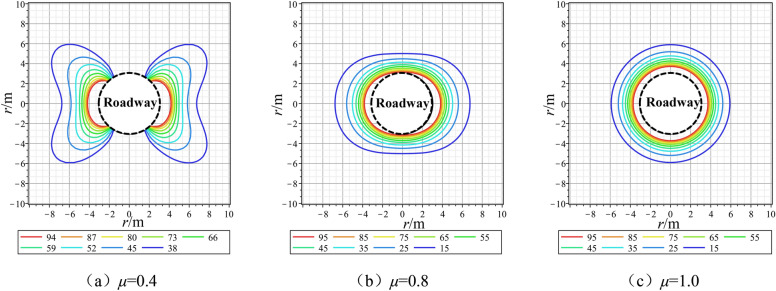
The distribution of the second invariant J2 isoline of the deviatoric stress of roadway surrounding rock under different stress loading conditions is shown in Fig. 2. From the isoline stress diagram, it can be seen that.
Fig. 2.
Isoline distribution map of the second invariant J2 of roadway surrounding rock under different lateral pressure coefficients.
The distribution of the second invariant J2 isoline of the deviatoric stress of roadway surrounding rock under different stress loading conditions is shown in Fig. 2. When μ = 1.0, the size of J2 around the roadway surrounding rock is exactly the same, and the size of J2 around the roadway is decreasing in a ‘ring’ shape. When μ = 0.8, the distribution around the roadway J2 began to show non-uniform characteristics, the J2 at the roof of the roadway gradually decreased, the deviatoric stress of the two sides of the roadway gradually increased, and the deviatoric stress contour showed a transverse elliptical distribution. When μ = 0.4, the deviatoric stress at the roof of the roadway continues to decrease, and the deviatoric stress at the side of the roadway gradually increases. As the distance from the roadway increases, the deviatoric stress of the roadway gradually expands to the angular bisector of the four quadrants, and the shape of the deviatoric stress of the surrounding rock of the roadway presents a butterfly shape.
From the above comprehensive analysis, it can be seen that the J2 distribution patterns of roadway surrounding rock under different stress environments are roughly divided into three types: ‘round’, ‘oval’ and ‘butterfly’. Under different stress conditions, the concentration degree of J2 at different positions around the roadway is quite different. When the surrounding rock of the roadway is in the state of hydrostatic pressure, the stress concentration degree of the roadway is completely consistent. When the partial stress form of the roadway is elliptical, the support of the two sides or the roof and floor should be paid attention to. When the partial stress of the roadway is butterfly shape, the stress concentration of the four quadrant angle bisector of the roadway should be paid attention to.
Theoretical study on the relationship between J2 distribution and plastic zone morphology
After roadway excavation, energy release occurs around the roadway, and deviatoric stress concentration occurs around the roadway. Deviatoric stress J2 leads to plastic deformation of rock mass, which may lead to malignant expansion of plastic zone in severe cases. Therefore, it is of great significance for reasonable roadway support design to deeply study the relationship between J2 distribution law and plastic zone morphology of roadway.
In Refs.18,19, the eighth-order implicit equation of plastic zone boundary at any point of surrounding rock of circular roadway in non-uniform stress field is derived. The approximate implicit solution is based on the most commonly used Mohr–Coulomb criterion as the failure criterion, and the stress solution of any point of surrounding rock of circular roadway in elastic mechanics theory is brought into the criterion.
According to the eight-order implicit equation of the plastic zone, some specific parameter values are set, a = 3 m, φ = 27°, C = 2 MPa. By bringing the above three stress loading schemes into the equation, the plastic zone morphology under different stress loading conditions is obtained as shown in Fig. 3.
Fig. 3.
Morphology distribution of plastic zone under different stress loading schemes of roadway surrounding rock.
Reference20 gives the criteria for judging the shape of the plastic zone of the surrounding rock of the roadway. Through the shape distribution of the plastic zone in Fig. 3 and the criteria for judging the shape, the following rules can be obtained:
When the lateral pressure coefficient is 0.4, the longitudinal axis and transverse axis of the coordinate shrink in the direction of the center of the coordinate circle, and the boundary of the plastic zone in the coordinate quadrant expands. The maximum boundary of the plastic zone of the roadway occurs in four quadrants, and the shape of the plastic zone is ‘vertical butterfly’.
When the lateral pressure coefficient is 0.8, the minimum boundary is located on the longitudinal axis of the coordinate axis, the elliptical focus is located on the transverse axis, and the shape of the plastic zone is ‘transverse ellipse’.
When the lateral pressure coefficient is 1.0, in the hydrostatic pressure field, the plastic zone boundary of the roadway surrounding rock is a standard ‘circular’ shape.
Through the study of J2 distribution law under different stress fields of roadway surrounding rock in “Study on J2 distribution law of roadway surrounding rock” section and the study of plastic zone morphology under different stress fields in “Theoretical study on the relationship between J2 distribution and plastic zone morphology” section, it can be seen that under different stress fields, the distribution pattern of J2 is almost the same as that of plastic zone, showing three forms of ‘circle’, ‘oval’ and ‘butterfly’. In summary, it can be found that the distribution pattern of J2 is closely related to the shape of plastic zone.
Numerical simulation study on the relationship between J2 distribution and plastic zone morphology
FLAC3D can simulate the stress characteristics and plastic flow analysis of three-dimensional structures such as soil and rock. Therefore, in this paper, the finite difference method is used to simulate the distribution characteristics of the second invariant J2 of deviatoric stress and the failure range and morphology of plastic zone under different three-dimensional stress fields, so as to analyze the close relationship between deviatoric stress morphology and plastic zone morphology.
In this paper, a numerical model with a circular roadway section is established. This model has a total of 153,360 units. The surrounding rock is regarded as the equivalent rock mass material of the same sex. The rock mechanics parameters are shown in Table 2. The Mohr–Coulomb model is used. The surrounding and bottom of the model are set as the displacement boundary, the roof is set as the stress boundary, and the upper load is 15 MPa.
Table 2.
Molar coulomb rock mechanics parameter table.
| Poisson ratio | Cohesion/MPa | Tensile strength/MPa | Bulk modulus/GPa | Angle of internal friction/(°) |
|---|---|---|---|---|
| 0.25 | 2 | 1.5 | 4 | 27 |
In this simulation, three simulation schemes under different stress environments are set up, and different load loading parameters are shown in Table 2 in “Study on J2 distribution law of roadway surrounding rock” section.
Figure 4 shows the J2 distribution diagram under different lateral pressure coefficients. It can be seen from the Fig. that: (1) Due to the excavation of the roadway, the second invariant deviatoric stress is redistributed, the deviatoric stress unloading occurs around the excavation space, and the J2 concentration area develops to the deep part of the roadway. (2) When the lateral pressure coefficient is 0.4, the distribution of J2 presents a butterfly shape, and the deviatoric stress J2 is mainly concentrated in the side and four corners of the roadway, and the deviatoric stress at the side and wing angle increases first and then decreases with the increase of surrounding rock depth. (3) When the lateral pressure coefficient is 0.8, the distribution of J2 presents an elliptical shape, and the concentration of J2 in the two sides is greater than that in the roof and floor. (4) When the lateral pressure coefficient is 1, the distribution of J2 presents a circular shape, and the concentration of J2 around the roadway is very uniform.
Fig. 4.
Diagram of J2 distribution under different lateral pressure coefficients.
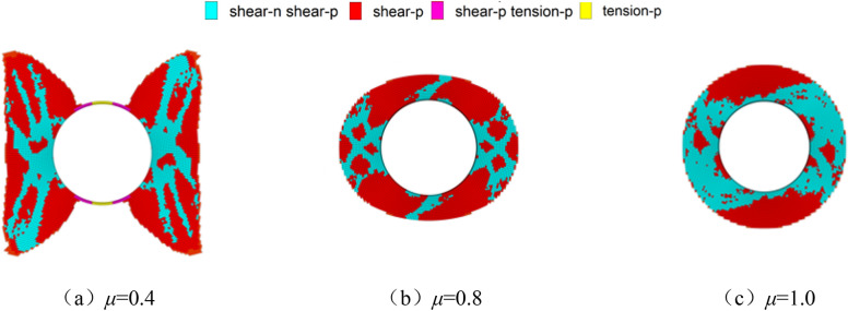
The distribution diagram of plastic zone under different lateral pressure coefficients is shown in Fig. 5. When the lateral pressure coefficient is 0.4, the plastic zone of surrounding rock is characterized by butterfly shape. When the lateral pressure coefficient is 0.8, the plastic zone of surrounding rock is characterized by elliptical shape. When the lateral pressure coefficient is 1.0, the plastic zone of surrounding rock is characterized by circular shape.
Fig. 5.
Diagram of plastic zone distribution under different lateral pressure coefficients.
Through the numerical simulation results of Figs. 4 and 5, it can be seen that the distribution of the second invariant deviator stress J2 of the surrounding rock of the roadway is closely related to the distribution of the plastic failure of the surrounding rock. When the distribution of J2 presents butterfly, oval and circular, the plastic zone failure also presents the corresponding form.
Study on J2 directionality of surrounding rock under non-uniform stress field
In the process of advancing the working face, the direct roof is constantly falling due to the increase of the exposed area, and the hinged structure formed by the rock block during the rotation process leads to the rotation of the local stress field direction of the surrounding rock of the roadway. When the stress field of the roadway rotates, it will lead to the rotation of the plastic zone of the surrounding rock of the roadway. When the shape of the plastic zone is’butterfly’, the rotation of the stress field will cause the butterfly leaf to be located near the roof, which may lead to serious roof fall disaster.
Theoretical analysis of J2 directionality of surrounding rock under non-uniform stress field
In order to study the directionality of the second invariant deviator stress J2, the deflection angle α is brought into Eq. (7) to obtain the expression of the second invariant deviator stress when the stress rotates (Eq. 9):
 |
9 |
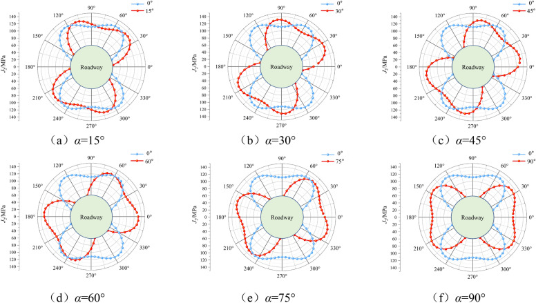
In order to study the influence of principal stress deflection on J2 distribution, the deflection angles α of 0°, 15°, 30°, 45°, 60°, 75° and 90° are brought into Eq. (9). The J2 distribution diagram when Px = 20 MPa, Py = 10 MPa, Pz = 8 MPa, v = 0.25, a = 3 m and 5 m away from the center of the roadway is shown in Fig. 6:
Fig. 6.
J2 distribution diagram under different stress deflection angles.
It can be clearly seen from Fig. 6 that under the above stress environment, the J2 distribution at the radius of 5 m of the roadway presents a butterfly shape, and the J2 distribution will deflect to a certain extent with the rotation of the principal stress. When the principal stress of the roadway deflects at a certain angle, the roadway J2 also deflects through the same angle, and the deflection of the principal stress leads to a significant difference in the distribution of J2 values around the roadway. And when α is 0°, the J2 distribution value of the roadway roof and the wing angle is much larger than that of the two sides. When α is 45°, the deviatoric stress value of the first three quadrants of the roadway coordinate system is larger. When α is 90°, the J2 distribution value of the two sides of the roadway and the wing angle is much larger than that of the roof and floor.
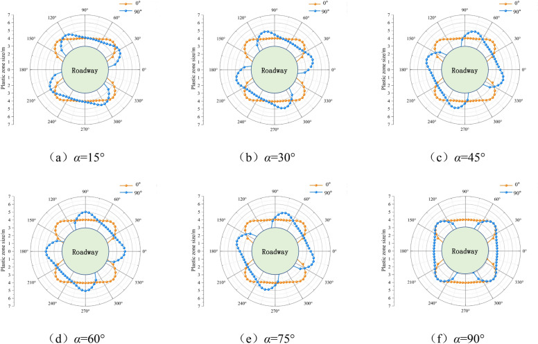
In the literature21, the boundary equation of plastic zone under the condition of principal stress deflection under non-hydrostatic pressure is derived. The above stress environment is brought into the equation to obtain the plastic zone distribution diagram of roadway surrounding rock under different deflection angles as shown in Fig. 7 (a = 3 m, φ = 29°, C = 3 MPa).
Fig. 7.
Diagram of plastic zone distribution under different stress deflection angles.
From Fig. 7, it can be seen that under the above stress environment, the shape of the plastic zone of the surrounding rock of the roadway presents a butterfly distribution, which is consistent with the distribution of the above deviatoric stress J2. The butterfly leaf in the plastic zone will deflect with the rotation of the principal stress. When the principal stress rotates at a certain angle, the plastic zone will also deflect at the same angle, and the shape of the plastic zone will not change. In addition, there is a one-to-one correspondence between the J2 value and the depth of the plastic zone. The larger the J2 value of the surrounding rock of the roadway, the greater the depth of the plastic zone. When α is 0°, the failure of surrounding rock mainly occurs in the roof and floor of the roadway and the four corners, and almost no damage occurs in the two sides. When α is 45°, the roof and floor, two sides and one and three quadrants of the roadway are damaged in a large range, while the damage range near the angle bisector of the two and four quadrants is smaller. When α is 90°, a large range of damage occurs at the two sides of the roadway and the wing angle, and the roof and floor are almost not damaged.
Numerical simulation study on J2 directionality of surrounding rock under non-uniform stress field
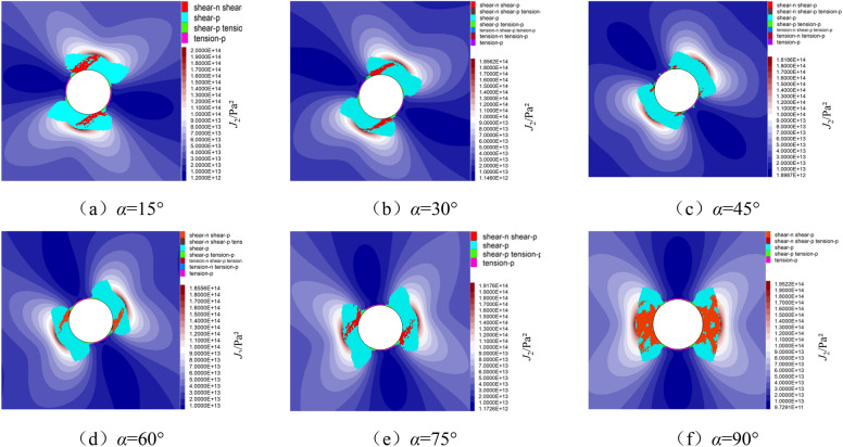
On the basis of theoretical analysis, the numerical simulation analysis of the above six different stress deflection angles is carried out. The plastic zone and J2 distribution obtained by numerical simulation analysis are shown in Fig. 8 (a = 3 m, φ = 29°, C = 3 MPa).
Fig. 8.
The diagram of plastic zone and J2 distribution under different stress deflection angles.
It can be seen from Fig. 8 that J2 presents a butterfly distribution under different stress deflection angles, and the stress butterfly leaf deflects with the rotation of the principal stress direction. The rotation angle is almost the same as the stress deflection angle, which is consistent with the above theoretical analysis results. For the distribution of plastic zone of surrounding rock, the shape of plastic zone under different stress deflection angles is butterfly, which is completely consistent with the distribution of J2, and the deflection angle of butterfly leaf in plastic zone is almost consistent with the deflection angle of principal stress, which is also consistent with the above theoretical analysis.
Combined with the schematic diagram of plastic zone and deviatoric stress distribution, it can be seen that when the J2 distribution is deflected, it may lead to J2 concentration near the roadway roof. When the concentration of deviatoric stress is high, it will lead to a wide range of uneven plastic expansion of the roof. In severe cases, it may lead to roof leakage and roof fall accidents.
Based on the above analysis, it can be seen that when the principal stress rotates at a certain angle, the second invariant J2 of the deviatoric stress of the surrounding rock and the plastic zone both deflect through the same angle. Combined with the analysis of “Theoretical study on the relationship between J2 distribution and plastic zone morphology” section, it can be seen that when the stress concentration occurs in J2, it will lead to a large range of damage to the surrounding rock. Therefore, when analyzing the stability of roadway surrounding rock, we should pay attention to the directionality of the second invariant J2 of roadway deviatoric stress, and focus on supporting the J2 concentration area.
Project applications
Engineering overview and deformation and failure of surrounding rock
The average vertical depth of 160,206 fully mechanized caving face in Yangchangwan Coal Mine is 592 m from the ground. The north is bounded by the 1#open-off cut of 160,206 working face, and the south is bounded by the return air downhill in the north wing of 16 mining area. The working face is adjacent to the goaf of 120,212 working face, and the coal pillar is set at 30 m. The 160,206 working face adopts the longwall retreating top coal caving mining method. The mining height is 4 m, the top coal thickness is 5.3 m, and the mining ratio is N = 1:1.33. The return air roadway of 160,206 working face is 2387 m, and the working face distribution diagram is shown in Fig. 9.
Fig. 9.
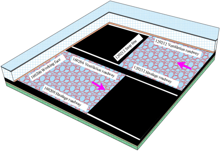
160,206 working face layout diagram.
The second-layer coal roof is a composite roof, and the lithology changes greatly. There is a thin layer of false roof in the local area, and the thickness changes greatly. The bottom of the direct roof often contains several layers of thin coal, which causes the roof to fall easily. There are some deformation and failure characteristics of surrounding rock in some areas of 160,206 return air roadway, such as asymmetric large deformation of roof, serious roof fall, distorted deformation and fracture failure of roof steel beam, cracking and falling of floor heave and shotcrete layer, and over-width of roadway rib, as shown in Fig. 10.
Fig. 10.
Deformation of surrounding rock in roadway.
Study on the distribution of the second invariant J2 in return airway
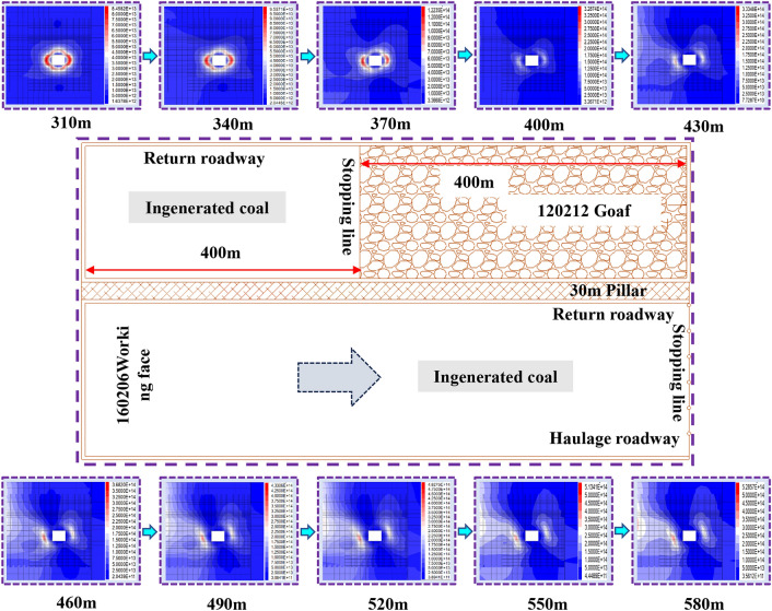
In this paper, FLAC3D numerical model is established based on the engineering background of 120,212 and 160,206 working face in Yangchangwan. The dimensions of the model in X, Y and Z directions are 850 m, 1170 m and 150 m, respectively. The whole model is composed of 1,634,270 grids, of which 160,206 return air roadway is meshed, and the double yield model is used to fill the goaf. When the working face of the upper section is advanced, the J2 distribution cloud map of 160,206 return air roadway is shown in Fig. 11.
Fig. 11.
J2 distribution cloud diagram of surrounding rock of return air roadway after advancing of 120,212 working face.
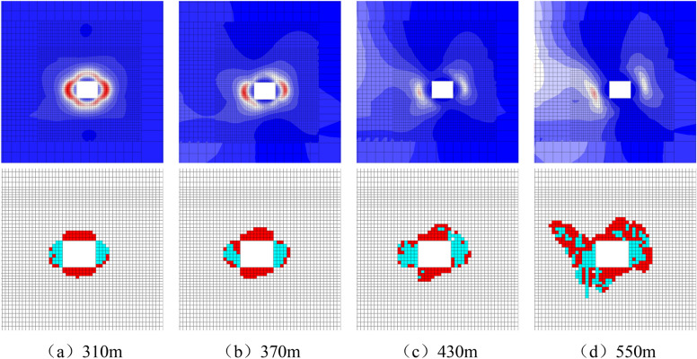
When the left side of the return air roadway is 120,212 solid coal area, the mining roadway is less affected by the abutment pressure of the lateral goaf, and the J2 stress concentration degree of the surrounding rock of the roadway is low and basically presents a uniform and symmetrical ‘oval’ distribution; when the left side of the return airway is 120,212 solid coal-goaf transition area, the J2 stress concentration of the surrounding rock of the roadway gradually increases due to the combined influence of the lateral goaf abutment pressure and the original rock stress. When the return airway is 370 m away from the open-off cut, the J2 stress form gradually changes from ‘oval’ to ‘butterfly’. Due to the stress deflection, the J2 butterfly leaf gradually deflects to the side of the goaf, and the J2 stress changes from the uniform and symmetrical distribution of the solid coal stage to the non-uniform and asymmetric distribution. The stress is mainly concentrated in the coal pillar side and the floor near the coal pillar side, as well as the coal wall side and the roof near the coal wall side. When the left side of the return air roadway is 120,212 goaf area, the joint influence of lateral abutment pressure and original rock stress is intensified. At this time, the concentration degree of J2 stress butterfly leaf is increasing, and the J2 stress form is gradually changed from ‘butterfly’ to ‘butterfly’, and the deflection angle of stress butterfly leaf remains basically unchanged. At the same time, the J2 stress butterfly leaf on the side of the coal wall is stably expanded, and the stress concentration degree is gradually transferred from the shallow part to the deep part. The J2 stress butterfly leaf on the side of the coal pillar and the J2 stress in the lateral goaf are connected in a large range, and the instability of the butterfly leaf stress is generated. Rapid expansion is not conducive to the stability of the surrounding rock of the roadway. With the increase of the distance from the open-off cut, although the’butterfly shape’ has different expansion ranges, it basically remains unchanged in shape.
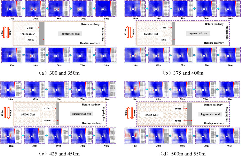
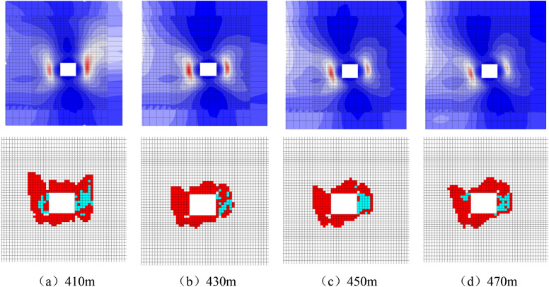
The J2 distribution cloud diagram of 160,206 return airway under different working face advancement is shown in Fig. 12. In the process of 160,206 working face gradually advancing towards 120,212 goaf area, the surrounding rock J2 of roadway is always under the influence of high deviatoric stress environment. At the 10 m position of the advanced working face, J2 has different degrees of stress concentration in the coal pillar side and the coal wall side. With the increase of the distance of the advanced working face, J2 is mainly affected by the complex superposition of the abutment pressure of the lateral goaf and the mining stress in front of the working face. Its morphological evolution law is basically the same as that of the excavation influence stage. At this stage, the roadway coal pillar side and its floor, coal wall side and its surrounding rock within the roof range have obvious J2 stress concentration. This is inevitably related to the monitoring results of the surrounding rock of the roadway, that is, the roof of the coal pillar, the floor of the coal wall and the non-uniform deformation and failure of the two sides.
Fig. 12.
J2 distribution cloud diagram of surrounding rock of return air roadway under different advance degrees.
Based on the close relationship between the distribution pattern of the second invariant J2 of the deviatoric stress tensor and the distribution pattern of the plastic zone obtained from the above analysis, that is, when the distribution of J2 in the surrounding rock of the roadway presents ‘circular’, ‘elliptical’ and ‘butterfly’, the plastic zone of the surrounding rock of the roadway also presents a corresponding consistent shape. Based on the analysis of the dynamic distribution law of J2 and the evolution law of the plastic zone in the surrounding rock of the roadway under the deviatoric stress field, the J2 and the plastic zone morphology at different positions of the return air roadway from the open-off cut before and after the advance of the 160,206 working face are selected, as shown in Figs. 13 and 14. The law between J2 and plastic zone of roadway surrounding rock in shape and direction during excavation and mining is compared and analyzed, and the non-uniform failure mechanism of roadway surrounding rock during excavation is revealed.
Fig. 13.
Comparison of J2 and plastic zone distribution when 160,206 working face advances 400 m.
Fig. 14.
Comparison of J2 and plastic zone morphology at different positions when 160,206 working face advances 400 m.
From the diagram, it can be seen that the 160,206 return air roadway is affected by the 120,212 lateral goaf at different positions in the mining influence stage such as excavation and mining. There are three forms of ‘oval’, ‘butterfly’ front state and ‘butterfly’ in the surrounding rock J2 of the roadway. Among them, the ‘butterfly’ front state and ‘butterfly’ form are non-uniformly and asymmetrically distributed, and the corresponding surrounding rock plastic zone also has three forms of ‘oval’, ‘butterfly’ front state and ‘butterfly’. And the plastic zone of surrounding rock deflects in the same direction and angle with the deflection of J2 stress. Therefore, there is a one-to-one correspondence between J2 stress and plastic zone in the form and direction of mining roadway surrounding rock under deviatoric stress field, and the depth of stress concentration and plastic zone development is basically consistent.
Surrounding rock control technology program
Based on the above analysis, the surrounding rock control idea of’whole-part-region’ three-dimensional integration of mining roadway under partial stress field is put forward22,23:
-
Regulating the high deviatoric stress environment of the roadway to prevent the formation of J2 stress concentration in the roadway. The main measures include:
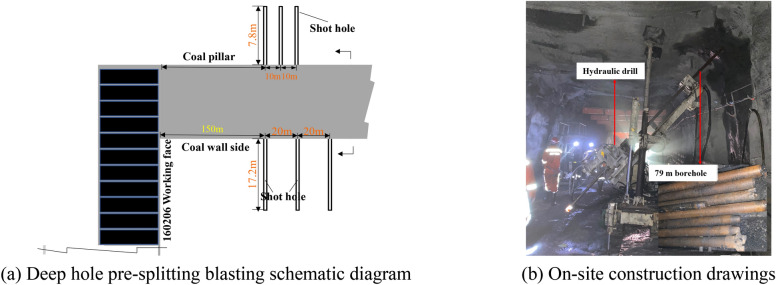
The parameters of deep hole pre-splitting blasting are shown in Fig. 15. Firstly, a deep hole pre-splitting blasting pressure relief drilling field is arranged every 20 m on the side roof of the coal wall. Three holes are constructed in each drilling field. The diameter of the hole is 79 mm, the depth of the hole is 30 m, and the hole is about 1 m from the side of the roadway. The three holes are perpendicular to the direction of the roadway, and the drilling is carried out along the elevation angle of 55°, 65° and 75° respectively. The charge of each hole is 25 kg, 28 kg and 30 kg respectively, and the length of the hole is not less than 10 m. On the side roof of the coal pillar, a deep hole pre-splitting blasting pressure relief drilling field is arranged every 10 m, and one hole is constructed in each drilling field. The hole diameter is 79 mm and the hole depth is 30 m. The hole mouth is about 1m away from the roadway side, the borehole is perpendicular to the direction of the roadway, the elevation angle is 75°, the charge of each borehole is 25 kg, and the sealing length is not less than 10 m.
According to the development degree and range of the plastic zone of the surrounding rock of the roadway, the sensitive position of the roadway section is strengthened and the anchoring end of the supporting body is in the elastic zone of the rock mass. The asymmetric long and short bolt (cable) coordinated strengthening support can not only improve the stress state of the shallow surrounding rock, inhibit the malignant expansion of the butterfly wing in the plastic zone, but also make the roadway maintain unified coordinated deformation and stability. On the basis of the advanced deep hole pre-splitting blasting of the surrounding rock of the roof as a whole, the surrounding rock of the local roadway is still seriously deformed, showing serious drums on both sides. The bottom heave of the coal pillar side is greater than that of the coal wall side, and the subsidence of the coal wall side roof is greater than the non-uniform deformation and failure characteristics of the coal pillar side. In view of the’butterfly’ non-uniform distribution of the plastic zone of the surrounding rock under the mining-induced deviatoric stress field, the existing roof support is a non-uniform support method with the center of the roadway as the symmetrical axis and the side support of the coal pillar greater than the side support of the coal wall. While bearing serious costs, it does not provide good support for the surrounding rock of the roadway, and the deformation of the surrounding rock of the roadway is large. Based on the existing roadway support, it is proposed to strengthen the coordinated support of asymmetric long and short anchor cables in the local area of the surrounding rock section of the roadway. The main support parameters are shown in Table 3 and Fig. 16.
Fig. 15.
Deep hole pre-splitting blasting pressure relief hole layout.
Table 3.
Strengthening support parameters.
| No | Anchor cable size | Type and quantity of anchoring agent | The specific location and number of supplementary hits |
|---|---|---|---|
| 1 | φ28.6 mm × 8300 mm | K2870 (2), Z2870 (2) | One every 2 m along the roadway strike |
| 2 | φ28.6 mm × 8300 mm | K2870 (2), Z2870 (2) | Along the direction of the maximum development depth of the plastic zone, 1 root is added every 2 m |
| 3 | φ21.8 mm × 6300 mm | K2370 (1), Z2370 (2) | Coal wall side and coal pillar side |
Fig. 16.
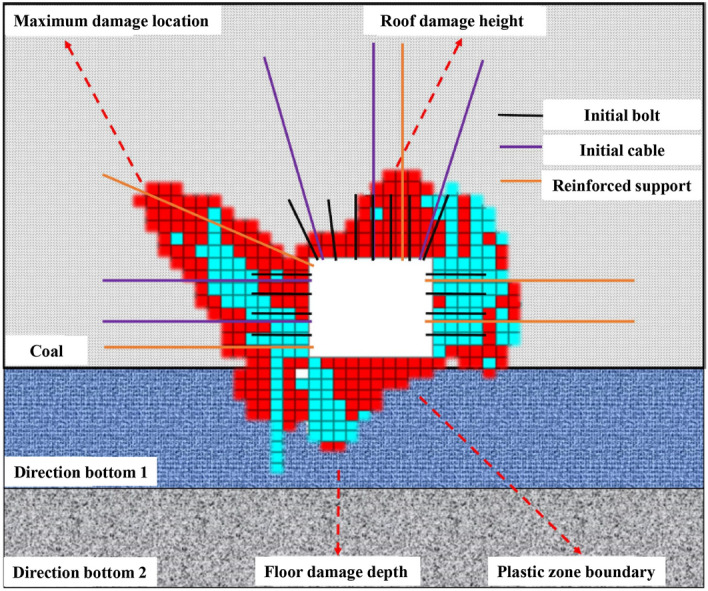
Roadway strengthening support diagram.
In order to verify the rationality of the support scheme and the pressure relief of the borehole, the surface displacement of the roadway was monitored in the return air roadway of 160,206 working face. The field engineering test results show that the J2 stress field shape is regulated by the deep hole pre-splitting blasting of the roof, the malignant expansion of the butterfly wing in the plastic zone is inhibited by the asymmetric long and short anchor cable, the hidden danger of roof fall in the key area is eliminated by the pumping pillar and the non-repeated support unit support, the deformation of the roadway roof is effectively reduced, and the safe and efficient production of the working face is guaranteed.
Conclusions
The expression of the second invariant J2 of deviatoric stress at any point around the surrounding rock of circular roadway under non-uniform stress field is obtained. It is found that the distribution of J2 under different stress environments will appear in three forms: ‘circular’, ‘oval’ and ‘butterfly’.
The distribution pattern of the second invariant J2 of deviatoric stress is closely related to the distribution pattern of plastic zone. When the distribution of surrounding rock J2 presents ‘circular’, ‘elliptical’ and ‘butterfly’, the plastic zone presents a corresponding consistent shape.
When the second invariant of deviatoric stress J2 generates stress concentration, the surrounding rock of roadway will produce large-scale damage. When the degree of stress concentration is high, it may lead to the malignant expansion of surrounding rock of roadway.
The distribution of the second invariant J2 of deviatoric stress is directional. When the principal stress rotates over a certain angle, the second invariant J2 of deviatoric stress and plastic zone also rotate over the same angle.
Under the influence of superimposed mining, the second invariant deviatoric stress J2 in the wind lane of 160,206 working face in Yangchangwan presents a butterfly distribution, and the stress butterfly leaves show a certain degree of rotation. Based on the failure form of plastic zone, the corresponding optimized support scheme is proposed, and the engineering effect is well applied.
Acknowledgements
This research was funded by the China Academy of Safety Production Science Basic Research Business Funding Special Funding (Grant Number: 2023JBKY12).
Author contributions
TH: conceptualization and methodology, HT: methodology and writing—original draft, SG and BT: supervision and conceptualization, and SY: investigation and data curation.
Data availability
The datasets generated and/or analyzed during the current study are available from the corresponding author upon reasonable request.
Competing interests
The authors declare no competing interests.
Footnotes
Publisher’s note
Springer Nature remains neutral with regard to jurisdictional claims in published maps and institutional affiliations.
References
- 1.Peng, M. L., He, M. C., Xiao, Y. M., Cheng, T. & Qiao, Y. F. Asymmetric failure behavior of surrounding rock in the deep roadway: A semi-analytical solution. Eng. Fail. Anal.160, 108075. 10.1016/j.engfailanal.2024.108075 (2024). [Google Scholar]
- 2.Liu, H. T. et al. Nonlinear empirical failure criterion for rocks under triaxial compression. J. China Univ. Mining Technol.34(03), 351–369. 10.1016/j.ijmst.2024.03.002 (2024). [Google Scholar]
- 3.Liu, H. T. et al. Strength and damage evolution mechanism of rock mass with holes under cyclic loading. J. Cent. S. Univ.31, 2717–2735. 10.1007/s11771-024-5714-4 (2024). [Google Scholar]
- 4.Liu, H. T. et al. Mechanism of non-uniform expansion and stability control in surrounding rock failure zone due to superimposed mining. J. Mining Saf. Eng.41(03), 522–532. 10.13545/j.cnki.jmse.2022.0355 (2024). [Google Scholar]
- 5.Liu, H. T. et al. Research on energy evolution law and control method of deformation of high stress roadway surrounding rock. J. China Coal Soc.1, 1–15. 10.13225/j.cnki.jccs.2023.1364 (2024). [Google Scholar]
- 6.Wu, X. Y. et al. Temporal-spatial evolutionary law of plastic zone and stability control in repetitive mining roadway. J. China Coal Soc.45(10), 3389–3400. 10.13225/j.cnki.jccs.2019.1051 (2020). [Google Scholar]
- 7.Huang, B. X. et al. Large deformation theory of rheology and structural instability of the surrounding rock in deep mining roadway. J. China Coal Soc.45(03), 911–926. 10.13225/j.cnki.jccs.SJ19.1451 (2020). [Google Scholar]
- 8.Feng, G. Y. et al. Asymmetric deformation mechanism and control measures for mining roadway under roadway under gob in close proximity. J. China Univ. Mining Technol.51(04), 617–631. 10.13247/j.cnki.jcumt.001375 (2022). [Google Scholar]
- 9.Zhao, H. B. et al. Distribution characteristics of deviatoric stress field and failure law of roadway surrounding rock under non-hydrostatic pressure. J. China Coal Soc.46(02), 370–381. 10.13225/j.cnki.jccs.2020.1877 (2021). [Google Scholar]
- 10.He, F. L. & Zhang, G. C. Stability analysis and control of deep underground roadways subjected to high horizontal tectonic stress. J. China Univ. Mining Technol.44(03), 466–476. 10.13247/j.cnki.jcumt.000345 (2015). [Google Scholar]
- 11.Wang, E. et al. Distribution laws and control of deviatoric stress of surrounding rock in the coal roadway under intense mining. J. Mining Saf. Eng.38(02), 276–285. 10.13545/j.cnki.jmse.2020.0445 (2021). [Google Scholar]
- 12.Ma, N. J., Li, J. & Zhao, Z. Q. Distribution of the deviatoric stress field and plastic zone in circular roadway surrounding rock. J. China Univ. Mining Technol.44(02), 206–213. 10.13247/j.cnki.jcumt.000309 (2015). [Google Scholar]
- 13.Yu, W. J., Wu, G. S., Yuan, C., Wang, P. & Du, S. H. Failure characteristics and engineering stability control of roadway surrounding rock based on deviatoric stress field. J. China Coal Soc.42(06), 1408–1419. 10.13225/j.cnki.jccs.2016.1117 (2017). [Google Scholar]
- 14.Shi, H. Y. Mechanics Mechanism and its Quantitative Analysis of the Formation of Longmenshan Faults 42–43 (China University of Mining & Technology, 2021). [Google Scholar]
- 15.Zheng, Y. T. Simplified model of three-dimensional stress field around borehole and roadway. J. China Coal Soc.4, 74–80. 10.13225/j.cnki.jccs.1982.04.008 (1982). [Google Scholar]
- 16.Shang, F. L. Fundamentals of Plastic Mechanics (Xi’an Jiaotong University Press, 2015). [Google Scholar]
- 17.Xu, L. Distribution and Application of Tloor Deviatoric Stress Tensor Invariants Under Close-Distance Multiple Pillars 11–13 (China University of Mining & Technology, 2014). [Google Scholar]
- 18.Zhao, Z. Q. Mechanism of Surrounding Rock Deformation and Failure and Control Method Research in Large Deformation Mining Roadway 24–28 (China University of Mining & Technology, 2014). [Google Scholar]
- 19.Zhao, Z. Q., Ma, N. J., Liu, H. T. & Guo, X. F. A butterfly failure theory of rock mass around roadway and its application prospect. J. China Univ. Mining Technol.47(05), 969–978. 10.13247/j.cnki.jcumt.000922 (2018). [Google Scholar]
- 20.Guo, X. F., Ma, N. J., Zhao, X. D. & Li, Y. E. General shapes and criterion for surrounding rock mass plastic zone of round roadway. J. China Coal Soc.41(8), 1871–1877. 10.13225/j.cnki.jccs.2016.0787 (2016). [Google Scholar]
- 21.Li, J., Qing, X. B., Ma, N. J., Zhang, R. G. & Li, B. Formation mechanism and engineering application of the directionality of butterfly leaf in the butterfly plastic zone of roadway rock surrounded. J. China Coal Soc.46(09), 2838–2852. 10.13225/j.cnki.jccs.2021.1150 (2021). [Google Scholar]
- 22.Huo, T. H. Non-uniform Failure Mechanism and Stability Control of Mining Roadway Under Deviatoric Stress Field (China University of Mining & Technology, 2022). [DOI] [PMC free article] [PubMed] [Google Scholar]
- 23.Liu, H. T. et al. Low sensitivity research and engineering application of roadway butterfly failure strength criterion. Rock Soil Mech.45(01), 117–130. 10.27624/d.cnki.gzkbu.2022.000186 (2024). [Google Scholar]
Associated Data
This section collects any data citations, data availability statements, or supplementary materials included in this article.
Data Availability Statement
The datasets generated and/or analyzed during the current study are available from the corresponding author upon reasonable request.


