Abstract
This paper presents novel MIMO microstrip patch antennas with dimensions of 40 × 80 × 1.6 mm³ incorporating a decoupling and pattern correction structure (DPCS) designed to mitigate mutual coupling and radiation pattern distortion, operating within 3.6–3.7 GHz. Using characteristic mode analysis (CMA), two key modes affecting coupling and pattern degradation are identified, with the DPCS strategically positioned to address these issues. Unlike other decoupling techniques, the DPCS requires no additional space or structural complexity, making it suitable for 5G MIMO systems. The proposed design achieves isolation up to 90 dB and enhances the realized gain of Port 2 by 3 dB at boresight in simulations. Fabricated antennas were measured, achieving peak isolation of 80 dB in an anechoic chamber. Additionally, measurements in a noisy environment confirmed the robustness of the design under realistic conditions. Measured radiation patterns verified the DPCS’s ability to correct the radiation pattern. Key MIMO performance metrics, including ECC (2 × 10⁻⁴), DG (≈ 10), CCL (< 0.2 bits/s/Hz), MEG (≈ -7 dB), and TARC (< -12 dB), affirmed the design’s superior performance. The proposed structure can be applied to a variety of applications such as high-density urban wireless networks and IoT systems, where maintaining high isolation and reliable communication are critical requirements.
Keywords: Characteristic mode analysis, Decoupling structure, Microstrip patch antenna, Mutual coupling, Pattern correction
Subject terms: Engineering, Electrical and electronic engineering
Introduction
Multiple-Input-Multiple-Output (MIMO) is a wireless technology that boosts the performance of wireless communication networks using multiple antennas at both the transmitting and receiving ends. MIMO has the ability to enhance data rates, reliability, and channel capacity in wireless communications without the need for additional power or spectra1–5. For this reason, MIMO is a key technology in 5G communications due to the increasing demand for intelligent services and higher data rates6–12. However, a major problem in developing this system is the strong mutual coupling between antennas, which negatively impacts system performance. The mutual coupling between antennas, induced by surface currents on the ground plane and space waves in free space, leads to an increase in the correlation between the signals received at the separate ports, which reduces the diversity gain, channel capacity, and mean effective gain13–17. This increased coupling can lead to signal distortion and interference from adjacent antennas, further degrading system performance. Therefore, suppression of mutual coupling is essential for reliable MIMO performance and high-quality signal transmission in modern wireless communication systems18–21.
Numerous researchers have suggested decoupling techniques for MIMO antennas22–29. Frequency selective surface (FSS)22and metasurfaces23,24can effectively enhance the isolation between MIMO antennas or modify their radiation patterns. However, these techniques require additional space around the MIMO antennas, leading to an increase in the overall antenna volume. Moreover, these decoupling designs are complex, and setup of the structures above the antennas is intricate. In addition to these techniques, parasitic patches25, defected ground structure (DGS)26, and electromagnetic bandgap (EBG)27–29are promising candidates for decoupling structures. While these techniques do not require additional space, the referenced decoupling designs are often complex22–24,26,28. Even when the decoupling designs are simple25,27, they lack crucial performance metrics for MIMO applications, such as envelope correlation coefficient (ECC), channel capacity loss (CCL), total active reflection coefficient (TARC), and mean effective gain (MEG). These methods have not demonstrated reliable performance for MIMO applications. Unlike the referenced studies, this research utilizes characteristic mode analysis (CMA) to accurately identify and address the root causes of mutual coupling and radiation pattern distortion. By utilizing CMA, the proposed design provides a systematic design approach to decoupling and radiation pattern correction, ensuring precise and effective solutions to these critical issues. This analytical approach distinguishes the study from prior works and demonstrates its contribution to advancing the MIMO antenna systems for 5G and next-generation wireless applications.
To enhance isolation initially and ensure spatial and polarization diversity, microstrip patch antennas are arranged orthogonally, utilizing orthogonal polarization, as in Fig. 1. However, this arrangement leads to deterioration of the radiation pattern of the microstrip patch antenna (labeled Port 2) due to excitation of a specific mode on the ground. To mitigate the mutual coupling and deformation of the radiation pattern of Port 2, we analyzed the overall structure using CMA. Through this analysis, we identified significant detrimental characteristic modes that lead to mutual coupling and radiation pattern deformation. To mitigate these problems, we proposed a novel decoupling structure, referred to as the decoupling and pattern correction structure (DPCS). This structure is strategically positioned at critical locations, causing mutual coupling and radiation pattern distortion. The proposed DPCS modifies the characteristic modes that initially cause mutual coupling and distort the radiation pattern. These characteristic modes are transformed into new modes that no longer distort the radiation pattern of Port 2 while minimizing mutual coupling. Implementing this structure achieves isolation up to 80 dB between the two patch antennas in an anechoic chamber and simultaneously corrects the radiation pattern with enhancement of the realized gain of Port 2 by approximately 3 dB at the boresight. Additionally, measurements were also conducted in a noise-rich environment, confirming that the proposed design maintains high isolation and consistent MIMO performance under realistic conditions.
Fig. 1.
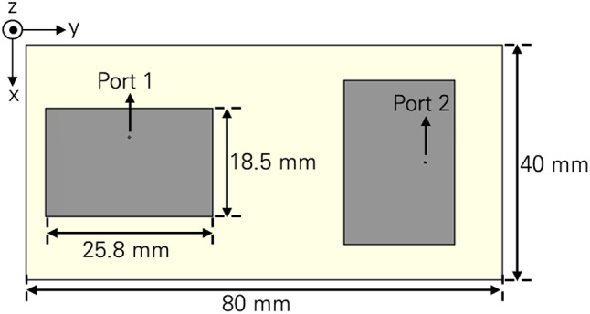
Schematics of the initial microstrip patch antennas.
The remainder of this paper is organized as follows. Section 2 presents the design and simulated results of the perpendicularly arranged initial microstrip patch antennas, which operate in the sub-6 GHz band (3.6 –3.7 GHz). This includes an analysis of the mutual coupling and radiation pattern deterioration. Based on these findings, the design of the CMA-based DPCS is introduced to mitigate the mutual coupling and radiation pattern distortion, providing an effective solution for enhancing the isolation and overall performance of the microstrip patch antennas. Section 3 validates the proposed MIMO antennas with the DPCS through a comparison of simulated and measured results, along with a discussion of the MIMO performance of the proposed antennas. Finally, concluding remarks are provided.
Methods
Initial microstrip patch antennas
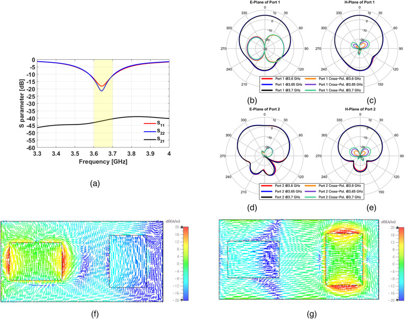
Figure 1illustrates the microstrip patch antennas designed in this work. The dimensions of patch antennas were 18.5 × 25.8 mm2 (0.22 λ0 × 0.31 λ0) for operation in the sub-6 GHz band (3.6 –3.7 GHz), where λ0 represents the free space wavelength at the center frequency within the operating range. The patch antennas were arranged perpendicular to one another to enhance isolation through orthogonal polarization, ensuring spatial and polarization diversity. The substrate was FR-4 (εr= 4.3, tan δ = 0.025), with dimensions of 40 × 80 × 1.6 mm3 (0.48 λ0 × 0.97 λ0 × 0.019 λ0). The simulation results are illustrated in Fig. 2. Figure 2a shows the S parameters of the initial microstrip patch antennas, Fig. 2b and c present the radiation patterns of Port 1, Fig. 2d and e display the radiation patterns of Port 2, and Fig. 2f and g illustrate the surface current distribution when each port is excited. As shown in Fig. 2a, S11 and S22 were below − 10 dB, and the isolation was about 40 dB. The radiation pattern of Port 2 was null in the boresight, and the maximum realized gain of the Port 2 was generated at ± 30° as depicted in Fig. 2d. As can be seen from Fig. 2g, the cause of mutual coupling can be identified, but recognizing the exact cause of the deterioration in the radiation pattern of Port 2 is not straightforward. The cross-polarization level of the initial microstrip patch antennas was also evaluated. For Port 1, the cross-polarization level in the E-plane was approximately 15 dB, while the H-plane, as well as both the E-plane and H-plane of Port 2, showed around 25 dB. These results indicate relatively high cross-polarization interference in E-plane of Port 1.
Fig. 2.
Simulation results of initial microstrip patch antennas (a) S parameters, (b) E-plane of Port 1, (c) H-plane of Port 1, (d) E-plane of Port 2, (e) H-plane of Port 2, (f) surface current density for Port 1 excitation, and (g) surface current density for Port 2 excitation.
To identify the cause of deterioration of the radiation pattern of Port 2 and further enhance the isolation, these initial microstrip patch antennas were analyzed by characteristic mode analysis (CMA). Based on CMA results, we proposed a novel DPCS.
CMA-based design of DPCS
Characteristic modes provide a framework for describing a set of mutually orthogonal characteristic currents that exist on the surface of a conductor. These modes are intrinsic to the conductor and are solely determined by its shape and size, independent of any external excitations. The actual current (denoted as J) on the antenna conductor surface can be represented as a linear combination of these characteristic mode currents (Jn) as follows30–34:
 |
1 |
This equation expresses the total current on the antenna’s surface as a linear combination of individual characteristic modes. Each mode represents a specific surface current distribution on the conductor, allowing for detailed analysis of how different configurations contribute to the antenna’s overall physical behavior.
In this context,  represents the modal weighting coefficient (MWC) for each mode, indicating the contribution of each mode to the overall electromagnetic response generated by a specific source35–40. Specifically, the antenna designers can predict how different modes influence the overall current distribution on the antenna surface.
 |
2 |
Here r is the observation point, Ei is the incident electric field, “tan” denotes the tangential component of the electric field, and λ represents the eigenvalue.
Based on the equation of MWC, the magnitude of the denominator is referred to as modal significance (MS) as shown in Eq. (3). MS describes how dominant a particular mode is in terms of its response. Modes with higher MS values (MS ≥ 0.707) are more influential in shaping the antenna’s radiation pattern and isolation characteristics, offering insights into which modes should be emphasized or suppressed for desired performance41–46.
 |
3 |
The CMA is particularly effective in antenna design because it provides clear and direct insight into the radiation characteristics on the antenna surface. This capability enables a more systematic and informed approach to antenna design, ultimately improving performance.
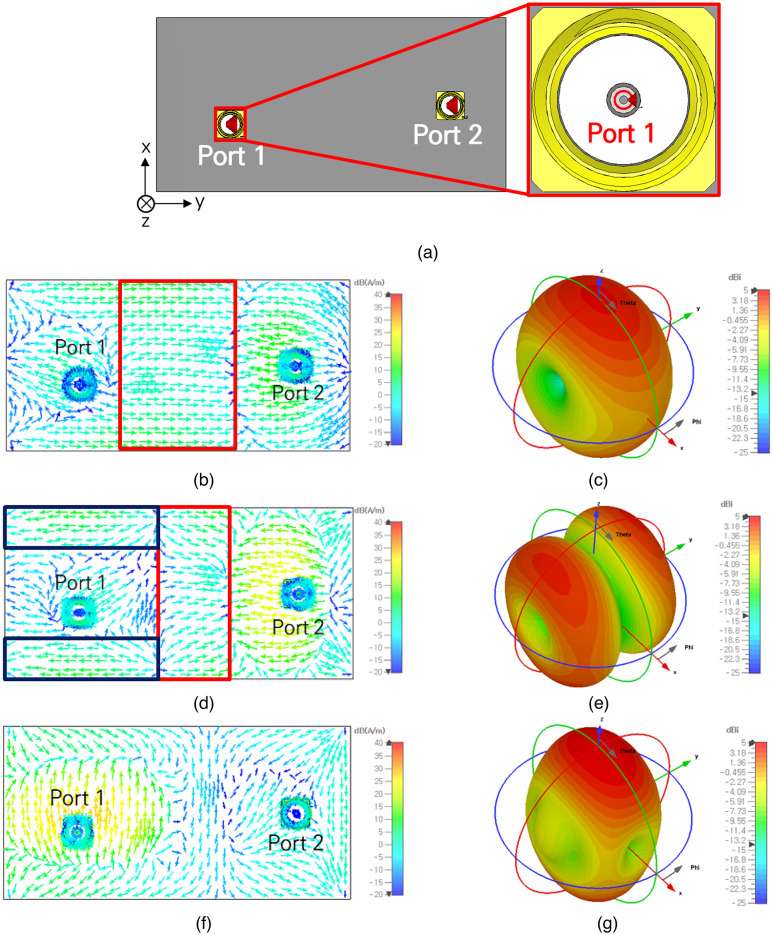
To identify the cause of the mutual coupling and the deformed radiation pattern, the initial microstrip patch antennas were analyzed using the CMA method. As shown in Figs. 3 and 4, three modes—Mode 1, Mode 2, and Mode 3—were identified. The CMA was conducted using the integral equation solver, based on the Method of Moments (MoM), embedded in CST Studio Suite 2024. This solver was chosen for its ability to analyze characteristic modes on the conductor’s surface accurately. To simulate the characteristic modes and obtain the MS and MWC results, planar discrete ports were applied to each coaxial cable, as shown in Fig. 3a. The simulation results enabled us to identify the specific characteristic modes contributing to mutual coupling and radiation pattern distortion, forming the basis for the development of the proposed DPCS. Figure 3b, d, and f illustrate the surface current distributions for Modes 1, 2, and 3, respectively, while Fig. 3c, e, and g present the corresponding radiation patterns. Figure 4a shows the MS of the initial microstrip patch antennas, and Fig. 4b and c depict the MWC of Port 1 and Port 2, respectively. Mode 1, excited by both Port 1 and Port 2 as seen in Fig. 4b and c, contributed to mutual coupling through the horizontal current distribution formed between the two ports, as indicated by the red line in Fig. 3a. Mode 2, solely excited by Port 2 as shown in Fig. 4c, caused mutual coupling through the horizontal current flow between the two ports, marked with a red line, and contributes to deformation of the radiation pattern, as indicated by the blue line in Fig. 3c. This resulted in a problematic radiation pattern as depicted in Fig. 3d. Mode 3, which is only excited by Port 1 as seen in Fig. 4b, contributes to the radiation pattern of Port 1, as shown in Fig. 3f.
Fig. 3.
Simulation setup, surface current density and radiation patterns of initial microstrip patch antennas (a) simulation setup for CMA, (b) surface current density of Mode 1, contributing to mutual coupling (red line), (c) radiation pattern of Mode 1, (d) surface current density of Mode 2, contributing to mutual coupling (red line) and radiation pattern distortion of Port 2 (blue line), (e) radiation pattern of Mode 2, illustrating its contribution to the radiation pattern of Port 2, (f) surface current density of Mode 3, and (g) radiation pattern of Mode 3.
Fig. 4.
CMA results of initial microstrip patch antennas (a) MS, (b) MWC of Port 1, and (c) MWC of Port 2. These results emphasize the dominant modes contributing to mutual coupling between two ports and radiation pattern distortion of Port 2 within the operating frequency range.
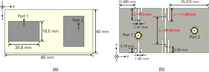
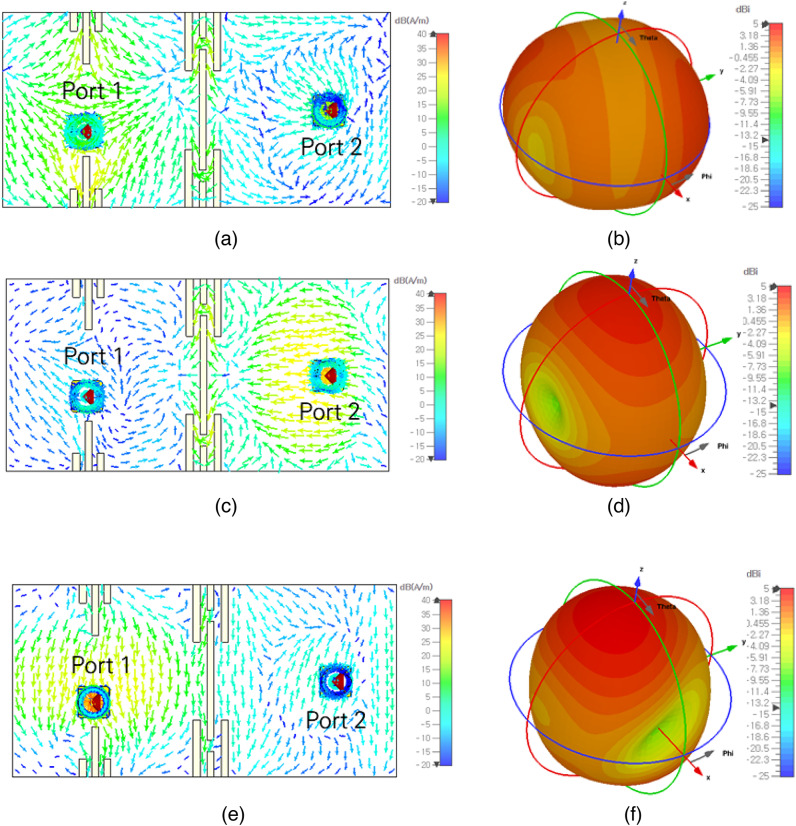
Based on these results, we propose a novel DPCS to simultaneously mitigate the two issues. Figure 5a shows the top view of the microstrip patch antennas, and Fig. 5b illustrates the ground plane with the proposed DPCS. The proposed DPCS was designed and strategically positioned at critical locations to mitigate these issues by diminishing the formation of the problematic surface currents of the specific characteristic modes, reducing mutual coupling and correcting the deformed radiation pattern. As illustrated in Figs. 6 and 7, the surface currents, radiation patterns, MS, and MWC for each mode were changed by application of the DPCS. Figure 6 presents the surface current distributions and radiation patterns for Modes 1+, 2+, and 3+, while Fig. 7a shows the MS, and Fig. 7b and c illustrate the MWC values of Port 1 and Port 2 for the transformed modes, respectively. For Mode 1+, Fig. 6a and b show the surface current and radiation pattern, respectively. As can be seen from Fig. 6a, horizontal current flows between the two ports were almost eliminated, resulting in a significant reduction of mutual coupling. Although the radiation pattern of Mode 1+ is not ideal for microstrip patch antennas, as shown in Fig. 6b, its impact on the overall radiation pattern of Port 1 was minimal due to the significantly lower MS and MWC values, as depicted in Fig. 7a and b. In Mode 2+, the horizontal surface current that previously caused mutual coupling was greatly reduced, as illustrated in Fig. 6c. Moreover, no surface current distribution, which contributes to the deformed radiation pattern in Fig. 4 (indicated by the blue lines) was formed, as shown in Fig. 6c. This change led to a substantial improvement in the radiation pattern, as shown in Fig. 6d, where the previously existing null in the boresight direction was eliminated, and the maximum realized gain was achieved near the boresight. Finally, Mode 3+ retains characteristics very similar to the original Mode 3, with the surface current direction aligning closely with the orientation of the proposed DPCS, as shown in Fig. 6e and f.
Fig. 5.
Schematics of the proposed microstrip patch antennas with the novel DPCS (a) top view showing the dimensions of the patch antennas and substrate, and (b) bottom view illustrating the placement and dimensions of the DPCS.
Fig. 6.
Surface current density and radiation patterns of the proposed microstrip patch antennas with the novel DPCS (a) surface current density of Mode 1+, (b) radiation pattern of Mode 1+, (c) surface current density of Mode 2+, (d) radiation pattern of Mode 2+, (e) surface current density of Mode 3+, and (f) radiation pattern of Mode 3+. The results demonstrate a significant reduction in mutual coupling between the two ports, particularly for Mode 1+ and Mode 2+. Additionally, the results for Mode 2+ indicate a correction in the radiation pattern, leading to enhanced performance of Port 2.
Fig. 7.
CMA results of the proposed microstrip patch antennas with the novel DPCS compared to the original modes . (a) MS, (b) MWC of Port 1, and (c) MWC of Port 2. The results demonstrate the effectiveness of the DPCS in mitigating mutual coupling between the two ports.
To optimize the performance of the proposed DPCS, a detailed parametric study was conducted by varying the key structural parameters L, LC, LT, as indicated for red in Fig. 5b. These parameters directly influence the mutual coupling of the proposed DPCS. By sweeping each parameter within a reasonable range, their individual impacts on the isolation were analyzed.
Effect of L:
The length L, which defines the horizontal dimension of the DPCS elements located in the center of the ground, was varied from 11.39 mm to 12.89 mm, as shown in Fig. 8a. The optimized value of L = 11.89 mm achieved a peak isolation of 90 dB and minimum isolation of 60 dB within the operating frequency, demonstrating the critical role of this parameter in minimizing mutual coupling.
Fig. 8.
Parametric study for optimizing the proposed DPCS and its effect on S21 (a) L, (b) LC, and (c) LT. The results illustrate the influence of each parameter on isolation performance, demonstrating the optimal values L = 11.89 mm, LC = 24.66 mm, and LT = 10.5 mm for achieving high isolation.
-
2)
Effect of LC and LT:
The length LC which is located in the center of the ground, and LT located on the side of the ground plane near the Port 1 antenna were varied in ranges of 22.66 mm to 25.66 mm and 7.5 mm to 10.5 mm, respectively. LC and LT played essential roles in refining the overall structural optimization of the DPCS. Adjustments to these parameters provided control over the peak isolation performance. Adjustments to these parameters provided control over the peak isolation levels. The optimized values, LC=24.66 mm and LT=10.5 mm, contributed to achieving balanced isolation performance.
These results demonstrate that L is the most dominant parameter for adjusting frequency shift, while LC and LT are crucial for fine-tuning of peak isolation performance.
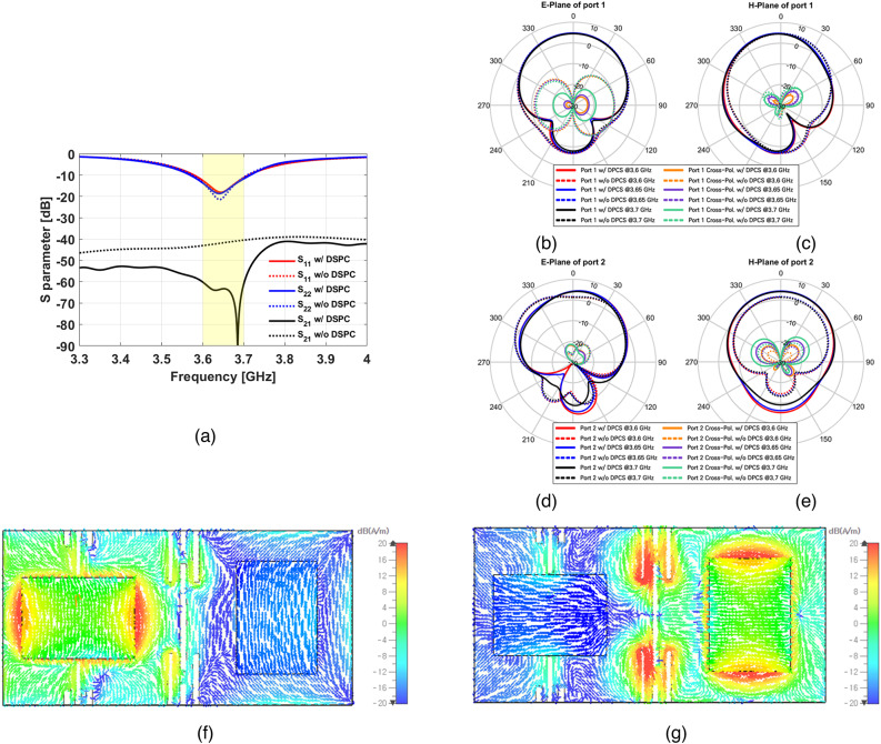
To validate the effectiveness of the proposed microstrip patch antennas with DPCS, the simulated results are presented in Fig. 8. Figure 9a shows the S parameters of the microstrip patch antennas with the proposed DPCS, Fig. 9b and c present the radiation patterns of Port 1, Fig. 9d and e display the radiation patterns of Port 2, and Fig. 9f and g illustrate the surface current distribution when each port is excited. As shown in Fig. 9a, the isolation was up to 90 dB at its peak and 60 dB within the operating frequency range. The realized gain of Port 1 was approximately 4.5 dBi, and Port 2 showed an improvement of about 2.5 to 3 dB at the boresight as shown in Fig. 9b-e. After applying the proposed DPCS, the cross-polarization level of the antennas improved significantly. The cross-polarization level in the E-plane of Port 1 was enhanced by approximately 10 dB. Although a slight increase in cross-polarization level was observed in the H-plane of both Port 1 and Port 2, they still maintained the cross-polarization level around 25 dB. These results demonstrate the effectiveness of the DPCS in reducing polarization interference, particularly in the E-plane of Port 1, while maintaining overall satisfactory performance. Additionally, the overall radiation pattern of Port 2 was corrected by reducing the influence of Mode 2, as can be seen in Fig. 9d. Finally, Fig. 9f and g demonstrate significant suppression of the surface current crossing into the other port compared to the initial results shown in Fig. 2f and g.
Fig. 9.
Simulation results of the proposed microstrip patch antennas with the novel DPCS (a) S parameters showing improved isolation compared to the initial microstrip patch antennas, (b) E-plane of Port 1, (c) H-plane of Port 1, (d) E-plane of Port 2, (e) H-plane of Port 2, (f) surface current density of Port 1 for Port 1 excitation, and (g) surface current density for Port 2 excitation. The results demonstrate reduced mutual coupling and improved radiation patterns with the application of the DPCS.
In the next section, the proposed microstrip patch antennas with the novel DPCS were fabricated and measured to validate the simulation results.
Measurements and Discussion
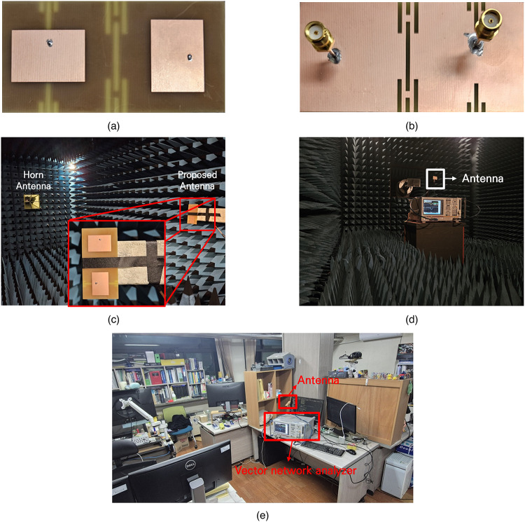
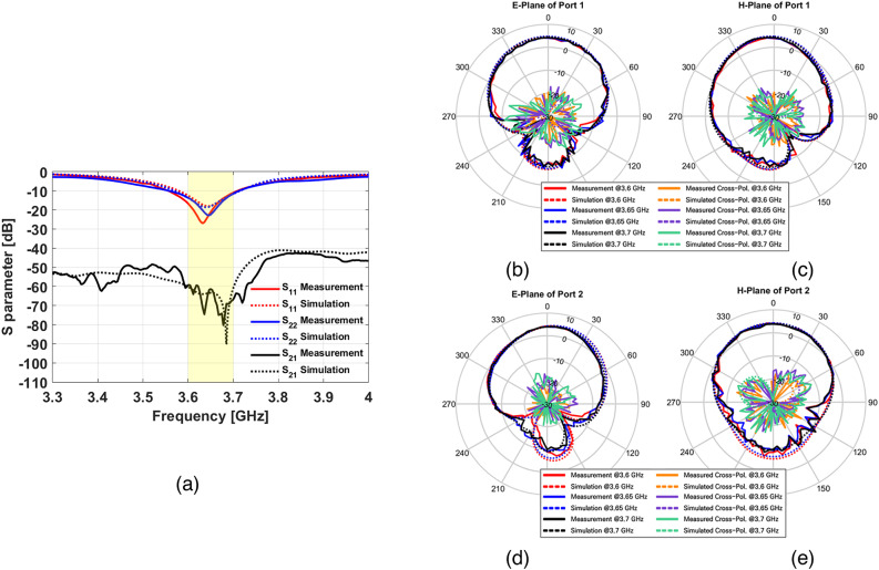
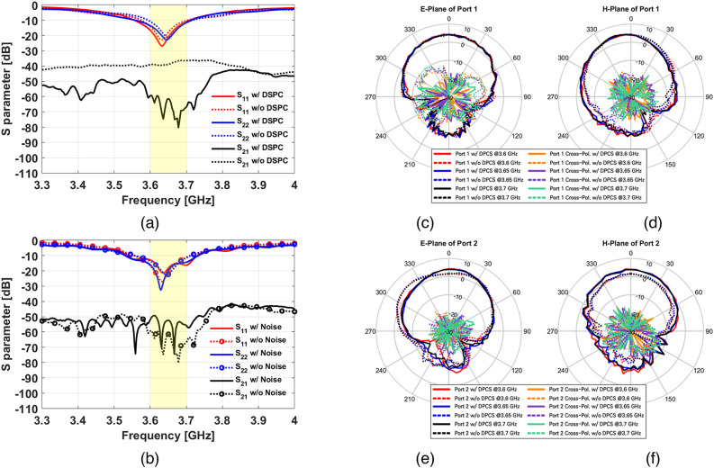
Microstrip patch antennas with the novel DPCS were fabricated, and measurements were conducted to validate the simulation results, as shown in Fig. 10. Figure 10a and b present the fabricated microstrip patch antennas with the novel DPCS. Measurements of radiation patterns and S parameters were performed in the anechoic chamber, as depicted in Fig. 10c and d, respectively. Additionally, S parameters of the proposed microstrip patch antennas were measured in the noisy environment to further validate the effectiveness of the DPCS, as illustrated in Fig. 10e. The noisy environment included various electronic devices, such as computers, cell phones, tablet PCs, etc. All measured results are shown in Figs. 11 and 12. Figure 11a displays the S parameters, while Fig. 11b-e depict radiation patterns for each port. The measured results of the fabricated antennas with DPCS show strong agreement with the simulation results. Figure 12a compares the S parameters of the measured microstrip patch antennas with and without the proposed DPCS. The proposed DPCS significantly reduces mutual coupling, achieving up to 80 dB at its peak and 60 dB within the operating frequency range, as shown in Fig. 12a. Furthermore, the isolation measured in the noisy environment also demonstrates high performance, as illustrated in Fig. 12b. Although slightly reduced compared to the results measured in the anechoic chamber, the maximum isolation reaches 70 dB, and it maintains 50 dB within the operating frequency range. This confirms that the proposed DPCS achieves high isolation performance even in the noisy environment. Moreover, the comparison between the measured results with and without the DPCS also reveals a substantial enhancement in cross-polarization level, particularly for Port 1, while maintaining consistent performance for other planes. In addition, Fig. 12e demonstrates the successful correction of the measured radiation pattern of Port 2, with an improvement in realized gain of approximately 3 dB at the boresight. The realized gain of Port 1 was measured to be approximately 4.5 dBi, consistent with the simulation results, and Port 2 also showed a gain of approximately 4.5 dBi, in strong agreement with the simulated values.
Fig. 10.
Fabricated microstrip patch antennas and measurement setup (a) top view of fabricated antennas, (b) bottom view of fabricated antennas, (c) measurement of radiation pattern setup in the anechoic chamber, including the horn antenna used for testing, (d) measurement of S parameters setup in the anechoic chamber, including the VNA used for testing, and (e) measurement of S parameters setup in the noisy environment, including the VNA used for testing.
Fig. 11.
Comparison between simulated and measured results of the proposed antennas with the novel DPCS (a) S parameters, (b) E-plane of Port 1, (c) H-plane of Port 1, (d) E-plane of Port 2, and (e) H-plane of Port 2. The results demonstrate strong agreement between simulation and measurement, validating the effectiveness of the DPCS in achieving high isolation and radiation pattern correction.
Fig. 12.
Comparison between measured microstrip patch antennas (a) Comparison of S parameters between measured microstrip patch antennas with DPCS and without DPCS, (b) Comparison of S parameters between measured microstrip patch antennas with noise and without noise, (c) E-plane of Port 1, (d) H-plane of Port 1, (e) E-plane of Port 2, and (f) H-plane of Port 2. The results demonstrate the significant improvements in isolation and radiation pattern correction achieved by implementing the DPCS.
In addition to these results, ECC, DG, CCL, MEG, and TARC were evaluated to comprehensively assess MIMO performance of the microstrip patch antennas with the proposed DPCS22–25.
1) Envelope Correlation Coefficient (ECC): The ECC measures the degree of correlation between the output signals of MIMO elements. An ideal ECC value is zero, and an acceptable value is less than 0.05. ECC can be calculated using the following equation:
 |
4 |
2) Diversity Gain (DG): The DG indicates the reduction in transmission power when using a diversity scheme. The ideal DG value is 10, with an acceptable value being greater than 9.99. DG can be calculated using ECC as follows:
 |
5 |
3) Channel Capacity Loss (CCL): The CCL quantifies the loss in channel capacity due to correlation between MIMO antenna elements. The ideal value of CCL is zero, while an acceptable value is less than 0.4 bits/s/Hz. CCL can be calculated using Eqs. (6)–(9):
 |
6 |
where.
 |
7 |
 |
8 |
 |
9 |
4) Mean Effective Gain (MEG): The MEG measures how effectively a MIMO antenna collects and focuses power in environments with multiple signal reflections. The MEG value should range from − 3 dB to −12 dB and is calculated as follows:
 |
10 |
5) Total Active Reflection Coefficient (TARC): TARC is crucial for evaluating the performance of MIMO antennas, representing the ratio of reflected to transmitted power. A low TARC value indicates efficient transmission with minimal reflection, signifying good MIMO antenna performance.
 |
11 |
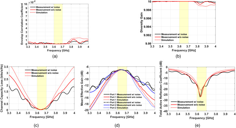
The simulated and measured results of MIMO performance are illustrated in Fig. 13. Figure 13a–e show the ECC, DG, CCL, MEG, and TARC, in that order. All the measured results of MIMO performance closely matched the simulated results within the operating frequency. ECC was lower than 2 × 10⁻⁴, DG was approximately 10, CCL was lower than 0.2 bits/s/Hz, MEG was approximately − 7 dB, and TARC was lower than − 12 dB within the operating frequency range in the anechoic chamber. Additionally, when measured in the noisy environment, ECC remained below 5 × 10⁻⁴, DG was approximately 10, CCL was below than 0.2 bits/s/Hz, MEG was approximately − 7 dB, and TARC was lower than − 12 dB. Based on these results, the proposed antennas with the novel DPCS were highly suitable for sub-6 GHz 5G MIMO systems.
Fig. 13.
MIMO performance comparison between simulation and measurement for (a) ECC, (b) DG, (c) CCL, (d) MEG, and (e) TARC. The results confirm strong agreement between simulated and measured data both in anechoic and noisy environments. The measurements in the noisy environment show slightly degraded but still robust performance, validating the effectiveness of the proposed design in maintaining superior MIMO performance metrics under real-world conditions.
The proposed sub-6 GHz 5G MIMO antennas demonstrate significant improvements compared to recent state-of-the-art designs, as shown in Table 1. None of the referenced designs, except26, offer the function of pattern correction. Although the design in26includes pattern correction, the authors did not provide any results regarding crucial MIMO performance. Therefore, the design in26has not been properly validated for MIMO applications. Additionally, unlike the designs in22–24, the proposed DPCS does not require additional space, and its complexity was notably lower than that of other referenced works. Furthermore, many of the antennas listed in Table 1 were not evaluated for key MIMO metrics such as CCL, MEG, and TARC, which are essential for validating MIMO performance. In contrast, the proposed antennas exhibit superior MIMO performance across all evaluated metrics. Due to their excellent performance, the proposed MIMO antennas are highly advantageous for sub-6 GHz 5G MIMO systems.
Table 1.
Comparison of Sub-6 GHz MIMO antennas.
| Ref. | Technique | Pattern Correction |
Complexity | Extra Space |
Freq. (GHz) (FBW) |
Isolation (dB) | Gain (dBi) |
ECC | CCL (bits/s/Hz) |
TARC (dB) |
MEG (dB) |
|
|---|---|---|---|---|---|---|---|---|---|---|---|---|
| Max. | Min. | |||||||||||
| 22 | FSS | X | Complex | O |
3–6 (66.6%) |
40 | 13 | 7.96 | 4 × 10⁻³ | 0.2 | <−8 | −7.2 ~ −6 |
| 23 |
Meta surface |
X | Complex | O |
2.76–4.3 (43.6%) |
50 | 35 | 10.5 | 10−3 | 0.4 | <−10 | −8.5 ~ −6 |
| 24 |
Meta surface + Reflector |
X | Complex | O |
3.55–3.7 4.4–5 (4.1%, 12.7%) |
30 21 |
20 20 |
7.57 5.6 |
10−2 | 0.4 |
<−4 <−10 |
−14 ~ −7 |
| 25 | Parasitic Patch | X | Simple | X |
4.9–5.06 (3.2%) |
21.3 | 20 | 2 | 5 × 10⁻² | N/A | N/A | N/A |
| 26 | EBG + DGS | O | Complex | X |
3.6–3.7 (3%) |
70 | 52 | 5 | N/A | N/A | N/A | N/A |
| 27 | EBG | X | Simple | X |
5.15–5.35 (3.8%) |
35 | 18 | 5.7 | 3 × 10⁻³ | N/A | N/A | N/A |
| 28 | EBG | X | Complex | X |
2.24–2.42 5.1–5.3 (7.8%, 3.8%) |
21 44.8 |
21 44 |
−1.21 −1.15 |
10−3 | N/A | N/A | N/A |
|
This work |
DPCS | O | Simple | X |
3.58–3.71 (3.6%) |
80 | 60 | 4.3 | 2 × 10⁻⁴ | 0.2 | <−12 | −7.6 ~ −7 |
Conclusion
This paper introduced a novel sub-6 GHz 5G MIMO antenna incorporating a novel DPCS to address the issues of mutual coupling and radiation pattern distortion. The problematic characteristic modes that contribute to these issues were identified utilizing CMA. Based on this analysis, the DPCS was strategically positioned at specific locations to resolve these problems by reducing the generation of the problematic surface currents associated with these modes. The proposed design demonstrated significant improvements, including a peak isolation achievement of up to 90 dB and a realized gain increase of approximately 3 dB at the boresight in the simulation.
The effectiveness of the proposed MIMO antenna was verified through simulations and measurements, which showing strong agreement. Isolation up to 80 dB between the two microstrip patch antennas was achieved, with an average of 60 dB across the operating frequency range. Moreover, measurements conducted in the noisy environment, with various electronic devices, demonstrated high isolation performance, with a maximum isolation of 70 dB and 50 dB within the operating frequency range. These results confirm the robustness of the proposed DPCS in real-world scenarios. Additionally, the boresight gain was enhanced by approximately 3 dB. In addition to excellent isolation and realized gain performance, the proposed design achieved favorable results across key MIMO performance metrics, including ECC (< 2 × 10⁻⁴), DG (≈ 10), CCL (< 0.2 bits/s/Hz), MEG (−7.6 ~ −7 dB), and TARC (< −12 dB) in the anechoic chamber. Furthermore, in the noisy environment, the design maintained robust performance with ECC remaining below 5 × 10⁻⁴, DG at approximately at 10, CCL below 0.2 bits/s/Hz, MEG at around − 7 dB, and TARC under − 12 dB, demonstrating its effectiveness in real-world conditions.
Compared to other state-of-the-art decoupling techniques, the proposed DPCS offers superior performance without the need for additional space or increased structural complexity, making it ideal for sub-6 GHz 5G MIMO systems. The proposed antenna system effectively addresses the growing demand for higher data rates, improved reliability, and efficient use of the wireless spectrum, indicating it as a promising solution for 5G and next-generation wireless communication networks. While the proposed design demonstrates significant advantages, its current optimization for a specific frequency range may limit its applicability to broadband or multi-band systems. Future work could focus on extending the design for broader frequency ranges, improving its scalability for multi-band applications, and enhancing its integration with compact MIMO systems.
Acknowledgements
This work was supported by the National Research Foundation of Korea (NRF) grant funded by the Korea government (MSIT) (No. RS-2024-00409492).
Author contributions
Design, data collection, analysis, and simulation were carried out by M.-J.K. and J.P. The antenna fabrication and measurement were conducted by M.-J.K. and H.H. Additionally, L.Q. addressed the technical concerns about antenna simulation and measurement. K.-Y.J. revised the manuscript and supervised the entire work. All authors contributed to the writing of the manuscript.
Data availability
The datasets used and/or analyzed during the current study are available from the corresponding author upon reasonable request.
Declarations
Competing interests
The authors declare no competing interests.
Footnotes
Publisher’s note
Springer Nature remains neutral with regard to jurisdictional claims in published maps and institutional affiliations.
References
- 1.Mathur, P., Augustine, R., Gopikrishna, M. & Raman, S. Dual MIMO antenna system for 5G mobile phone, 5.2 GHz WLAN, 5.5 GHz WiMAX and 5.8/6 GHz WiFi applications. IEEE Access.4, 1–9 (2016). [Google Scholar]
- 2.Nguyen, T. T., Kim, D., Choi, J. & Jung, C. Circularly polarized series array and MIMO application for sub-millimeter wave/terahertz band. J. Electromagn. Eng. Sci.24 (3), 294–304 (2024). [Google Scholar]
- 3.Lee, H. & Lee, B. Compact broadband dual-polarized antenna for indoor MIMO wireless communications systems. IEEE Trans. Antennas Propag.64 (2), 766–770 (2016). [Google Scholar]
- 4.Tong, C., Yang, N., Leung, K. W. & Liu, G. Design of MIMO antennas with DRAs and a dual-function decoupling/radiating monopole antenna. IEEE Trans. Antenna Propag.72 (5), 3874–3885 (2024). [Google Scholar]
- 5.Khan, S. et al. A compact circularly polarized dielectric resonator antenna with MIMO characterizations for UWB applications. Sci. Rep.14 (22627), 1–21 (2024). [DOI] [PMC free article] [PubMed] [Google Scholar]
- 6.Verma, R. & Sharma, R. Four-element biodegradable substrate-integrated MIMO DRA with radiation diversity. J. Electromagn. Eng. Sci.24 (2), 109–119 (2024). [Google Scholar]
- 7.Kumar, D. R., Babu, G. V., Narayan, K. G. S. & Raju, N. Investigation of 10-port coupled fed slotted MIMO antenna system for 5G mobile handset. Int. J. Microw. Wirel. Technol.14, 892–905 (2021). [Google Scholar]
- 8.Qu, L., Kim, H., Jung, K. Y. & Liu, Y. Compact four-port MIMO antenna module with decoupling components for 5G terminal devices. IEEE Antennas Wirel. Propag. Lett.23 (7), 2224–2228 (2024). [Google Scholar]
- 9.Lee, Y., Choi, S. H., Lee, B. H., Lee, J. Y. & Kim, J. LCP-based low-cost base station antenna for 3.7 GHz 5G band. J. Electromagn. Eng. Sci.24 (3), 276–284 (2024). [Google Scholar]
- 10.Musaed, A. A. et al. High isolation 16-port massive MIMO antenna based negative index metamaterial 5G mm-wave applications. Sci. Rep.14 (290), 1–11 (2024). [DOI] [PMC free article] [PubMed] [Google Scholar]
- 11.Alibakhshikenari, M. et al. An innovative antenna array with high inter element isolation for sub-6 GHz 5G MIMO communication systems. Sci. Rep.12 (7907), 1–13 (2022). [DOI] [PMC free article] [PubMed] [Google Scholar]
- 12.Hussain, N. et al. Dual-sense slot-based CP MIMO antenna with polarization bandwidth reconfigurability. Sci. Rep.13 (16132), 1–10 (2023). [DOI] [PMC free article] [PubMed] [Google Scholar]
- 13.Farahani, M. et al. Mutual coupling reduction in millimeter-wave MIMO antenna array using a metamaterial polarization-rotator wall. IEEE Antennas Wirel. Propag. Lett.16, 2324–2327 (2017). [Google Scholar]
- 14.Kim, S. H. & Chung, J. Y. Analysis of the envelope correlation coefficient of MIMO antennas connected with suspended lines. J. Electromagn. Eng. Sci.20 (2), 83–90 (2020). [Google Scholar]
- 15.Esmail, B. A. F., Isleifson, D. & Koziel, S. Dual-band millimetre wave MIMO antenna with reduced mutual coupling with reduced mutual coupling based on optimized parasitic structure and ground modification. Sci. Rep.14 (20507), 1–16 (2024). [DOI] [PMC free article] [PubMed] [Google Scholar]
- 16.Alfakhri, A. Dual polarization and mutual coupling improvement of UWB MIMO antenna with cross shaped decoupling structure. e-Prime Adv. Electr. Eng. Electron. Energy. 4, 1–10 (2023). [Google Scholar]
- 17.Gerami, H. H., Kazemi, R. & Fathy, A. E. Development of a metasurface-based slot antenna for 5G MIMO applications with minimized cross-polarization and stable radiation patterns through mode manipulation. Sci. Rep.14 (8016), 1–18 (2024). [DOI] [PMC free article] [PubMed] [Google Scholar]
- 18.Farsi, S., Aliakbarian, H., Schreure, D., Nauwelaers, B. & Vandenbosch, G. A. E. Mutual coupling reduction between planar antennas by using a simple microstrip U-section. IEEE Antennas Wirel. Propag. Lett.11, 1501–1503 (2012). [Google Scholar]
- 19.Harbel, M., Zbitou, J., Hefnawi, M. & Latrach, M. Mutual coupling reduction in mmWave patch antenna arrays using mushroom-like EBG structure. in Proc. IEEE 2nd Int. Conf. Electron., Control, Optim, Comput. Sci. (ICECOCS), 1–3 (2020).
- 20.Lee, Y., Ga, D. H., Song, T. & Choi, J. Design of an indoor repeater antenna with the improved isolation using metamaterial absorber. in Proc. IEEE Int. Workshop Antenna Technol. (iWAT), 277–280 (2012).
- 21.Tiwari, R. N., Sharma, D., Singh, P. & Kumar, P. A flexible dual-band 4×4 MIMO antenna for 5G mm-wave 28/38 GHz wearable applications. Sci. Rep.14 (14324), 1–15 (2024). [DOI] [PMC free article] [PubMed] [Google Scholar]
- 22.Zeain, M. Y. et al. A new technique of FSS-based novel chair-shaped compact MIMO antenna to enhance the gain for sub-6GHz 5G applications. IEEE Access.12, 49489–49507 (2024). [Google Scholar]
- 23.Salehi, M. & Oraizi, H. Wideband high gain metasurface-based 4T4R MIMO antenna with highly isolated ports for sub-6 GHz 5G applications. Sci. Rep.14 (14448), 1–19 (2024). [DOI] [PMC free article] [PubMed] [Google Scholar]
- 24.Angadi, S., Sharma, Y., S Raghava, N. & Sabapathy, T. A metasurface based close-proximity two-port circularly polarized MIMO antenna for mid-band sub-6 GHz 5G applications. AEU - Int. J. Electron. Commun.183 (155379), 1–11 (2024). [Google Scholar]
- 25.Masoodi, I. S., Ishteyaq, I. & Muzaffar, K. Extra compact two element sub 6 GHz MIMO antenna for future 5G wireless applications. Prog Electromang Res. Lett.102, 37–45 (2022). [Google Scholar]
- 26.Kang, M. J., Park, S., Cho, K. G. & Jung, K. Y. High-isolation 5G repeater antenna using a novel DGS and an EBG. J. Electromagn. Eng. Sci.23 (3), 275–282 (2023). [Google Scholar]
- 27.Tang, Y. et al. Mutual coupling suppression of MIMO array with non-uniform curved-strip EBG structure via shape and layout co-optimization. AEU – Int. J. Electron. Commun.178 (155306), 1–8 (2024). [Google Scholar]
- 28.Munusami, C. & Venkatesan, R. A compact boat shaped dual-band MIMO antenna with enhanced isolation for 5G/WLAN applications. IEEE Access.12, 11631–11640 (2024). [Google Scholar]
- 29.Kim, S., Kim, D., Kim, Y., Choi, J. & Jung, K. Y. A 24 GHz ISM-band doppler radar antenna with high isolation characteristic for moving target sensing applications. IEEE Antennas Wirel. Propag. Lett.18 (7), 1532–1536 (2019). [Google Scholar]
- 30.Huang, H., Wang, Y. & Luo, J. Analysis and design of compact and high-performance ear-bar TWS earphone antenna with characteristic mode analysis. IEEE Trans. Antennas Propag.71 (9), 7091–7101 (2023). [Google Scholar]
- 31.Khan, R. et al. Enhancing gain and isolation of a quad-element MIMO antenna array design for 5G sub-6 GHz applications assisted with characteristic mode analysis. Sci. Rep.14 (11111), 1–22 (2024). [DOI] [PMC free article] [PubMed] [Google Scholar]
- 32.Li, Z., Wang, S., Li, F., Lin, L. & Zeng, H. An I-shaped slot grid antenna array with substrate integration and enhanced bandwidth. J. Electromagn. Eng. Sci.23 (5), 429–436 (2023). [Google Scholar]
- 33.Wang, J. et al. Characteristic mode inspired broadband circularly polarized folded transmitarray antenna. IEEE Trans. Antennas Propag.71 (9), 7632–7637 (2023). [Google Scholar]
- 34.Song, Z. et al. Design of a miniaturized dual circularly polarized implantable antenna by using characteristic mode method. Sci. Rep.14 (16384), 1–11 (2024). [DOI] [PMC free article] [PubMed] [Google Scholar]
- 35.Chen, Y. & Wang, C. F. Characteristic Modes: Theory and Application to Antenna Engineering (Wiley, 2013). [Google Scholar]
- 36.Harrington, R. F. & Mautz, J. R. Theory of characteristic modes for conducting bodies. IEEE Trans. Antennas Propag.AP-19 (5), 622–628 (1971). [Google Scholar]
- 37.Sathishkumar, N., Palanisamy, S. K., Natarajan, R., Ouahada, K. & Hamam, H. Design of dual mode antenna using CMA and broadband dual-polarized antenna for 5G networks. Sci. Rep.14 (15553), 1–21 (2024). [DOI] [PMC free article] [PubMed] [Google Scholar]
- 38.Wen, D., Hao, Y., Wang, H. & Zhou, H. Design of a wideband antenna with stable omnidirectional radiation pattern using the theory of characteristic modes. IEEE Trans. Antennas Propag.65 (5), 2671–2676 (2017). [Google Scholar]
- 39.Fazal, D., Khan, Q. U. & Hong, I. P. Multiband antenna design with enhanced radiations using characteristic mode analysis. Sci. Rep.13 (17829), 1–14 (2023). [DOI] [PMC free article] [PubMed] [Google Scholar]
- 40.Kang, M. J., Park, D., Kim, G., Kim, S. & Jung, K. Y. Design of stepped monopole antennas with a novel decoupling structure based on characteristic mode analysis. Alexandria Eng. J.111, 482–490 (2024). [Google Scholar]
- 41.Supreeyatitikul, N., Lertwiriyaprapa, T., Krairiksh, M. & Phongcharoenpanich, C. CMA-based four-element broadband circularly polarized octagonal-ring slot antenna array for S-band satellite applications. IEEE Access.10, 130825–130838 (2022). [Google Scholar]
- 42.Elias, B. B. Q., Soh, P. J., Al-Hadi, A. A., Akkaraekthalin, P. & Vandenbosch, G. A. E. A review of antenna analysis using characteristic modes. IEEE Access.9, 98833–98862 (2021). [Google Scholar]
- 43.Supreeyatitikul, N., Janpangngern, P., Lertwiriyaprapa, T., Krairiksh, M. & Phongcharoenpanich, C. CMA-based quadruple-cluster leaf-shaped metasurface-based wideband circularly-polarized stacked-patch antenna array for sub-6 GHz 5G applications. IEEE Access.11, 14511–14523 (2023). [Google Scholar]
- 44.Li, Y., Yang, G., Li, W. & Liu, Q. Dual-band antenna with OAM mode radiated by ground plane. J. Electromagn. Eng. Sci.23 (3), 244–250 (2023). [Google Scholar]
- 45.Gaber, M. A., El-Aasser, M., Yahia, A. & Gad, N. Characteristic modes of a slot antenna design based on defected ground structure for 5G applications. Sci. Rep.13 (15327), 1–10 (2023). [DOI] [PMC free article] [PubMed] [Google Scholar]
- 46.Heo, H. et al. Design of a UWB circularly-polarized planar monopole antenna using characteristic mode analysis. Sci. Rep.14 (26236), 1–15 (2024). [DOI] [PMC free article] [PubMed] [Google Scholar]
Associated Data
This section collects any data citations, data availability statements, or supplementary materials included in this article.
Data Availability Statement
The datasets used and/or analyzed during the current study are available from the corresponding author upon reasonable request.


