

Abstract
A multipurpose antenna system that can handle a broad area of frequencies is crucial in the effort to build up widespread 5G Internet-of-Things (IoT) networks. For fifth-generation Internet-of-things applications, this research introduces a new multi-band antenna that can operate in the sub-6 GHz band (2–7 GHz), Ku-band (13–17.5 GHz), and millimeter wave band (25–39 GHz). The antenna achieves a remarkable three-band operational bandwidth through cleverly integrated slots and parasitic components. Maximum realized gain of 4.3 dBi in the sub-6 GHz band, 5.5 dBi in the Ku-band, and 9.9 dBi in the millimeter wave (mm-wave) band for 3D MIMO setup is ensured. In addition, the machine learning prediction is used to verify the single element realized gain, and the results demonstrate that it performs admirably with an accuracy of more than 89% using the random forest regression model throughout the entire frequency spectrum. A 6-port, one-of-a-kind MIMO design with strong diversity performance is built from the single-element configuration. This 6-port MIMO system uses a new codesign technique to achieve 360-degree coverage in the elevation and azimuth planes, exceptional isolation (21 dB at sub-6 GHz band, 25 dB at the Ku-band, and 30 dB at mm-wave band), and pattern diversity. This MIMO antenna module is a shining example of the future, with the potential to completely alter the state of affairs in terms of 5G IoT connectivity in settings such as smart homes, offices, cities, vehicle-to-everything communications, and broadcast satellite service (BSS).
Keywords: IoT, MIMO, Sub-6 GHz band, Ku-band, Millimeter-wave band, V2X communication, Machine learning
Subject terms: Engineering, Materials science
Introduction
Integrated sub-6 GHz and 5G millimeter-wave (mm-wave) antennas for IoT applications are revolutionary technology that can facilitate an extensive variety of novel and inventive use cases. Traditional sub-6 GHz band frequencies provide considerably lower data rates and bandwidth than mm-wave frequencies; however, they are more challenging to transmit and receive. By merging the advantages of both realms, integrated antennas enable devices to function at sub-6 GHz band and mm-wave frequencies while simultaneously decreasing in size, weight, and expense1. The integration of 5G connectivity with the IoT will facilitate the establishment of wireless networks with little delay and rapid data transfer rates. These links will encompass individuals, data, operations, infrastructure, and nearby objects2. In conjunction with artificial intelligence, the integration of 5G-enabled IoT devices will result in a significant transformation on a worldwide level. This transformation will be facilitated through the deployment of intelligent urban areas, advanced medical facilities, efficient agricultural practices, automated manufacturing facilities, sophisticated transportation networks, and immersive augmented/virtual reality experiences3. To maintain uninterrupted linkage, fifth generation communication employs two frequency bands: a fresh allocation of millimeter waves (mm-waves) in the spectrum, alongside the pre-existing sub-6 GHz bands. With this diverse spectrum range, 5G can adeptly manage the surge in data traffic and meet the escalating demand for high-capacity connections.
According to Statista’s recent report, 20.1 billion Internet of Things (IoT) devices will be operated by 2025, and it will be increased to 39.6 billion within 20334. These sensors and devices make use of a wide range of frequency bands, including: the ISM-band (2.4 GHz), the Bluetooth band (2.4 GHz), the long-term evolution (LTE) band (2.5 GHz), the 5G sub-6 GHz band (2.5/3.5 GHz), the radio frequency identification (RFID) band (2.55/5.8 GHz), the x-band (7–8 GHz), the WLAN (2.4/5.2/5.8 GHz), the downlink satellite communication (7.4–8.1 GHz) band, and the 5G mm-wave bands (26/28/36 GHz). One of the primary obstacles in the future of the IoT pertains to the establishment of dependable connectivity. This necessitates the utilization of many frequency bands in order to mitigate the potential for electromagnetic interference. Additionally, ensuring energy efficiency is crucial to sustain uninterrupted power supply to all IoT devices. Lastly, cost considerations play a significant role in addressing the aforementioned challenges. This suggests that in order to facilitate communication for the IoT, it is necessary to utilize antennas that operate over the frequency range spanning through sub-6 GHz to mm-wave.
In the literature, numerous specialized antennas for use on the Internet of Things at sub-6 GHz and millimeter-wave band frequencies were extensively examined5–16. These antennas function within the sub-6 GHz band5,6,9–12 or mm-wave7,8,13–16 frequency ranges. Multitudinous antennas (functioning at different frequencies) increase the antenna profile and complexity of the device; therefore, the new 5G gadget must be compact, affordable, and straightforward. In order to circumvent this concern, researchers have examined shared aperture antennas17,18. These antennas involve a common aperture between two separate antennas, one for the millimeter-wave frequencies and another for the sub-6 GHz band. The majority of nations have implemented 5G communications in the 2.5/3.5 GHz and 24/26/28/36/38 GHz frequency channels. Multiband antennas were developed for the sub-6 GHz band and mm-wave frequencies19–25. The coverage of a dipole with a tapered slot antenna is between 3.6 and 28 GHz19. A low-pass filter was employed in an alternative research paper20 in order to provisionally encompass the 5G sub-6 GHz band (3.5 GHz) and mm-wave band (26 GHz). In21, tapered apertures are utilized to obtain the desired sub-6 GHz band and mm-wave frequency bands.22 describes a dipole antenna in which the dipole is supplied with a double-sided parallel strip line. The antenna that has been demonstrated operates within the 3.5 GHz and 28 GHz frequency bands. The authors of the 5G integrated communication system have introduced a codesigned mode-composite antenna that effectively covers the frequency regions of 6 GHz, 28 GHz, and 38 GHz23. The researcher introduces a substrate-integrated waveguide (SIW) antenna featuring a cavity in an additional publication24. The aforementioned studies involved the distinct feeding of micro-wave and mm-wave combined antennas (at least two terminals) at various locations. A substantial amount of space is required to accommodate the feed positions and the intricate feeding network. Particularly in the sub-6 GHz band, the increased quantity of multiple terminals prohibits the implementation of MIMO configurations on these antenna designs. The problem with combination shared aperture antennas not being able to feed the sub-6 GHz and mm-wave antennas independently was resolved in a recent study25. For instance, a triple-band antenna using a single feedline with MIMO functionality was developed, operating at frequencies of 3.5, 28, and 38 GHz. The design incorporates a microstrip feedline to supply power directly to the higher frequency patch, and an attached meander line enables the patch to function at 3.5 GHz. Nevertheless, the antenna is designed exclusively for 5G mobiles; it does not encompass the 2.4, 2.5, 5.5, and 7.5 GHz bands, which are crucial for ensuring 5G IoT connectivity. In1, researcher utilizes a single-fed antenna to accomplish complete coverage of the sub-6 GHz and mm-wave frequencies. However, this antenna is constrained by its low gain and isolation. In general, the development of a combined sub-6 GHz band and mm-wave MIMO antenna that provides the required isolation and pattern variety for forthcoming Internet of Things applications continues to be a formidable task.
In this paper, we describe a single-fed multi-band antenna that provides communications for 5G IoT appliances and detectors across the sub-6 GHz band (2.4/2.5/3.5/5.5 GHz) and mm-wave (26/28/36/38 GHz) bands via its 6-port MIMO configuration. For 5G-enabled IoT standards, the proposed MIMO system is capable of covering all essential bands with pattern diversity, minimal coupling between MIMO elements, and a high realized gain. The suggested antenna can be utilized for a variety of purposes, including indoor communications, broadcast satellite service communication, vehicle-to-everything (V2X) communications, and other uses since it spans the crucial IoT bands of the Sub-6 GHz band, Ku-band, and mm-wave bands. A few specific application cases are described in-depth below. Next-generation intelligent residence and mall centers will use sub-6 GHz band and millimeter-wave bands for indoor connectivity in order to facilitate multi-system collaboration. While the millimeter-wave frequencies will provide restricted coverage but high-speed data transmission with minimal delays for ultra-high-definition media, virtual reality, gaming, and various data devices, the sub-6 GHz band frequencies will facilitate moderately fast, long-distance communication, connecting a wide array of IoT devices and multimedia gadgets. High-frequency signals can be smoothly transmitted and received by the suggested antenna in any 360-degree direction. The development of a highly isolated 6-element MIMO configuration with a variety of radiation patterns at the sub-6 GHz band, Ku-band, and mm-wave bands allows for broadband high-capacity reception without the presence of reception shadow areas. Furthermore, because it supports vehicle-to-vehicle (V2V) connection at 5.9 GHz, it can be utilized in V2X communication systems. Additionally, vehicles can connect to the infrastructure via the ISM band, which is frequency ranges between 2.4 and 5.8 GHz26. Additionally, vehicles are capable of using the Bluetooth (2.4 GHz) band and the WLAN frequencies 2.5 GHz and 5.5 GHz27. Additionally, it is feasible to communicate between a vehicle and a pedestrian (V2P) or a vehicle and a cellular network (V2N) using the 3.5 GHz, 26 GHz, 28 GHz, and 38 GHz spectrum28,29. Additionally, it can encompass broadcast satellite services (BSS) and the satellite uplink frequency spectrum at Ku-band30–32. The suggested antenna has the ability to serve a broad area of applications due to its unique MIMO design, strong isolation, and unrelated radiation pattern variety. Figure 1 shows the entire coverage of the suggested MIMO antenna for Internet of Things applications.
Fig. 1.

Entire coverage of the suggested MIMO configuration for IoT applications.
Design evolution of single port antenna
This section covers the single-component antenna design method and single-element output. The antenna is used for IoT applications and operates at 5G integrated sub-6 GHz and mm-wave with Ku-band. This is the division of the part for ease of comprehension.
Geometric characteristics of the single port antenna
The configuration (Front and Back view) of the suggested U-shaped single element is presented in Fig. 2. The configuration form of two arms with three slots and one rectangular shaped parasitic element in the patch. The configuration is developed with a partial ground feature with two parasitic elements for increasing the antenna realized gain. In this design, Rogers RT-5880 is selected as the substrate for antenna development in CST simulation, offering key properties that enhance high-frequency performance. With a dielectric constant of 2.2, this material ensures stable, low-distortion signal propagation, crucial for maintaining consistent performance across a wide frequency range. Additionally, its low loss tangent of 0.0009 minimizes signal loss, making it an ideal choice for high-speed and high-frequency applications, such as antennas and microwave circuits33. Given its excellent characteristics, Rogers RT-5880 is well-suited for microwave, millimeter-wave, and other high-frequency antenna designs. The antenna is simulated in the time domain, which allows for an extensive bandwidth analysis. To ensure simulation accuracy, a highly detailed mesh, consisting of approximately 3.5 million cells, is employed for this single-port antenna. This fine-tuned approach ensures precision in the results. The overall size of the antenna is very compact with a dimension of 25 × 33.5 × 1.6 mm3. The first slot in the first arm of the patch is for lower frequency range while another slot among two arms is for Ku-band applications and the slot near the transmission line is working for millimeter-wave band applications. Each element is tailored to achieve resonances in the sub-6, Ku, and mm-wave frequencies by adjusting its length and width. Specifically, the antenna’s best settings are as follows: Ws = 25 mm, Ls = 33.5 mm, Wf = 2.5 mm, lf = 4 mm, W1 = 3.4 mm, W2 = 7.6 mm, W3 = 9 mm, W4 = 7.5 mm, W5 = 14 mm, l1 = 1.3 mm, l2 = 1.1 mm, l3 = 1.7 mm, l4 = 6.5 mm, l5 = 23 mm, l6 = 2.55 mm, l7 = 8.9 mm, l8 = 5 mm, Wg = 20 mm, Lg = 4 mm, a = 1 mm, b = 1 mm, c = 1 mm, d = 2.8 mm.
Fig. 2.

The suggested single element antenna’s dimensions in both the frontal and rear views.
Design analysis of the single port antenna
As shown in Fig. 3, the structure is initiated with a simple rectangular microstrip patch antenna shaped in step 1 and running at frequency (fr) 2.5 GHz. The transmission line model’s theory states that the patch’s width can be determined using Eq. (1).
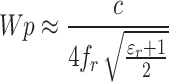 |
1 |
Fig. 3.

Single element design evolution in different steps.
Here The symbol c represents the speed of light in open area, and εr is the substrate’s relative permittivity.
Figure 4 depicted the corresponding S11 of every step at (a) sub-6 GHz band, (b) Ku-band, (c) mm-wave band. The original antenna was split into multiple slotted sections in order to obtain the bandwidth in the sub-6 GHz band, Ku-band, and frequency range in mm-wave bands. In step 2, a slot is cut in the middle of the patch, and in step 3, another slot is cut on the left arm of the patch to expand the bandwidth and reflection coefficient at the lower frequency band. But at step 3, some portion of the reflection coefficient at 4 GHz shifted to − 9 dB. Another slot is cut into the patch near the transmission line in step 4 for achieving the desired Ku-band and mm-wave band. In step 4, the lower frequency band remains the same as step 3. Before step 4, there was no -10-dB bandwidth at Ku-band and upper frequency band. But the bandwidth is not enough to cover the IoT applications at the upper frequency band. After adding a squire shaped parasitic element near the transmission line as like as step 5, at lower frequency band, the total bandwidth is achieved from 2.2 to 6.4 GHz. Moreover, the bandwidth is also increased at the Ku-band and mm-wave band in step 5. However, at mm-wave 28 GHz was not covered in step 5, and the bandwidth is increased at the Ku-band but not desired. The square-shaped parasitic element is designed to enhance impedance matching, which significantly improves both bandwidth and return loss across the entire frequency band. This optimization leads to better overall performance in terms of signal efficiency and quality. At step 6 and step 7, one triangular and another circular parasitic element is added at the back of the antenna, respectively. The triangular parasitic element increases the bandwidth in all proposed bands, and the final shape with the circular parasitic element achieved the desired bandwidth in all proposed bands (sub-6 GHz band, Ku-band, and mm-wave band). As seen in Fig. 4, at the final step (step 7), the proposed antenna achieved a bandwidth in sub-6 GHz band from 2 to 7 GHz, covering almost all important IoT applications and 5G sub-6 GHz applications. Alongside, the antenna has achieved an integrated coverage with Ku-band (13–17.45 GHz) and 5G mm-wave (24.5–38.2 GHz) applications.
Fig. 4.

Reflection Coefficient at (a) sub-6 GHz band, (b) Ku-band and (c) mm-wave band in different steps for IoT applications.
The impact of parasitic elements (at the back of the antenna) on the realized gain of a single-element antenna is demonstrated in Fig. 5. There is one triangular and one circular parasitic element is created to increase the realized gain of the single element antenna. Initially, at step 5, where no parasitic elements are present, the realized gain is lower, particularly in the sub-6 GHz band, where some frequencies even show negative gain, as illustrated in Fig. 5a. The maximum realized gain without any parasitic elements is 1.1 dBi. However, at step 6, with the introduction of a triangular-shaped parasitic element, the maximum realized gain improves to 3 dBi. Further enhancement is observed at step 7, where both triangular and circular-shaped parasitic elements are employed, resulting in a maximum realized gain of 3.8 dBi. A similar improvement is noted in the Ku-band, where the realized gain increases from 3.9 dBi (without parasitic elements at step 5) to 5.5 dBi when parasitic elements are added, as shown in Fig. 5b. In the millimeter-wave band, the parasitic elements play an even more significant role. At step 7, the realized gain increases to 8.5 dBi, compared to 5 dBi without parasitic elements at step 5, as shown in Fig. 5c. This clearly indicates that parasitic elements substantially enhance the realized gain of the antenna across multiple frequency bands, making them an effective design consideration for improving antenna performance.
Fig. 5.

Effect of parasitic element on realized gain (a) Sub-6 GHz band, (b) Ku-band, and (c) mm-wave band.
Figure 6 illustrates the equivalent circuit of the single-element antenna, providing an overview of its operational mechanism. The antenna operates across two distinct frequency regions: the microwave region, covering the sub-6 GHz and Ku-bands, and the millimeter-wave region. Achieving resonance across all these bands within a single equivalent circuit is challenging. While the proposed equivalent circuit successfully covers almost the full bandwidth, it does not capture all the peak resonances observed in the actual antenna performance. The design of the equivalent circuit for the single port antenna is started from the feedline. The feedline is modeled using the components R1, L1, and C1. A square-shaped parasitic element located near the feedline is represented by L4 and C4, while the gap between this parasitic element and the feedline is denoted by the capacitor C2. At the end of the feedline, there is a rectangular slotted patch, which creates four distinct sections of the patch. Each section is characterized by an LC component, where L9 and C14 correspond to the first part, L12 and C17 to the second part, and L10, C15, along with L11, C16, represent the third and fourth parts, respectively. Additionally, two arms are connected to this slotted patch. The first arm is modeled using C5, L4, while the second arm is represented by L3 and C4. The gap between the two arms is denoted by C19. Another parasitic element is connected to the first arm, represented by L5 and C7, with the gap between this parasitic element and the first arm represented by C6. The ground plane of the antenna is characterized by the components L15 and C22, which serve as the ground for the antenna system. The gap between the ground plane and the feedline is denoted by C26. Furthermore, two parasitic elements are located near the ground plane: a triangular parasitic element represented by C21 and L14, and a circular parasitic element denoted by C20 and L13. The gap between the ground and the triangular parasitic element is denoted by C25, while the gap between the triangular and circular parasitic elements is represented by C24. These parasitic elements play a crucial role in enhancing the antenna’s gain and achieving better impedance matching. In terms of frequency bands, the antenna’s sub-6 GHz band primarily resonates in the upper portion of the two arms. The Ku-band is primarily associated with the rectangular slotted patch, though the arms also contribute to the resonance in this band. The mm-wave band is mainly resonant due to the slotted patch, although each component of the antenna contributes to achieving an optimal reflection coefficient across all frequency bands. Figure 7 compares the reflection coefficients of the equivalent circuit and the antenna for (a) the sub-6 GHz band, (b) the Ku-band, and (c) the mm-wave band. The equivalent circuit was simulated using Advanced Design System (ADS) software. In the sub-6 GHz band, the CST simulation tool shows three resonance peaks, while ADS simulation reveals two. For the Ku-band, both simulation tools show two resonances with excellent reflection coefficient alignment. In the mm-wave band, CST simulation shows three resonance peaks, but ADS simulation reveals two. However, despite these differences, both CST and ADS simulations yield nearly identical operating bands for all frequency ranges.
Fig. 6.

Equivalent circuit of the single port antenna.
Fig. 7.

Reflection coefficient of single port antenna (CST vs ADS) (a) Sub-6 GHz band, (b) Ku-band, and (c) mm-wave band.
Results analysis of the single port antenna
The flow of surface current at various frequency domain is seen in Fig. 8. At 2.4 GHz, the current is primarily dispersed at the second arm, with some current passing via the feed line to the first arm. Similarly, at 3.5, the arms radiate a lot. On the other hand, 14.5 GHz in the Ku-band is being considered for the distribution of surface current. Evidently, the current is spread in intervals via the hole patch. The distribution of surface current for mm-wave at a frequency of 28 GHz is shown, with the largest current dispersed in the third slot and the circular reflector having some current only in the upper frequency band.
Fig. 8.

Single element surface current distribution at various frequencies.
The simulated and measured reflection coefficient (S11) of the proposed single element is presented in Fig. 9 at (a) sub-6 GHz band, (b) Ku-band, and (c) mm-wave band. The configuration has a prominent -10 dB bandwidth for all bands. The proposed single-element antenna has covered 2–7 GHz at the Sub-6 GHz band with a bandwidth percentage of 111.11%. At Ku-band, it has covered from 13 to 17.5 GHz in percentage 29.5%. At the same time, it has a percentage bandwidth of 43.71% (24.5–38.2 GHz) at the mm-wave band. According to the frequency band coverage analysis, the suggested single component configuration covers a lot of applications. For example, the sub-6 GHz band has covered the 4th generation LTE band with 2.5 GHz, ISM band with 2.4 GHz, WLAN band with 2.5 GHz and 5.5 GHz, 5G sub-6 GHz band with 3.5 GHz, 3.7 GHz, and 4.7 GHz, Vehicle to Everything communication band with 5.9 GHz. The proposed antenna also covered the Ku-band VSAT applications with the uplink band and for Broadcast Satellite Service (BSS). Moreover, it has coverage in mm-wave 5G communication systems with a frequency range of 24.5 GHz to 38.2 GHz. However, there has been some deviation in between simulated and measured results due to the measurement and fabrication error.
Fig. 9.

Reflection coefficient of single element at (a) sub-6 GHz band, (b) Ku-band, and (c) mm-wave band.
The realized gain and efficiency of the suggested single element are presented in Fig. 10 both simulated and measured. Maximum realized gain at the sub-6 GHz band is achieved with 3.8 dBi. At a lower band, for example, at 2.4 GHz, the realized gain is comparatively lower than the upper-frequency band. At 2 GHz gain is almost 1.6 dBi, and it is increased gradually at the upper-frequency band as shown in Fig. 7a. At the Ku-band, the realized maximum gain is 5.5 dBi, and the gain is stable at more than 5 dBi for the whole coverage band as shown in Fig. 7b. At the same time, as shown Fig. 7c, the gain at mm-wave frequency band is 8.5 dBi and most used 28 GHz frequency band has a realized gain of 7.5 dBi. The gain goes up as the frequency goes up because the effective size of the antenna increases at higher frequencies. Radiation efficiency is more than 80% at Ku-band and mm-wave frequency band while the efficiency fluctuates at sub-6 GHz band within 70–80%.
Fig. 10.

Realized gain and efficiency of single element at (a) sub-6 GHz band, (b) Ku-band, and (c) mm-wave band.
6-port 3D MIMO antenna development and design methodology
For 5G IoT communications, multiplex multiple-antenna systems with minimal mutual coupling and pattern variety are essential. Thus, as illustrated in Fig. 11, a 2-port antenna is initially created from a single port antenna. The size of each antenna is 35 × 35 mm2. Whereas the total dimension is 70 × 70 mm2. Rogers RT 5880 substrate is used for developing this antenna with a dielectric constant of 2.2 and a loss tangent value is 0.0009. The thickness of the substrate is 1.6 mm. Three units of 2-port antenna are developed and fabricated. A 3 × 2 MIMO antenna is crafted from a 2-port antenna by rotating it once along the x-axis and once along the y-axis, resulting in this innovative design as shown in Fig. 12. This permits the suggested 3 × 2 MIMO antenna system, represented in Fig. 13, to be formed by arranging six antenna pieces in a 3D configuration. And it also represents the fabricated prototype of the proposed 3D MIMO antenna.
Fig. 11.

2-port antenna Schematic design and fabricated prototype.
Fig. 12.

Three-unit 2-port antenna part assembling for final configuration of 3D 6-port 3 × 2 MIMO antenna.
Fig. 13.

Schematic model and fabricated prototype of the proposed 3 × 2 MIMO.
In this arrangement, each antenna appears at 90 degrees with the adjacent antenna. This arrangement increases MIMO antenna pattern variety in the E and H plane. The overall size of the six-port 3D 3 × 2 MIMO antenna is 70 × 70 × 70 mm3. Element-1 and element-4 are in the x-plane, element-2, element-5 in the y-plane, element-3, and element-6 are in the z-plane. Due to this configuration, the final structure of the antenna is very suitable for IoT communications.
Result analysis and discussion of 3D MIMO antenna
To verify the simulated outcomes, the MIMO antenna is manufactured. A 2.4 mm End Launch Jack for 0.062" BOARD DIA 0.012" PIN (MODEL NUMBER- 147–0701-241) is used for feeding the antenna. This jack can measure 0–50 GHz frequency. Figure 14a displays the measurement setup in a VNA and Fig. 14b in an anechoic chamber. The antenna is evaluated at the Electromagnetic Laboratory, Universiti Kebangsaan Malaysia, using a far-field measurement facility (anechoic chamber). Vector Network Analyzer (VNA) is used to evaluate the s-parameter. The simulated results are in excellent alignment with the experimental data.
Fig. 14.

Measurement setup of the suggested 3 × 2 MIMO arrangement (a) VNA (b) Anechoic Chamber.
Figure 15 illustrates the simulated and measured reflection coefficient of the suggested 6-port 3D MIMO antenna for (a) Sub-6 GHz band, (b) Ku-band and (c) mm-wave band. For the reflection coefficient, only S11 (port 1) is presented due to the identical behavior of all antenna components. It can be seen that in 3D 6-port 3 × 2 MIMO antenna, the reflection coefficient of lower frequency band and upper frequency band is almost similar to single element. The maximum return loss of -50 dB is achieved at 4.9 GHz for sub-6 GHz band. At Ku-band the maximum return loss is − 18 dB. Whereas at millimeter-wave band it is − 55 dB. However, there is some bandwidth increment depicted in the Ku-band.
Fig. 15.

Reflection Coefficient of the suggested 3 × 2 MIMO configuration at (a) Sub-6 GHz band, (b) Ku-band, and (c) mm-wave band.
The transmission coefficient, commonly referred to as isolation, represents the level of mutual coupling between antenna elements in a MIMO system. Figure 16 illustrates the transmission coefficient (isolation) of the proposed 3D 6-port MIMO antenna. In MIMO systems, isolation is critical for ensuring that antennas can operate independently without causing interference to one another. A higher isolation value indicates lower mutual coupling, meaning less interference between antenna ports. The proposed 3D MIMO antenna achieves high isolation due to the large distance between the antenna ports, a result of its unique 3D configuration. As the distance between the antenna ports increases, the interaction between the electromagnetic fields of each antenna is reduced. This reduction in interaction minimizes the mutual coupling effect, where one antenna can induce currents in another, thereby causing interference. With increased separation, the overlap between radiation patterns decreases, improving the isolation performance. In the proposed design, isolation is frequency dependent. At the lower frequency band (sub-6 GHz), the isolation is − 21 dB, which is comparatively lower due to the physical dimensions of the antenna. However, as the frequency increases, the isolation improves significantly. At the Ku-band, the isolation exceeds − 25 dB, and at higher frequency bands, it surpasses − 30 dB. The maximum isolation is almost − 50 dB in all three bands. Overall, the high isolation achieved across all frequency bands makes the proposed antenna ideal for uninterrupted 5G IoT communication systems, minimizing mutual coupling and providing superior performance compared to current literature.
Fig. 16.

Transmission Coefficient (Isolation) of the proposed 3 × 2 MIMO configuration at (a) Sub-6 GHz band, (b) Ku-band, and (c) mm-wave band.
Figure 17 presents the simulated and measured realized gain and radiation efficiency of the suggested MIMO antenna at (a) Sub-6 GHz band, (b) Ku-band, and (c) mm-wave band. They are increased in MIMO configuration due to the increment of substrate size. For example, at sub-6 GHz band at a lower frequency of 2.4 GHz, the realized gain was 1.5 dBi, and it is increased to 2.3 dBi at MIMO configuration. The maximum gain is increased up to 4.3 dBi at the operating bandwidth. At the Ku-band, the maximum realized gain was 5.5 dBi for the single element, which is increased to 7.3 dBi for the 3 × 2 MIMO antenna. However, simultaneously the maximum realized gain is increased to almost 10 dBi at the upper frequency band and at 28 GHz, the realized gain is more than 9.4 dBi. The maximum realized gain was 8.5 dBi at mm-wave in a single element. Alongside, the radiation efficiency is also increased. At the final 3 × 2 MIMO configuration, the maximum radiation efficiency is 85% at 4.2 GHz, and for the whole band, the average radiation efficiency is 80% for sub-6 GHz band. At the Ku-band, the average radiation efficiency is 84% for the whole operating bandwidth. Moreover, at the mm-wave band, the average radiation efficiency is achieved by almost 90%. For a 5G IoT communication system, a high gain and high efficiency are required.
Fig. 17.

Realized gain and efficiency of the suggested 3 × 2 MIMO configuration (a) Sub-6 GHz band, (b) Ku-band, and (c) mm-wave band.
To realize the radiation characteristic, Fig. 18 depicted the 2D radiation in both experimental and simulation at 3.5 GHz for sub-6 GHz band (a, b, c), 14.5 GHz at the Ku-band (d, e, f), and 28 GHz at mm-wave band (g, h, i). Due to the unique arrangement of the MIMO configuration, all antennas have identical behavior except for the radiation pattern. We have analyzed the radiation pattern for port 1 and port 4 since they are in opposite directions at MIMO configuration. Radiation patterns are demonstrated in magnetic field at both E-plane (phi = 0-degree; xoz plane, phi = 90 degree; yoz plane) and H-plane (theta = 90 degree; xoy plane). Evidently, the radiation patterns are omnidirectional at xoz plane and xoy plane and bi-directional at xoz plane for 3.5 GHz. For 14.5 GHz at all planes, radiation is directed omnidirectionally, and at 28 GHz, at xoz plane, an omnidirectional radiation pattern is observed, but for yoz and xoy plane end-fire radiation is depicted due to the parasitic elements at the back of the single element antenna. Due to the pattern diversity of the MIMO configuration the multipath losses are reduced.
Fig. 18.

2D Radiation characteristics of the suggested MIMO configuration where, (a, b, c) denoted the 3.5 GHz at xz plane, yz plane, and xy plane, respectively, (d, e, f) denoted the 14.5 GHz, and (g, h, i) denoted the 28 GHz.
The pattern diversity of the MIMO configuration is depicted in Fig. 19 for ports 1, 2, 4, and 5 at 3.5 GHz. As shown, the antenna radiates at different angles in the (a) E-plane and (b) H-plane, demonstrating clear pattern diversity. Specifically, the radiation is directed towards 180 degrees at port 1, 90 degrees at port 2, 0 degrees at port 3, and 270 degrees at port 4. Similarly, the other ports also exhibit pattern diversity, further confirming the antenna’s ability to radiate in different directions, enhancing the overall performance of the MIMO system.
Fig. 19.

Pattern diversity of the suggested 3 × 2 MIMO configuration at 3.5 (a) E-plane and (b) H-plane.
It is possible to assess MIMO antenna performance and capabilities by utilizing diversity properties. Diversity properties of the suggested MIMO configuration is evaluated by measuring the diversity gain (DG) and envelope-correlation-coefficient (ECC)34,35. The ECC, an essential measure for evaluating the interconnection among radiation properties of various antennas, can be calculated utilizing the far-field radiation method36,37. ECC can be calculated using Eq. (2).
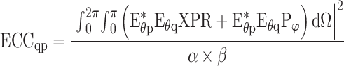 |
2 |
 and
and 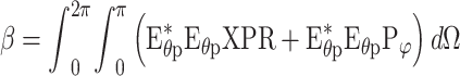
The optimal ECC value for a statistically insignificant MIMO antenna is zero38; however, for a realistic MIMO antenna, they advise preserving it at 0.5 for as long as feasible. For the suggested 3 × 2 MIMO arrangement, the measured and simulated ECC is < 0.004 at the sub-6 GHz band, Ku-band, and mm-wave band, as presented in Fig. 20. The obtained ECC indicates that the MIMO design performs well in terms of diversity.
Fig. 20.

Experimented and simulated ECC for the suggested 3 × 2 MIMO antenna at (a) Sub-6 GHz band, (b) Ku-band, and (c) mm-wave band.
An additional important metric for evaluating the effectiveness and potential of the MIMO structure is the Diversity Gain (DG). A MIMO system’s diversity performance is reduced by a factor of  because of antenna element correlation. Therefore, Eq. (3) can be used to find out the DG of a MIMO system with coupled nearby antenna components39.
 |
3 |
DG’s good region is at 10 dB. As seen in Fig. 21 for the (a) Sub-6 GHz band, (b) Ku-band, and (c) mm-wave bands, the recommended antenna maintains a consistent DG of almost 10 dB over its whole utilizable frequency spectrum.
Fig. 21.

Experimented and simulated DG for the suggested 3 × 2 MIMO antenna at (a) Sub-6 GHz band, (b) Ku-band, and (c) mm-wave band.
The Channel Capacity Loss (CCL) is a vital metric for evaluating MIMO antenna efficiency. As the number of antenna elements increases, so does channel capacity, but correlation between MIMO channels introduces capacity losses. CCL quantifies this impact on MIMO channel capacity and can be calculated using Eq. (4).40
 |
4 |
Here,  represent the port correlation matrix at the receiver. The CCL standard recommends achieving a value below 0.5 bps/Hz. Figure 22 shows the CCL for the proposed antenna for Sub-6 GHZ band, Ku-band, and mm-wave band both measured and simulated. Typically, a CCL of under 0.4 bps/Hz is desirable. In both simulations and experimental results, the proposed antenna maintains a CCL of less than 0.2 bps/Hz across the entire operating band.
Fig. 22.

Simulated and measured CCL of the proposed 3 × 2 MIMO antenna at (a) Sub-6 GHz band, (b) Ku-band, and (c) mm-wave band.
The Total Active Reflection Coefficient (TARC) is used to quantify the performance of multi-port antennas like MIMO antennas. For a 6-port MIMO antenna system, the TARC can be calculated using the following Eq. (5).40
 |
5 |
The TARC evaluates the performance of all six ports simultaneously, taking into account the interaction between them. For optimal performance, a low TARC value (close to 0) is desirable, indicating minimal reflection and good matching across all ports. As presented in Fig. 23, the proposed antenna has TARC less the -10 dB at Sub-6 GHZ band, Ku-band, and mm-wave band.
Fig. 23.

Simulated and measured TARC of the proposed 3 × 2 MIMO antenna at (a) Sub-6 GHz band, (b) Ku-band, and (c) mm-wave band.
3D radiation pattern for V2X application scenario
Intelligent Transportation Systems (ITS) have advanced thanks to developments in wireless communication technology, improving security and safety for both drivers and pedestrians. As a result, Vehicle-to-Everything (V2X) communication is now included in ITS41. There are many different types of interactions that cars can have with other things. Some of them include V2V, V2P, V2I, and V2X. The microwave or sub-6 GHz range (2.5 GHz to 5.9 GHz) is important in the V2X domain. Utilizing frequencies like 3.5 GHz in the microwave range and 28 GHz in the mm-wave spectrum allows vehicles to establish communication with a 5G cellular network and pedestrians. The V2P transmission facilitates communication between vehicles and Vulnerable Road Users. Meanwhile, contact with roadside infrastructure takes place using certain frequency bands, including ISM band, WLAN band, and Bluetooth band. The transmission of V2I application information is accomplished using either a Remote Switching Unit (RSU) or a locally accessible application server41,42.
This research presents a new six-port Multiple Input Multiple Output (MIMO) arrangement tailored for fifth generation IoT scenarios, integrating Vehicle-to-Everything (V2X) communication. The effectiveness of this MIMO antenna is assessed on a simulated car model through comprehensive simulations conducted with CST simulation software. It has been positioned on the roof of the automobile at a precisely designed distance of 6–10 mm in order to effectively separate the car from the antenna. By doing multiple simulations in an iterative manner, the most effective distance for separation is found to be 8.94 mm, demonstrating the efficiency of the suggested arrangement. Figure 24 depicts the 3D radiation pattern for all six ports and the simulated environment of the suggested antenna at 5.9 GHz. The radiation pattern observed is almost omnidirectional due to the antenna’s partial ground characteristic. The incorporation of six antennas in the MIMO antenna module, with each antenna positioned in a unique orientation, guarantees complete coverage of 360 degrees in both the horizontal and vertical planes. This setup enables smooth and continuous V2X communication, confirming the effectiveness of the suggested six-port MIMO orientation for fifth generation IoT applications in vehicle contexts.
Fig. 24.

3D Radiation pattern variety of the proposed MIMO antenna on an automobile for 6-port.
Realized gain verification based on machine learning (ML) technique
ML methodology
In recent years, there has been significant research and application of machine learning (ML) approaches in antenna design. These methods have been used to take advantage of their capability to acquire insights from simulated antenna data via training procedures43,44. Nevertheless, as a result of flaws in the manufacturing process, the recorded measurements may deviate from the anticipated results. The integration of machine learning (ML) into the design and validation process of antennas marks a significant advancement, particularly for researchers and students in economically disadvantaged regions. Traditionally, antenna design follows a sequence of simulation, prototype fabrication, and measurement. This approach, while reliable, is resource-intensive, often requiring multiple rounds of fabrication and testing to achieve the desired performance, such as gain, efficiency, or bandwidth. In some cases, the simulated antenna may demonstrate a high gain, the fabricated prototype could exhibit no gain, rendering the design ineffective. The high cost of materials, along with the sophisticated machinery required for fabrication, makes this process unsustainable for many. Machine learning offers a cost-effective solution by enhancing the reliability of simulations before fabrication, reducing the need for repeated prototype iterations. This study validates the achieved realized gain of the suggested single element antenna through the application of ML forecasting. A supervised regression ML strategy is used to accurately estimate the realized gain of the antenna.
The process of implementing machine learning consists of two primary stages. Initially, the process of data collecting takes place, which is then followed by training machine learning algorithms using the dataset in order to ascertain the most precise projection. Initially, a U-shaped patch structure is designed as the foundation of the antenna. Following this, extensive simulations are performed using parametric sweep45, aiming to collect the dimensions of various critical components, such as slots, stubs, the ground plane, the feedline, and parasitic elements. Each of these components plays a crucial role in shaping the antenna’s overall performance by influencing parameters like realized gain. To ensure accuracy, a systematic approach is adopted where the design variables are methodically altered, and the corresponding effects on antenna performance are observed through simulation iterations in CST Studio Suite. Once the simulations are completed, the key input variables such as dimension of slots, stubs, the ground plane, the feedline, and parasitic elements are extracted using the post-processing features available in CST. Meanwhile, the output data, such as gain, efficiency, and radiation patterns, are manually collected and analyzed. This collection of input–output data pairs serves as the foundation for constructing a dataset, which can later be used for further analysis or machine learning-based verification of the antenna realized gain. The effectiveness of ML regression methods can be improved by utilizing larger databases, depending on criteria such as the characteristics of the problem, the dimensions of the input parameters, and the accuracy levels of the method. A total of 210 data samples were obtained for the dataset through numerous simulations. During the 2nd stage, a range of regression algorithms are utilized to calculate the gain of the proposed antenna. The dataset generated contains numerical values, making supervised regression models ideal for training the predictive model. Three different supervised machine learning models—Random Forest Regression, Decision Tree Regression, and Gaussian Process Regression are employed due to their proven effectiveness in handling non-linear regression tasks. Antenna gain, for instance, often exhibits a non-linear relationship with input features such as antenna geometry. These models are adept at capturing such complex, non-linear patterns by averaging multiple predictions, thus improving accuracy. Additionally, they are particularly well-suited for smaller datasets, a common constraint in simulation-driven studies. The choice of these regression models is primarily driven by their ability to predict numerical outputs with high accuracy and their proven success in similar non-linear regression scenarios46. The structure depicted in Fig. 25, outlines the procedure of creating a dataset and executing an ML algorithm. The dataset is partitioned into two segments for distinct study, with all machines learning performed using Google Colab. The dataset is divided into two parts: 80% of the data (168 samples) is considered for training, while the rest of the 20% (42 samples) is reserved for testing, as per the recommended guidelines47. The training dataset is subsequently employed to train and cross-validate the machine learning model, allowing for precise prediction of key antenna performance metrics such as realized gain and efficiency. During the cross-validation process, the model is evaluated on various subsets of the data, which ensures robustness and mitigates overfitting. The testing dataset is then used to assess the model’s predictive capabilities, verifying its accuracy in estimating performance metrics. This method utilizes machine learning to reliably validate antenna parameters, including gain and efficiency, by minimizing errors and ensuring measurable accuracy. Predictive performance is assessed by comparing the model’s predictions with simulated outcomes, providing error rates and accuracy percentages. This data-driven approach enhances the reliability of antenna result validation, offering a structured mechanism to quantify discrepancies and improve precision. By leveraging data insights, this method ensures a more robust and accurate evaluation of antenna parameters based on error and accuracy, aligning predictions closely with simulation results.
Fig. 25.

Methodology flowchart of ML verification process.
ML models and performance metrics selection
Random Forest Regression48 is a machine learning algorithm that utilizes an ensemble of decision trees for predictive modeling.
Decision tree regression49 includes training a model to adhere to the hierarchical structure of a decision tree, where the qualities of an item are evaluated. This model is employed in a continuous manner to forecast forthcoming data and provide significant outcomes.
The use of ground-penetration radar (GPR) provides various advantages, including the ability to get precise results even with insufficient data and the ability to provide uncertainty estimates for forecasts50.
The error accuracy rate is the main statistical measure in regression analysis. This study conducted a comparative analysis of different machine learning algorithms, employing a wide range of analytical criteria to evaluate their respective results. The evaluation of prediction accuracy involved the use of metrics such as the coefficient of determination (R2) and the variance score. R-squared and variance score are suitable for antenna gain prediction because they measure how well the predicted values match the actual data, providing insights into the model’s overall accuracy. Both metrics quantify the proportion of variance explained, making them ideal for assessing prediction reliability in communication system performance. In the context of antenna gain prediction, selecting an appropriate error metric is crucial to accurately assess the performance of predictive models. Mean Squared Error (MSE), Mean Absolute Error (MAE), and Mean Squared Logarithmic Error (MSLE) each offer unique advantages for evaluating how well a model predicts antenna gain. MSE helps minimize significant prediction errors in antenna gain, MAE provides a balanced and interpretable measure of average prediction accuracy, and MSLE focuses on proportional errors, making it ideal for gain predictions across a wide range of values.
MSE is an evaluator of the average squared difference between forecasted and real values in a dataset51,52. Equation (6) is the formal expression of MSE as defined in reference.
 |
6 |
MAE is a standard that quantifies the average discrepancy among the observed and predicted values. The equation for MAE is given by Eq. (7) as described in reference53.
 |
7 |
where n = number of errors  = error absolute.
MSLE is conceptualized as a comparison between the observed and expected values. Equation (8) exhibits the Mean Squared Logarithmic Error (MSLE)54.
 |
8 |
An analytical benchmark known as the R-squared reveals how much of the dependent variable’s variance can be explained by the variables that are independent in the framework of regression. Equation (9) represents the mathematical expression for R-squared, as referenced by55.
 |
9 |
The explained variance score of each dataset quantifies the extent to which faults are spread out40. The computational interpretation is given by Eq. (10).
 |
10 |
Performance analysis and discussion of ML verification
Table 1 provides a detailed comparison of three regression methodologies: Random Forest Regression (RFR), Decision Tree Regression (DTR), and Gaussian Process Regression (GPR), evaluated across different performance metrics for error and accuracy. These models are employed to predict the realized gain of individual components in the sub-6 GHz, Ku-band, and mm-wave frequency ranges. Figure 26 further illustrates the comparison with a bar chart highlighting the precision of these models for (a) Sub-6 GHz band, (b) Ku-band, and (c) mm-wave band. Among the models, Random Forest Regression (RFR) is identified as the most optimal for determining the realized gain, particularly across the sub-6 GHz, Ku-band, and mm-wave bands. When evaluated using the Mean Absolute Error (MAE) metric, the RFR model achieves an error rate of 8% in the sub-6 GHz band, 3% in the Ku-band, and 10% in the mm-wave band. This demonstrates its robustness across different frequency ranges. In comparison, Gaussian Process Regression (GPR) displays a higher error rate, particularly in the mm-wave region, with a maximum error of 14%. This can be attributed to the limited quantity of data samples available in this frequency range, which negatively affects the GPR model’s performance. As a result, future work will prioritize increasing the dataset size to improve model accuracy and reduce errors, particularly for GPR. The selection of the optimal regression model was based on a comprehensive evaluation of both error and accuracy metrics. RFR consistently exhibited high precision, with R-squared (R2) and variance scores exceeding 97% in both the sub-6 GHz and Ku-bands. Furthermore, the RFR model achieved an accuracy rate of over 89% in the mm-wave band, despite the smaller dataset. This makes RFR the most reliable model for predicting antenna gain in various frequency ranges. Even though GPR and DTR models performed well, all models demonstrated accuracy levels above 85%, which is significant in validating the predicted realized gain against simulated data. This high level of accuracy suggests that the predicted results generated by all models align closely with the actual performance of the antennas. Finally, Fig. 27 presents a comparison between the simulated and predicted improvements for the RFR model using 42 test samples. The negligible discrepancies between the predicted and simulated results confirm the high accuracy of the RFR model in predicting antenna realized gain. In conclusion, the RFR model proves to be the best method for validating the realized antenna gain due to its lower error rates and superior accuracy across various frequency bands. To realize the characteristics of other models, we explored CNN, MLP, and MLMM for our dataset but achieved unsatisfactory results, particularly with CNN, which performed poorly due to the dataset’s limited size and numerical nature. CNNs typically excel with large datasets involving image, video, spatial, or time-series data. The accuracy was below 65.1% with an error rate exceeding 15.12% (Ku-band), 16.92% (Sub-6 GHz band), and 24.9% (mm-wave band). While MLPs can learn complex nonlinear relationships, they also require larger datasets for optimal performance. MLMMs, designed for heterogeneous or multimodal data, were not applicable here. Ultimately, we opted for supervised regression models to predict antenna results, as they were better suited to our dataset’s characteristics.
Table 1.
Error and accuracy analysis of the selected regression model for realized gain.
| Bands | Models | MAE (%) | MSE (%) | MSLE (%) | R2 (%) | Var Score (%) |
|---|---|---|---|---|---|---|
| Sub-6 GHz band | RFR | 7 | 2 | 0.1 | 97.4 | 97.3 |
| DTR | 8 | 3 | 0.3 | 96 | 96 | |
| GPR | 8 | 2 | 0.2 | 96.7 | 96.8 | |
| Ku-band | RFR | 3 | 0.3 | 0.01 | 97.3 | 97.4 |
| DTR | 3 | 0.4 | 0.01 | 97.1 | 97.2 | |
| GPR | 6 | 0.8 | 0.02 | 94.4 | 94.4 | |
| Mm-wave band | RFR | 10 | 3 | 0.04 | 89.4 | 89.6 |
| DTR | 11 | 4 | 0.05 | 86.8 | 87 | |
| GPR | 14 | 4 | 0.6 | 85.9 | 86 |
Fig. 26.

Bar chart of model accuracy at (a) Sub-6 GHz band, (b) Ku-band, and (c) mm-wave band.
Fig. 27.

Simulated vs predicted realized gain using Random Forest Regression.
Discussion and performance comparison analysis
The performance of the proposed 3 × 2 MIMO antenna is compared with existing literature in Table 2. Notably, none of the antennas discussed operate in the Ku-band, except for the one presented in1. In1, the authors developed a tri-band MIMO antenna system featuring a unique ‘S’-shaped design, covering the sub-6 GHz, Ku-band, and mm-wave frequencies. An innovative decoupling structure was employed to achieve isolation exceeding 20 dB, while maintaining a high efficiency of 90% across all bands with a fixed beam configuration. Despite these advancements, the realized gain of the antenna remains relatively low, indicating a trade-off in performance. This design demonstrates a balance between isolation, efficiency, and multi-band operation, with room for gain enhancement. In another study18, the authors employed a resonant cavity technique to achieve resonance in both the sub-6 GHz and mm-wave bands. This antenna offers 45-degree coverage in both theta and phi directions but exhibits low realized gain and efficiency. Additionally, its isolation performance is subpar compared to other MIMO antennas, highlighting limitations in its design and effectiveness for achieving optimal performance in demanding applications requiring higher gain, efficiency, and isolation. Many antennas, including those in18,20,21,56,57, utilize multiple ports to accommodate multiple integrated bands. However, works such as1,24,58 demonstrate the ability to cover both sub-6 GHz and mm-wave bands using a single feedline. Most of the antennas, except those in18,24, provide fixed beam coverage in the sub-6 GHz range. Among these, only24 offers 360-degree coverage in the theta direction across both sub-6 GHz and mm-wave bands, albeit with a lower realized gain than the proposed antenna. Isolation is critical in MIMO networks, and this comparison focuses on isolation at the sub-6 GHz band since all antennas exhibit strong isolation at mm-wave frequencies. Most antennas exhibit isolation ranging from 11 to 21 dB, except56, which achieves high isolation using a parasitic decoupling structure at the back of the MIMO antenna. Although56 achieves high efficiency, its realized gain is significantly lower than that of other current designs. The authors of58 employed a substrate-integrated waveguide (SIW) structure to achieve resonance in both the sub-6 GHz and mm-wave bands, with a gain of 4.35 dBi at sub-6 GHz, though the isolation at mm-wave frequencies is low, and the design is complex. In57, a shared aperture technique was utilized to cover the sub-6 GHz and mm-wave bands, resulting in a larger antenna size with higher realized gain. However, the antenna could not resonate in both bands from a single feedline. In59,60, the authors utilized self-decoupling techniques for isolation, but their antennas operate on a single band and exhibit low isolation, limiting their performance and broader applicability. The proposed 3D MIMO antenna offers a wide bandwidth, operates with a single feedline, and integrates coverage across the sub-6 GHz, Ku-band, and mm-wave frequencies. It achieves efficiency between 80 and 90% across all frequency ranges. In MIMO configuration, the antenna delivers a maximum gain of 4.3 dBi in the sub-6 GHz band, 5.5 dBi in the Ku-band, and nearly 10 dBi in the mm-wave band, with an isolation of 21 dB in the sub-6 GHz band and over 32 dB in other bands. Moreover, the antenna covers a full 360 degrees in both the theta and phi directions. The realized gain has also been verified through machine learning predictions in this work. Low realized gain and inadequate isolation are common challenges in MIMO antenna design. Metamaterials can offer promising solutions to these problems. Another key challenge is covering both microwave and mm-wave frequencies in a single design, which can be addressed by incorporating stubs with the patch. Additionally, for IoT applications, achieving 360-degree coverage in a MIMO system is crucial, which can be realized using 3D antenna design techniques.
Table 2.
The state of art comparison with the proposed work.
| References | 1 | 18 | 20 | 21 | 24 | 56 | 57 | 58 | 59 | 60 | Proposed | |
|---|---|---|---|---|---|---|---|---|---|---|---|---|
| Antenna type | Decoupling structure | Resonant cavity | Low pass filter | Tapered slot | SIW cavity | Parasitic decoupling technique | Shared Aperture | SIW structure | Self-decoupling | Self-decoupling | Patch + Parasitic | |
| Size (mm2) | 30 × 30 | 100 × 100 | 66 × 154 | 120 × 60 | 140 × 140 | 32 × 22 | 40 × 120 | 26 × 26 | 2 × 60 | 80 × 65 | 70 × 70 | |
| No of port | 4 | 2 | 4 | 4 | 2 | 2 | 6 | 4 | 2 | 2 | 6 | |
| Operating band (GHz) | Sub-6 | 5.2–5.7 | 3.45–3.58 | 3.5 | 3.6 | 3.46–3.72 | 2.4, 3.5, 5.3, 7.5 | 4.8, 6.29 | 2.4 | 3.4–3.6 | 1.46–1.52 | 2–7 |
| Ku | 11.8–17.3 | – | – | – | – | – | – | – | – | – | 13–17.5 | |
| mm-wave | 23.4–37.4 | 24.5–27 | 26 | 28 | 30–40 | 28 | 28 | 28 | – | – | 25–39 | |
| Efficiency (%) | 90 | 77.9 | 86.2 | – | 80 | 95 | 97 | 93 | 54–65 | 86.4–95.9 | 80–90 | |
| Realized Gain (dBi) [Sub-6/Ku/ mm-wave] | 3.05/5.27/6.97 | 4.85/–/5.48 | 3.8/–/7.5 | 3.5/–/8 | 3.9/–/7.5 | 5.32/–/6.2 | 7.6/–/15 | 4.35/–/8.5 | – | 4.7 | 4.3/5.5 /9.9 | |
| All band in single port? | Yes | No | No | No | Yes | No | No | Yes | Single band | Single band | Yes | |
| Beam coverage of the MIMO antennas | Sub-6 | Fixed beam |
45° (Theta) 45° (Phi) |
Fixed beam | Fixed beam | Fixed beam | Fixed beam | – | 360° (Theta) | Fixed beam | Fixed beam |
360° (Theta) 360° (Phi) |
| Ku | Fixed beam | – | – | – | – | – | – | – | – | – |
360° (Theta) 360° (Phi) |
|
| mm-wave | Fixed beam |
45° (Theta) 45° (Phi) |
60° (Theta) | Fixed beam | Fixed beam | Fixed beam | – | 360° (Theta) | – | – |
360° (Theta) 360° (Phi) |
|
| Isolation (dB) (at Sub-6) | 20 dB | 11 dB | 17 dB | – | 28 dB | – | 20 | 16.7 | 16.3 | 21 dB | ||
| ECC | < 0.007 | – | – | – | – | < 0.01 | – | < 0.001 | < 0.1 | < 0.02 | < 0.002 | |
| ML Verification | No | No | No | No | No | No | No | No | No | No | Yes | |
The proposed MIMO antenna demonstrates superior performance by offering 360-degree coverage in both horizontal and vertical planes, a feature absent in the compared designs. Additionally, it exhibits higher gain and wideband characteristics across three distinct frequency bands. Compared antennas are either larger in size or support fewer ports, underscoring the proposed antenna’s compactness and versatility. This compact design, combined with the ability to support multiple ports, makes it highly suitable for modern communication systems requiring high isolation and performance in constrained spaces. A unique aspect of this work is the integration of machine learning for validating the antenna’s realized gain, which is not present in the compared designs. However, the study is limited by the size of the machine learning dataset, which restricts the use of advanced algorithms like CNN. Future enhancements include further miniaturizing the antenna using the negative properties of metamaterials to achieve even greater efficiency and adaptability.
Conclusion
Nowadays, IoT devices are increasing significantly. According to Statista’s recent report, there will be 29 billion IoT-connected devices within 2030. Various frequency bands are used in various devices. Therefore, we need a single feed antenna which can be used in various IoT applications. For this reason, we have proposed an antenna which can cover 5G integrated Sub-6 GHz band and mm-wave band alongside the Ku-band for IoT applications. The proposed antenna can cover at Sub-6 GHz from 2 to 7 GHz, Ku-band bandwidth coverage from 13 to 17.5 GHz and mm-wave band from 25 to 39 GHz. In the scenario of IoT MIMO configuration, high isolation and high realized gain is the necessary thing. In the proposed antenna, we have developed a 6-port MIMO configuration with high isolation of 21 dB, 25 dB, and 30 dB at micro-wave, Ku-band, and mm-wave band, respectively. Moreover, the maximum realized gain achieved was more than 4 dBi at the Sub-6 GHz band, 5.5 dBi at the Ku-band, and almost 10 dBi at the mm-wave band, which is very prominent for IoT applications. This antenna’s most interesting and important feature is covered with a 360-degree beam pattern due to its unique MIMO configuration. The diversity performance of the MIMO arrangement shows excellent outcomes with a diversity gain (DG) of nearly 10 dB and an envelope correlation coefficient (ECC) value < 0.004 for all the achieved bands. Moreover, we have verified the single element realized gain based on machine learning prediction, and the predicted realized gain and simulated realized gain are nearly the same. The RFR model is the best model to predict the realized gain. Based on accuracy performance metrics, it is more than 97% in the RFR model, and in the error metrics, the maximum MAE is 7% at the mm-wave band due to the lower number of data samples. Due to the limited number of data samples, the CNN model does not work well with the proposed dataset. The proposed MIMO antenna has an area size of 70 × 70 mm2, which is prominently compact for IoT application-based devices, but it will be very impressive if we can reduce the size more. Our forthcoming research endeavors will prioritize the deployment of the proposed 3D MIMO antenna system within cutting-edge wireless indoor localization frameworks, striving to achieve uninterrupted 360-degree coverage. This pursuit will be underpinned by an in-depth evaluation of received signal strength to optimize system performance. Central objectives include the miniaturization of the antenna system and the augmentation of feeding ports to accommodate a broader array of IoT devices. Furthermore, we plan to significantly enhance the dataset volume to bolster machine learning applications, thereby improving system precision and operational efficiency. These initiatives aim to spearhead the advancement of innovative solutions for next-generation wireless communication technologies.
Acknowledgements
This research is funded by Researchers Supporting Project number (RSPD2024R992), King Saud University, Riyadh, Saudi Arabia.
Author contributions
Conception, design, data collection, analysis, and simulation were initially carried out by M.A.R. and S.S.A. All authors contributed to complete the writing and presentation of the whole manuscript.
Data availability
The datasets generated and/or analyzed during the current study are available from the corresponding author upon reasonable request.
Declarations
Competing interests
The authors declare no competing interests.
Ethical approval
Not Applicable.
Footnotes
Publisher’s note
Springer Nature remains neutral with regard to jurisdictional claims in published maps and institutional affiliations.
Contributor Information
Samir Salem Al-Bawri, Email: samir@ukm.edu.my, Email: s.albawri@gmail.com.
Noorlindawaty Md Jizat, Email: noorlindawaty.jizat@mmu.edu.my.
Mohammad Tariqul Islam, Email: tariqul@ukm.edu.my.
References
- 1.Ali, A. et al. Design process of a compact tri-band MIMO antenna with wideband characteristics for sub-6 GHz, Ku-band, and Millimeter-Wave applications. Ain Shams Eng. J.15, 102579. 10.1016/J.ASEJ.2023.102579 (2024). [Google Scholar]
- 2.Chettri, L. & Bera, R. A comprehensive survey on internet of things (IoT) toward 5G wireless systems. IEEE Internet Things J.7, 16–32. 10.1109/JIOT.2019.2948888 (2020). [Google Scholar]
- 3.Qian, Y., Wu, D., Bao, W. & Lorenz, P. The internet of things for smart cities: technologies and applications. IEEE Netw.33, 4–5. 10.1109/MNET.2019.8675165 (2019). [Google Scholar]
- 4.IoT connections worldwide 2022–2033, Statista, (n.d.). https://www.statista.com/statistics/1183457/iot-connected-devices-worldwide/ (accessed October 10, 2024).
- 5.Ranjan, P., Krishnan, A., Dwivedi, A. K., Singh, S. K. & Sharma, A. Design and optimization of MIMO dielectric resonator antenna using machine learning for Sub-6 GHz based on 5G IoT Applications. Arab. J. Sci. Eng.48, 14671–14679. 10.1007/S13369-023-07830-9/METRICS (2023). [Google Scholar]
- 6.Boukarkar, A., Rachdi, S., Mohamed Amine, M., Sami, B. & Benziane Khalil, A. A compact four states radiation-pattern reconfigurable monopole antenna for Sub-6 GHz IoT applications. AEU - Int. J. Electron. Commun.158, 154467. 10.1016/J.AEUE.2022.154467 (2023). [Google Scholar]
- 7.Karami, F., Boutayeb, H. & Talbi, L. Directive millimeter-wave end-fire diplexing antenna for IoT applications. IEEE Internet Things J.10, 19874–19882. 10.1109/JIOT.2023.3281748 (2023). [Google Scholar]
- 8.Bi, Y. et al. A millimeter-wave wideband antenna module with switchable fan-beam radiation for wide coverage of 5G IoT applications. IEEE Internet Things J.10, 20969–20983. 10.1109/JIOT.2023.3284848 (2023). [Google Scholar]
- 9.Al-Bawri, S. S., Islam, M. S., Sahaq, K. S. B., Marai, M. S., Jusoh, M., Sabapathy, T., Padmanathan, S., & Islam, M. T. Multilayer base station antenna at 3.5 GHz for future 5G indoor systems, in 2019 First International Conference of Intelligent Computing and Engineering (ICOICE), 1–4. 10.1109/ICOICE48418.2019.9035137 (2019).
- 10.Wang, Y., Zhang, J., Peng, F. & Wu, S. A glasses frame antenna for the applications in internet of things. IEEE Internet Things J.6, 8911–8918. 10.1109/JIOT.2019.2924236 (2019). [Google Scholar]
- 11.Occhiuzzi, C., Hughes, J. D., Venturi, F. R., Batchelor, J. & Marrocco, G. Folded comb-line array for backscattering-based bodycentric communications in the 5G Sub-6 GHz band. IEEE Trans. Antennas Propag.70, 6036–6041. 10.1109/TAP.2022.3161287 (2022). [Google Scholar]
- 12.Xiao, B., Wong, H., Wu, D. & Yeung, K. L. Design of small multiband full-screen smartwatch antenna for IoT applications. IEEE Internet Things J.8, 17724–17733. 10.1109/JIOT.2021.3082535 (2021). [Google Scholar]
- 13.Attia, H., Abdalrazik, A., Sharawi, M. S. & Kishk, A. A. Wideband circularly polarized millimeter-wave DRA array for internet of things. IEEE Internet Things J.10, 9597–9606. 10.1109/JIOT.2023.3235344 (2023). [Google Scholar]
- 14.Al-Alem, Y., Sifat, S. M., Antar, Y. M. M. & Kishk, A. A. Millimeter-wave planar antenna array augmented with a low-cost 3D printed dielectric polarizer for sensing and internet of things (IoT) applications. Sci. Reports10.1038/s41598-023-35707-2 (2023). [DOI] [PMC free article] [PubMed] [Google Scholar]
- 15.Cai, Z., Zhou, Y., Qi, Y., Zhuang, W. & Deng, L. A Millimeter wave dual-lens antenna for iot-based smart parking radar system. IEEE Internet Things J.8, 418–427. 10.1109/JIOT.2020.3004403 (2021). [Google Scholar]
- 16.Yang, J. et al. Quasi-deterministic modeling for industrial IoT channels based on millimeter wave measurements. IEEE Internet Things J.11, 8373–8385. 10.1109/JIOT.2023.3319048 (2024). [Google Scholar]
- 17.Liang, Q., Aliakbari, H. & Lau, B. K. Co-designed millimeter-wave and sub-6 GHz antenna for 5G smartphones. IEEE Antennas Wirel. Propag. Lett.21, 1995–1999. 10.1109/LAWP.2022.3187782 (2022). [Google Scholar]
- 18.Wen, L. et al. A dual-polarized aperture-sharing phased-array antenna for 5G (3.5, 26) GHz communication. IEEE Trans. Antennas Propag.71, 3785–3796. 10.1109/TAP.2023.3245183 (2023). [Google Scholar]
- 19.Ikram, M., Nguyen-Trong, N. & Abbosh, A. M. Common-aperture sub-6 GHz and millimeter-wave 5G antenna system. IEEE Access8, 199415–199423. 10.1109/ACCESS.2020.3034887 (2020). [Google Scholar]
- 20.Shamoon, S., Zhou, W. Y., Shahzad, F., Ali, W. & Subbyal, H. Integrated sub-6 GHz and millimeter wave band antenna array modules for 5G smartphone applications. AEU - Int. J. Electron. Commun.161, 154542. 10.1016/J.AEUE.2023.154542 (2023). [Google Scholar]
- 21.Hoang, M. T. & Ikram, M. 5G/B5G internet of things MIMO antenna design. Signals2022(3), 29–37. 10.3390/SIGNALS3010003 (2022). [Google Scholar]
- 22.Lan, J., Yu, Z., Zhou, J. & Hong, W. An aperture-sharing array for (3.5, 28) GHz terminals with steerable beam in millimeter-wave band. IEEE Trans. Antennas Propag.68, 4114–4119. 10.1109/TAP.2019.2948706 (2020). [Google Scholar]
- 23.Liu, Y., Li, Y., Ge, L., Wang, J. & Ai, B. A compact hepta-band mode-composite antenna for sub (6, 28, and 38) GHz applications. IEEE Trans. Antennas Propag.68, 2593–2602. 10.1109/TAP.2019.2955206 (2020). [Google Scholar]
- 24.Yang, X. et al. Joint microwave and millimeter-wave antenna design for UAV-enabled communications. IEEE Trans. Ind. Informatics19, 10739–10750. 10.1109/TII.2023.3241591 (2023). [Google Scholar]
- 25.Islam, S., Zada, M. & Yoo, H. Low-pass filter based integrated 5G smartphone antenna for sub-6-GHz and mm-wave bands. IEEE Trans. Antennas Propag.69, 5424–5436. 10.1109/TAP.2021.3061012 (2021). [Google Scholar]
- 26.Feng, B., Chen, J., Yin, S., Sim, C. Y. D. & Zhao, Z. A tri-polarized antenna with diverse radiation characteristics for 5G and V2X communications. IEEE Trans. Veh. Technol.69, 10115–10126. 10.1109/TVT.2020.3005959 (2020). [Google Scholar]
- 27.Mao, C. X., Gao, S. & Wang, Y. Dual-band full-duplex Tx/Rx antennas for vehicular communications. IEEE Trans. Veh. Technol.67, 4059–4070. 10.1109/TVT.2017.2789250 (2018). [Google Scholar]
- 28.Kaya, A.Ö., Calin, D., & Viswanathan, H. 28 GHz and 3.5 GHz wireless channels: Fading, delay and angular dispersion, in Proc. - IEEE Glob. Commun. Conf. GLOBECOM (2016).10.1109/GLOCOM.2016.7841484 (2016).
- 29.Rani, T., Das, S. C., Hossen, M. S., Paul, L. C. & Roy, T. K. Development of a broadband antenna for 5G sub-6 GHz cellular and IIoT smart automation applications, 12th Int. Conf. Electr. Comput. Eng. ICECE2022, 465–468. 10.1109/ICECE57408.2022.10088497 (2022). [Google Scholar]
- 30.Carkaci, M. E. & Secmen, M. Design and prototype manufacturing of a feed system for Ku-band satellite communication by using 3D FDM/PLA printing and conductive paint technology. Int. J. RF Microw. Comput. Eng.30, e22062. 10.1002/MMCE.22062 (2020). [Google Scholar]
- 31.Manshari, S., Koziel, S. & Leifsson, L. Compact dual-polarized corrugated horn antenna for satellite communications. IEEE Trans. Antennas Propag.68, 5122–5129. 10.1109/TAP.2020.2980337 (2020). [Google Scholar]
- 32.Rahman, M. A., Al-Bawri, S. S., Islam, M. T., Singh, M. J. & Rahman, M. A. A novel compact ultrawideband microstrip patch antenna for satellite communications system. Springer Proc. Phys.303, 243–251. 10.1007/978-981-97-0142-1_25 (2024). [Google Scholar]
- 33.Hossen, M. S. et al. DNG metamaterial-inspired slotted stub antenna with enhanced gain, efficiency and distributed current for early stage bone fracture detection applications. IEEE Sens. J.10.1109/JSEN.2024.3459794 (2024). [Google Scholar]
- 34.Shabbir, T., Saleem, R., Al-Bawri, S. S., Shafique, M. F. & Islam, M. T. Eight-port metamaterial loaded UWB-MIMO antenna system for 3D system-in-package applications. IEEE Access8, 106982–106992. 10.1109/ACCESS.2020.3000134 (2020). [Google Scholar]
- 35.Shabbir, T. et al. 16-Port non-planar mimo antenna system with near-zero-index (nzi) metamaterial decoupling structure for 5g applications. IEEE Access8, 157946–157958. 10.1109/ACCESS.2020.3020282 (2020). [Google Scholar]
- 36.Rahman, M. A., Al-Bawri, S. S., Abdulkawi, W. M. & Islam, M. T. Miniaturized tri-band integrated microwave and millimeter-wave MIMO antenna loaded with metamaterial for 5G IoT applications. Results Eng.24, 103130. 10.1016/J.RINENG.2024.103130 (2024). [Google Scholar]
- 37.Ullah, U., Al-Hasan, M., Koziel, S. & Ben Mabrouk, I. Circular polarization diversity implementation for correlation reduction in wideband low-cost multiple-Input-multiple-output antenna. IEEE Access8, 95585–95593. 10.1109/ACCESS.2020.2995723 (2020). [Google Scholar]
- 38.Urimubenshi, F., Konditi, D. B. O., de Dieu Iyakaremye, J., Moukala Mpele, P. & Munyaneza, A. A novel approach for low mutual coupling and ultra-compact Two Port MIMO antenna development for UWB wireless application. Heliyon10.1016/j.heliyon.2022.e09057 (2022). [DOI] [PMC free article] [PubMed] [Google Scholar]
- 39.Haque, M. A. et al. Broadband high gain performance MIMO antenna array for 5 G mm-wave applications-based gain prediction using machine learning approach. Alexandria Eng. J.104, 665–679. 10.1016/J.AEJ.2024.08.025 (2024). [Google Scholar]
- 40.Rahman, M. A., Al-Bawri, S. S., Abdulkawi, W. M., Aljaloud, K. & Islam, M. T. A unique SWB multi-slotted four-port highly isolated MIMO antenna loaded with metasurface for IOT applications-based machine learning verification. Eng. Sci. Technol. an Int. J.50, 101616. 10.1016/J.JESTCH.2024.101616 (2024). [Google Scholar]
- 41.Ikram, M., Sultan, K. S., Abbosh, A. M. & Nguyen-Trong, N. Sub-6 GHz and mm-wave 5G vehicle-to-everything (5G–V2X) MIMO antenna array. IEEE Access10, 49688–49695. 10.1109/ACCESS.2022.3172931 (2022). [Google Scholar]
- 42.Kawser, M. T., Fahad, M. S., Ahmed, S., Sajjad, S., & Rafi, H. A. The perspective of vehicle-to-everything (V2X) Communication towards 5G, (2019).
- 43.Haque, M. A. et al. Machine learning-based technique for resonance and directivity prediction of UMTS LTE band quasi Yagi antenna. Heliyon9, e19548. 10.1016/j.heliyon.2023.e19548 (2023). [DOI] [PMC free article] [PubMed] [Google Scholar]
- 44.Haque, M. A. et al. Quasi-Yagi antenna design for LTE applications and prediction of gain and directivity using machine learning approaches. Alexandria Eng. J.80, 383–396. 10.1016/J.AEJ.2023.08.059 (2023). [Google Scholar]
- 45.Haque, M. A., Zakariya, M. A., Singh, N. S. S., Rahman, M. A. & Paul, L. C. Parametric study of a dual-band quasi-Yagi antenna for LTE application. Bull. Electr. Eng. Inform.12, 1513–1522. 10.11591/EEI.V12I3.4639 (2023). [Google Scholar]
- 46.Talpur, M. A. H., Khahro, S. H., Ali, T. H., Bin Waseem, H. & Napiah, M. Computing travel impendences using trip generation regression model: a phenomenon of travel decision-making process of rural households. Environ. Dev. Sustain.25, 5973–5996. 10.1007/S10668-022-02288-5/METRICS (2023). [Google Scholar]
- 47.Nguyen, Q. H. et al. Influence of data splitting on performance of machine learning models in prediction of shear strength of soil. Math. Probl. Eng.2021, 4832864. 10.1155/2021/4832864 (2021). [Google Scholar]
- 48.Borup, D., Christensen, B. J., Mühlbach, N. S. & Nielsen, M. S. Targeting predictors in random forest regression. Int. J. Forecast.39, 841–868. 10.1016/J.IJFORECAST.2022.02.010 (2023). [Google Scholar]
- 49.Rakhra, M. et al. WITHDRAWN: Crop price prediction using random forest and decision tree regression:-A review. Mater. Today Proc.10.1016/J.MATPR.2021.03.261 (2021). [Google Scholar]
- 50.Olukanni, S. E., Risi, I., Salifu, F. U. & Oladipupo, S. A gaussian process regression model to predict path loss for an urban environment. Int. J. Math. Sci. Comput.9, 10–21. 10.5815/IJMSC.2023.02.02 (2023). [Google Scholar]
- 51.Haque, M. A. et al. Dual band antenna design and prediction of resonance frequency using machine learning approaches. Appl. Sci.2022(12), 10505. 10.3390/APP122010505 (2022). [Google Scholar]
- 52.Haque, M. A. et al. Machine learning-based technique for directivity prediction of a compact and highly efficient 4-port MIMO antenna for 5G millimeter wave applications. Results Eng.24, 103106. 10.1016/J.RINENG.2024.103106 (2024). [Google Scholar]
- 53.Harishkumar, K. S., Yogesh, K. M. & Gad, I. Forecasting air pollution particulate matter (PM2.5) using machine learning regression models. Procedia Comput. Sci.171, 2057–2066. 10.1016/J.PROCS.2020.04.221 (2020). [Google Scholar]
- 54.Haque, M. A. et al. Machine learning-based technique for gain and resonance prediction of mid band 5G Yagi antenna. Sci. Reports131, 1–22. 10.1038/s41598-023-39730-1 (2023). [DOI] [PMC free article] [PubMed] [Google Scholar]
- 55.Ashraful Haque, M. et al. Machine learning-based approach for bandwidth and frequency prediction for N77 band 5G antenna. Phys. Scr.99, 026005. 10.1088/1402-4896/AD1D40 (2024). [Google Scholar]
- 56.Ghosh, S., Baghel, G. S. & Swati, M. V. A dual-port, single-fed, integrated microwave and mm-wave MIMO antenna system with parasitic decoupling mechanism for 5G-enabled IoT applications. AEU - Int. J. Electron. Commun.176, 155122. 10.1016/J.AEUE.2024.155122 (2024). [Google Scholar]
- 57.Lin, Y., Zheng, S. & Liang, Z. Design of a microwave/millimeter-wave shared-aperture antenna by hybridizing series-fed antenna array and leaky wave antenna. IEEE Trans. Antennas Propag.72, 4764–4772. 10.1109/TAP.2024.3391904 (2024). [Google Scholar]
- 58.Aparna, E., Ram, G. & Kumar, G. A. 5G mm-wave technology: Innovative design of integrating mm-wave wideband antenna with a compact CP microwave antenna for diverse applications. IEEE Access12, 56633–56641. 10.1109/ACCESS.2024.3389501 (2024). [Google Scholar]
- 59.Fang, Y., Jia, Y., Zhu, J. Q., Liu, Y. & An, J. Self-decoupling, shared-aperture, eight-antenna MIMO array With MIMO-SAR reduction. IEEE Trans. Antennas Propag.72, 1905–1910. 10.1109/TAP.2023.3339223 (2024). [Google Scholar]
- 60.Sun, L., Li, Y., Zhang, Z. & Wang, H. Antenna decoupling by common and differential modes cancellation. IEEE Trans. Antennas Propag.69, 672–682. 10.1109/TAP.2020.3009427 (2021). [Google Scholar]
Associated Data
This section collects any data citations, data availability statements, or supplementary materials included in this article.
Data Availability Statement
The datasets generated and/or analyzed during the current study are available from the corresponding author upon reasonable request.