Abstract
This study investigates the impact of integrating g-C3N4 into CuCo2O4 electrodes on electrochemical performance working as binder-free electrodes. Flower-like CuCo2O4 nanostructures on nickel foam are decorated with few-layer g-C3N4 using a secondary hydrothermal process. The hierarchical g-C3N4/CuCo2O4 nanoflower electrode demonstrates a specific capacity of 247.5 mA h g−1 at a current density of 1 A g−1, while maintaining a capacity of 87.0 mA h g−1 at a heightened current density of 5 A g−1. Notably, this electrode exhibited remarkable durability, retaining 98% of its capacity after 1000 cycles. The g-C3N4/CuCo2O4 heterostructure shows promise for high-performance energy storage devices.
Flower-like g-C3N4/CuCo2O4 structures have been successfully established by decorating g-C3N4 on CuCo2O4 nanostructures, demonstrating excellent specific capacity and cyclic stability as a pseudocapacitance electrode.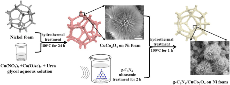
1. Introduction
The problems related to environmental pollution from fossil fuel energy sources, along with the swift rise in demand for portable electronic devices, have posed considerable challenges for energy storage materials. Consequently, researchers have been motivated to explore energy storage materials that provide higher power density, greater charge–discharge speed, and outstanding longevity.1,2 Electrochemical energy storage devices generally include rechargeable batteries and supercapacitors. In contrast to traditional batteries, which depend on chemical reactions for energy storage and release, supercapacitors operate based on a physical mechanism known as electric double-layer capacitance. One of the main advantages of supercapacitors lies in their affordability. The components and production techniques utilized in creating these devices are relatively simple, leading to lower manufacturing costs compared to batteries.3
Supercapacitors are appealing due to their cost-effectiveness, simplicity of manufacturing, impressive power density, high charge–discharge speed, and outstanding longevity. These features make them extremely well-suited for meeting the demands of modern portable gadgets, such as wearable technology.4 Energy storage in electric double-layer capacitors is limited to the interface of the electrode material, resulting in a constrained capacity. For instance, the use of activated carbon as electrodes results in a decrease in the discharging capacity of the carbon electrodes (70–250 F g−1).5 Nevertheless, faradaic capacitor materials offer advantages over electrochemical double-layer capacitors by not only storing electric double-layer energy but also maintaining charge through electron transfer at active electrode electrochemical sites during fast redox reactions.6,7 While serving as effective faradaic capacitor electrodes, bimetallic oxides with multiple oxidation states exhibit superior reversible capacity, structural durability, and electrical stability compared to single metal oxides. CuCo2O4, a bi-transition metal oxide that combines the advantageous properties of both copper and cobalt oxides, displays good electrical conductivity and excellent electrochemical activity. Despite these benefits, the practical application of CuCo2O4 in supercapacitors is still hindered by its limited surface area and inherent poor cycling stability. To date, many efforts have been devoted to the design of spinel CuCo2O4 electrodes with diverse morphologies such as nanobelts,8 nanograss,9 nanowires,10,11 and nanosheets.12,13 Moreover, several CuCo2O4-based nanocomposites have been explored through a variety of synthetic routes, such as CuCo2O4/CuO,14 CuCo2O4/MnCo2O4 heterostructures,15 CuCo2O4@CQDs,16 CuCo2S4/CuCo2O4,17,18 CuCo2O4@Co3O4,19 CuCo2O4@CuCo2S4@Co(OH)2,20 and CuCo2O4/rGO.21
g-C3N4 possesses a two-dimensional sheet structure and demonstrates exceptional performance in semiconductor applications, photocatalysis, environmental science, and other fields. This work presents a novel approach aimed at improving the electrochemical performance of CuCo2O4 nanoflowers on nickel foam through the coating of g-C3N4 nanosheets, generating synergistic effects between the bimetal oxide and the metal-free g-C3N4. The layered structure of g-C3N4 facilitates the surface area of the electrode, and the good chemical stability of g-C3N4 helps in improving cycling capacity retention. An asymmetrical supercapacitor is fabricated to demonstrate the application potential of the g-C3N4/CuCo2O4 nanocomposite. This work not only highlights the potential of g-C3N4 as an effective coating material for transition metal oxides but also provides valuable insights into the design of high-performance electrode materials for next-generation supercapacitors.
2. Materials and methods
2.1. Synthesis of nanoflower CuCo2O4 on nickel foam carrier
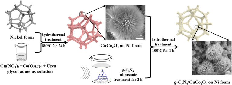
All chemicals were of reagent quality and used without any additional refinement. The nickel foam was cut to a size of 1 cm × 1 cm and then alternately washed with ultrasonic assistance with acetone, 3 M HCl, deionized water, and ethanol for 10 minutes each. Finally, the nickel foam was dried in vacuum at 50 °C for 10 hours, weighed, and stored. The synthetic route described in the following is shown in Fig. 1. The precursor solution for synthesizing CuCo2O4 was prepared by dissolving copper nitrate trihydrate (0.2416 mg), cobalt acetate tetrahydrate (0.4982 mg), and urea (0.3600 mg) in a solvent under continuous stirring until a uniform blue solution with a pH value of 5 was obtained. To control the morphology of CuCo2O4 nanostructure by adjusting the solubility and wetting effect, 10 mL of ethylene glycol and 20 mL of deionized water were mixed as a solvent. The cleaned nickel foam was then immersed in the precursor solution and transferred in a 50 mL PTFE-lined stainless-steel autoclave. The autoclave was sealed and heated at 120 °C in a blast drying oven for 12 hours to complete the reaction. After cooling down to room temperature, the CuCo2O4 electrode material on the nickel foam was obtained by rinsing with deionized water and drying at 60 °C in vacuum.
Fig. 1. Schematic diagram of the synthetic procedure.
2.2. Synthesis of nanoflower g-C3N4/CuCo2O4 on nickel foam
Nanoflower g-C3N4/CuCo2O4 was synthesized by coating few-layer g-C3N4 on the surface of CuCo2O4. The g-C3N4 powder was obtained by annealing urea in air at 550 °C for 2 hours. Then, 10 mg of g-C3N4 powder was added in 30 mL of deionized water in a 50 mL volumetric flask and dispersed ultrasonically for 1 hour. After sitting undisturbed for one day, a suspension with a g-C3N4 concentration of 0.116 g L−1 was obtained in the supernatant, indicating a production rate of ∼30%. Then, the as-prepared CuCo2O4-coated nickel foam was immersed in 20 mL of the g-C3N4 suspension, sealed in an air oven, and heated at 120 °C for 12 hours. To study the effect of g-C3N4 concentration on the electrochemical performance, each of 2, 5, 10, and 15 mL of g-C3N4 suspension was diluted with deionized water to 20 mL to repeat the above experiment. Finally, the nickel foam was rinsed with deionized water and dried at 60 °C to obtain nanoflower g-C3N4/CuCo2O4 on nickel foam.
2.3. Characterization
The morphologies and compositions of the samples were analyzed using a field-emission scanning electron microscope (FE-SEM, SUPRA 40, Zeiss, Germany) and a transmission electron microscope (TEM, Tecnai G20, FEI, USA). Surface compositions were examined through X-ray photoelectron spectroscopy (XPS, Escalab 250Xi, Thermo Fisher Scientific, USA). To avoid charging effect, all spectra were referenced to the C–C bond at 284.8 eV in the C 1s spectrum. The samples' crystallographic structure was analyzed using X-ray diffraction (XRD, D8-Discovery, Brucker, 40 kV, 15 mA, Cu Kα, λ = 1.5406 Å), while the functional groups in the samples were investigated through Fourier transform infrared (FTIR) spectroscopy (Nicolet-5700, Thermo Fisher, USA).
The electrochemical characteristics of the samples were examined using an electrochemical workstation (CHI 760E, CH Instruments, China) using a standard three-electrode electrochemical setup. g-C3N4/CuCo2O4 on nickel foam was utilized directly as the working electrode without using conductive agents or binders. A Hg/HgO electrode and a platinum plate served as the reference electrode and the counter electrode, respectively. All the electrochemical tests were conducted in a 6.0 mol L−1 KOH aqueous solution at ambient temperature. Various scan rates were employed for cyclic voltammetry (CV) tests, while galvanostatic charge–discharge (GCD) tests were conducted at different current densities. The specific capacitances (C) were determined from the GCD discharge curves by formula (1):
| C = I × Δt/(ΔV × m) | 1 |
where I represents the discharge current in amperes (A), t denotes the duration of discharge in seconds (s), ΔV indicates the voltage range in volts (V), and m refers to the mass of the active materials measured in grams (g).
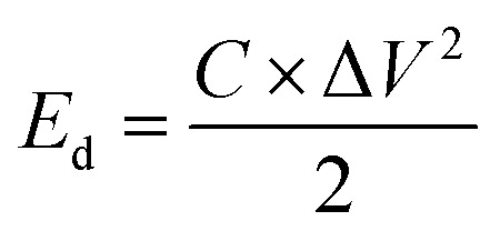
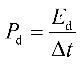
The calculation of the energy density and power density for the electrodes was performed using formulas (2) and (3):
 |
2 |
 |
3 |
In the equation for energy storage systems, the energy density, denoted as Ed and measured in watt-hours per kilogram (W h kg−1), plays a crucial role in determining the amount of energy that can be stored in a given mass of material. Specific capacitance, represented as C and expressed in farads per gram (F g−1), is another significant parameter that reflects the ability of a material to store electrical charge. Additionally, the potential range, indicated as ΔV and measured in volts (V), outlines the voltage limits within which the energy storage device operates effectively. Furthermore, power density, denoted as Pd and expressed in watts per kilogram (W kg−1), quantifies the rate at which energy can be delivered per unit mass. Lastly, the discharge time, denoted as Δt and measured in seconds (s), indicates the duration required for the device to release its stored energy.
Electrochemical impedance spectroscopy (EIS) was conducted under a measured open voltage as the initial voltage and an amplitude of 5 mV with frequency scanning from 0.01 Hz to 100 kHz.
3. Results and discussion
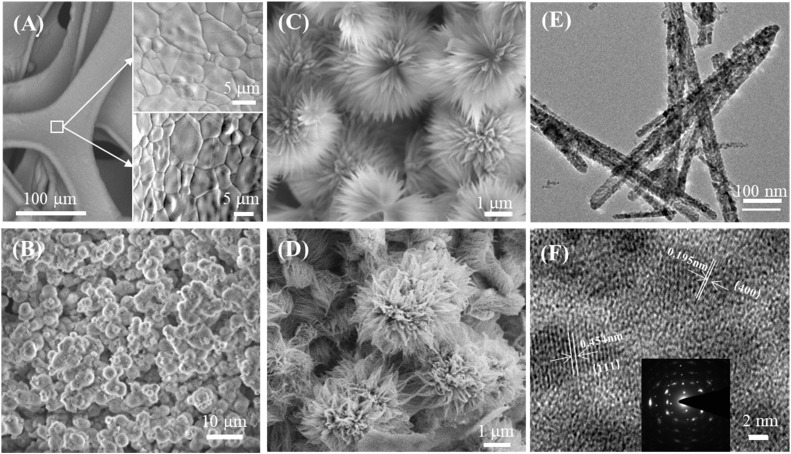
Although CuCo2O4 materials are commonly discussed in the literature, the innovative and intriguing nanoflower g-C3N4/CuCo2O4 binder-free electrode on three–dimensional nickel foam stands out. Fig. 2A presents SEM views of the surface structure of nickel foam before and after acid treatment. It can be seen that there are distinct grain boundaries in both images, while the surface of the nickel foam after acid treatment is rougher than that without acid treatment. Notably, the rough surface created by acid treatment is essential for the nucleation process of metal ions. When the ion concentration surpasses the threshold necessary for nucleation, the resulting concentration supersaturation leads to the continuous precipitation of CuCo2O4 crystal nuclei on the rough surface of the nickel foam, serving as existing defect sites. Fig. 2B is a SEM image of CuCo2O4-grown nickel foam, showing that the surface of the nickel foam is coated densely with flower-like CuCo2O4 nanostructures. As shown in Fig. 2C, the distinctive flower-like CuCo2O4 with a diameter of approximately 5 μm consists of nanopetals. Fig. 2D is an SEM image of the flower-like structure of g-C3N4/CuCo2O4, showing that the few g-C3N4 layers are clustered together at the tips of the petals. This structure, obtained through secondary hydrothermal treatment, is stable and firmly adhered to the pristine nickel foam. The TEM image presented in Fig. 2E illustrates the morphology of the nanopetals scraped from a CuCo2O4 flower. As shown in Fig. 2F, the lattice fringes with interplanar distances of 0.195 and 0.454 nm correspond to the (400) and (111) crystal planes of CuCo2O4, respectively.
Fig. 2. (A) SEM images of the nickel foam surface before and after acid treatment. (B) The CuCo2O4 nanoflower structure deposited on the nickel foam. (C) Magnified SEM image of CuCo2O4. (D) Magnified SEM image of g-C3N4/CuCo2O4. (E) TEM image of CuCo2O4 nanopetals. (F) HRTEM image of one CuCo2O4 nanopetal.
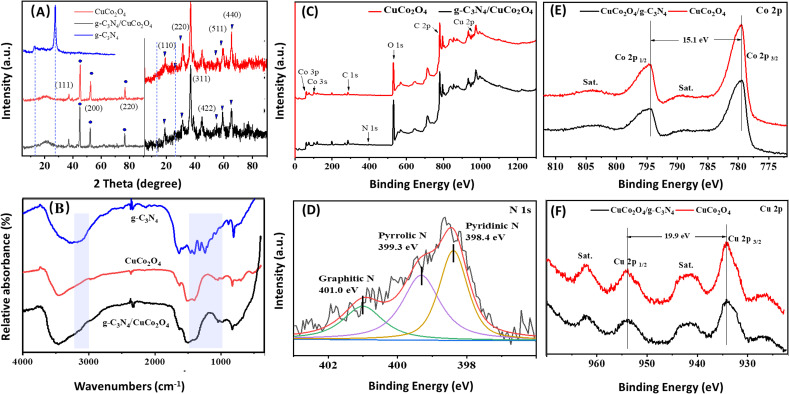
The phase structures of CuCo2O4 and g-C3N4/CuCo2O4 were analyzed using XRD. As shown in the left-hand panel of Fig. 3A, three sharp XRD peaks (indicated by “•”) are observed at 45.0°, 52.5°, and 76.8°, corresponding to the strong background of Ni (111), (200), and (220) planes originating from the nickel foam substrate. To observe the minor peaks more clearly, the y-axis is zoomed in to eliminate interference from background peaks, as shown in the right-hand panel of Fig. 3A. For the XRD patterns of both CuCo2O4 and g-C3N4/CuCo2O4, all the minor diffraction peaks can be definitively attributed to CuCo2O4 (JCPDS no. 37-0878). The identified diffraction peaks at 19.3°, 31.4°, 36.9°, 55.8°, 59.5°, and 65.3° (denoted by “▼”) can be categorized as the (111), (220), (311), (422), (333), and (440) planes, respectively. Pure g-C3N4 theoretically exhibits two prominent diffraction peaks at 13.2° and 27.4°, corresponding to the (100) and (002) peaks of the graphitic phase (JCPDS no. 87-1526).22 However, no distinct peak related to g-C3N4 is detectable in the XRD pattern of the g-C3N4/CuCo2O4 sample, possibly due to the lower content of g-C3N4.
Fig. 3. Spectral characterizations of the samples. (A) XRD patterns of CuCo2O4 and g-C3N4/CuCo2O4. (B) FTIR spectra of g-C3N4, CuCo2O4 and g-C3N4/CuCo2O4. (C) Survey XPS. (D) N 1s XPS of g-C3N4/CuCo2O4. (E) Co 2p and (F) Cu 2p XPS of CuCo2O4 and g-C3N4/CuCo2O4.
To confirm the presence of g-C3N4, FTIR spectra of pure g-C3N4, CuCo2O4, and g-C3N4/CuCo2O4 are illustrated in Fig. 3B. All samples exhibit vibrations corresponding to surface-adsorbed water (1644 and 3100 cm−1) and CO2 molecules (2380 cm−1). In the case of pure g-C3N4, the prominent peaks at 1248, 1325, 1408, 1462, and 1570 cm−1 correspond to typical stretching modes of aromatic sp3 C–N bonds, while the peak observed at 809 cm−1 is indicative of the breathing mode associated with triazine units. For CuCo2O4, notable peaks located at around 3473 and 3226 cm−1 are linked to the stretching of –OH, and the peak at 1625 cm−1 reflects the bending modes of water molecules. Additionally, the peaks at approximately 1521, 1405, and 1046 cm−1 correspond to νOCO2, νCO3, and νC O, respectively.23,24 The spectra distinctly exhibit the in-plane and out-of-plane bending vibrations of CO32− at 826 and 704 cm−1.25 The spectrum of g-C3N4/CuCo2O4 exhibits broader and more pronounced FTIR peaks at 3157 and 1363 cm−1 compared to pure CuCo2O4, suggesting the successful incorporation of g-C3N4.26 Although no evidence of g-C3N4 is found in the XRD results, the presence of g-C3N4 in the composite is confirmed by the FTIR spectra through identifying the characteristic vibrational peaks.
The survey XPS spectra (Fig. 3C) show the presence of elements of the CuCo2O4 and g-C3N4/CuCo2O4 samples. It is obvious that the peak of N 1s is present in the spectrum of the g-C3N4/CuCo2O4 sample. Fig. 3D displays the N 1s fine spectrum of g-C3N4/CuCo2O4, illustrating three notable peaks at binding energies of 398.7, 399.9, and 401.4 eV, corresponding to specific nitrogen functionalities, namely pyridinic nitrogen, pyrrolic nitrogen, and graphitic nitrogen, respectively.27,28Fig. 3E and F present a comparison of the high-resolution XPS spectra of Co 2p and Cu 2p, respectively. In the Co 2p spectra, two distinct peaks at binding energies of 779.5 and 794.6 eV are indexed to Co 2p3/2 and Co 2p1/2, respectively. The peak separation of 15.1 eV confirms the simultaneous presence of both Co3+ and Co2+ oxidation states.29 Cu 2p spectra display two prominent peaks at binding energies of 934.2 and 954.1 eV, corresponding to Cu 2p3/2 and Cu 2p1/2, respectively. The spin energy difference of approximately 19.9 eV corroborates the presence of the Cu2+ oxidation state in CuCo2O4. Two shakeup satellite peaks are observed at higher binding energy positions compared to the main peaks. The two satellite peaks are indicative of the Cu2+ oxidation state marked by “sat”.30 A notable decrease in peak intensity can be observed after the compounding process, suggesting that the coverage of g-C3N4 has a significant impact on the electrode's surface characteristics, leading to a diminished signal in the XPS analysis.
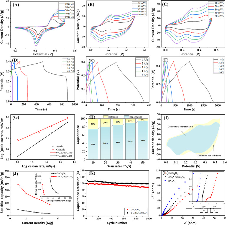
The electrochemical properties of the materials were assessed using CV and GCD studies. Fig. 4A–C present the CV curves of g-C3N4, CuCo2O4 and g-C3N4/CuCo2O4 at scan rates ranging from 10 to 50 mV s−1. The CV curves display distinct redox peaks, indicating reversible redox reactions involving the Cu+/Cu2+ and Co3+/Co4+ couples intricately linked with hydroxide ions (OH−) at the electrode–electrolyte interface. Fig. 4D–F depict the GCD curves obtained within a potential window at different current densities. The nonlinear characteristics of these curves suggest pseudocapacitive behavior. To further assess the reaction kinetics and charge storage processes in the g-C3N4/CuCo2O4 electrode, a power law approach is applied to represent the relationship between the peak current (i) and the scan rate (v) using formulas (4) and (5).
| iv = k1v + k2v1/2 | 4 |
| iv/v1/2 = k1v1/2 + k2 | 5 |
Fig. 4. The electrochemical properties of g-C3N4, CuCo2O4 and g-C3N4/CuCo2O4. (A)–(C) The CV curves of g-C3N4 (A), CuCo2O4 (B), and g-C3N4/CuCo2O4 (C). (D)–(F) GCD curves of g-C3N4 (D), CuCo2O4 (E), and g-C3N4/CuCo2O4 (F). (G) The relationship between log(v) and log(i) of g-C3N4/CuCo2O4 for the redox peaks in the CV curves for a 6.0 M KOH electrolyte. (H) Histograms of the capacitance contributions from the CV curve of g-C3N4/CuCo2O4. (I) Relative contribution of capacitance. (J) The specific capacities of CuCo2O4 and g-C3N4/CuCo2O4 under different discharge current densities and inset showing energy density and power density. (K) The cycling stabilities of CuCo2O4 and g-C3N4/CuCo2O4 electrodes. (L) EIS spectra of g-C3N4, CuCo2O4 and g-C3N4/CuCo2O4 electrodes.
The values of k1 and k2 can be determined by plotting iv/v1/2 against v1/2. As illustrated in Fig. 4G, the fitting results for i versus v1/2 reveal a strong linear correlation, suggesting that the charge storage mechanism is governed by the diffusion of electrolyte ions, thereby confirming the battery-type characteristics of g-C3N4/CuCo2O4.31,32 Ultimately, the fraction of current can be described for the charge storage process controlled by both diffusion and capacitance. The percentages of the capacitance-controlled contribution at varying sweep rates of 10, 20, 30, 40, and 50 mV s−1 are calculated to be 74%, 80%, 84%, 89%, and 93% of the total capacitance, respectively (Fig. 4H). Fig. 4I illustrates the CV profile of the g-C3N4/CuCo2O4 electrode at a sweep rate of 30 mV s−1, which is categorized into capacitance-controlled (blue region) and diffusion-controlled (yellow region) contributions. The proportion of the capacitance-controlled contribution relative to the overall performance is 84% at 30 mV s−1. The results indicate that at lower sweep rates, the diffusion-controlled process significantly influences the overall electrochemical behavior, implying that g-C3N4/CuCo2O4 facilitates the easy penetration of OH− ions.33 In marked contrast, at higher sweep rates, the capacitance's contribution becomes more pronounced due to the constrained intercalation of electrolyte ions.34 The high rate capability of the g-C3N4/CuCo2O4 electrode may be attributed to the combined effects of both capacitance-controlled and diffusion-controlled contributions that enhance the redox reactions.
The pure g-C3N4 exhibits low specific capacity and rate property due to its limited electrical conductivity. Under current densities of 0.02, 0.04, 0.05, 1, 2, and 3 A g−1, the specific capacities are 20.6, 18.6, 16.7, 13.8, 11.3, and 9.75 mA h g−1, respectively. In contrast, CuCo2O4 and g-C3N4/CuCo2O4 demonstrate much higher performance. At different discharge current densities of 1, 2, 3, 4, and 5 A g−1, the CuCo2O4 electrode demonstrates specific capacitance values of 48.3, 37.6, 28.4, 20.7, and 18.7 mA h g−1, while the g-C3N4/CuCo2O4 electrode exhibits significantly higher specific capacitance values of 247.5, 175, 145, 119.2 and 87.0 mA h g−1, respectively (Fig. 4J). At any charging rate, the specific capacitance of g-C3N4/CuCo2O4 is at least triple that of pure CuCo2O4, suggesting a synergistic effect between g-C3N4 and CuCo2O4. The device achieves an energy density of 56.25 W h kg−1 and a peak power density of 1.38 kW kg−1, as shown in the inset of Fig. 4J. Fig. 4K shows the results of cycling stability tests. After 1000 cycles at a current density of 5 A g−1, the capacitance retention for the CuCo2O4 electrode is approximately 88%, indicating a loss of function. In contrast, the g-C3N4/CuCo2O4 electrode demonstrates a capacitance retention of 98%, representing an improvement of 10% over the CuCo2O4 electrode. This improvement is comparable with that of CuCo2O4-based nanocomposites reported in the literature.16,35 The improved stability can be attributed to the effective interaction between the uniformly distributed CuCo2O4 nanoflowers and few-layer g-C3N4, facilitating electron transport and mitigating the detrimental effects of voltage drop, particularly under high-rate operating conditions. This enhancement in stability is vital for optimizing performance and ensuring reliability in various applications.
To examine the charge transport dynamics of electrodes within the electrolyte, EIS analysis was performed on the CuCo2O4 and g-C3N4/CuCo2O4 electrodes, as shown in Fig. 4L. Incorporating g-C3N4 into CuCo2O4 results in a steeper slope in the EIS diagrams of the electrodes, indicating that the kinetics of the ion diffusion process is enhanced. The equivalent circuit model is fitted to evaluate the performance of the supercapacitor electrode (inset in Fig. 4L). The incorporation of g-C3N4 narrows the band gap, leading to enhanced conductivity of the electrode through decreasing the charge transfer resistance (Rct) and series resistance (Rs).
A notable constraint in the commercial advancement of supercapacitors is the low energy density. As a result, considerable research initiatives have focused on improving the energy density of supercapacitors while preserving their high power density. Typically, supercapacitors are divided into symmetric and asymmetric types, depending on the electrode materials utilized for the negative and positive electrodes. Asymmetric devices have the ability to store a significantly greater amount of charge across a wider spectrum of operating potentials compared to their symmetric counterparts. This enhanced capacity is due to the utilization of distinct electrode materials, enabling the operating voltage of the device to surpass the thermodynamic decomposition voltage of water (1.2 V). Thus, we configure an active carbon (AC) electrode as the negative electrode and the g-C3N4/CuCo2O4 electrode as the positive electrode to construct an asymmetric supercapacitor.
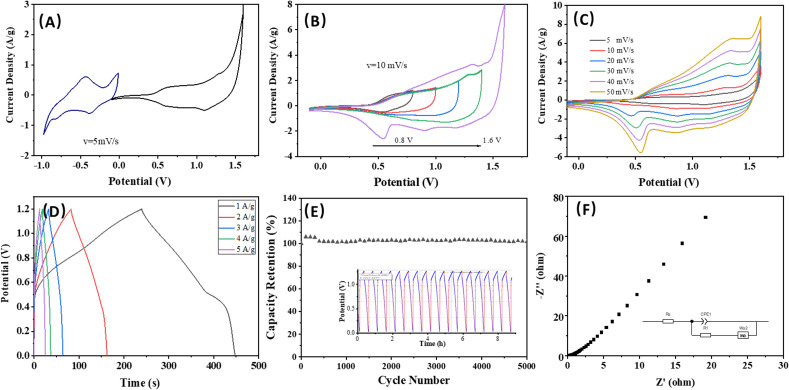
Fig. 5A illustrates the CV curves for the asymmetric device at a scan rate of 5 mV s−1 following charge balancing. In Fig. 5B, the CV profile is obtained across various voltage windows to identify the stable operating voltage of the asymmetric device. Notably, the working voltage of the asymmetric supercapacitor can be increased to 1.6 V when using an aqueous KOH electrolyte, surpassing that of conventional aqueous electrolyte AC supercapacitors. Fig. 5C depicts the representative CV curves of the device at different scan rates within a voltage range of −0.1 to 1.6 V. The shapes of all the CV curves are nearly identical, demonstrating excellent rate capability, high reversibility, and minimal internal resistance of the device. The GCD curves of the asymmetric device are shown in Fig. 5D, displaying that the device achieves a high energy density of 11.53 W h kg−1 and power density of 3.63 kW kg−1. Fig. 5E reveals that the device successfully retained 98% of its specific capacitance after undergoing 5000 cycles at a current density of 5 A g−1. This significant retention of capacitance not only demonstrates the device's strong performance but also confirms its excellent cycling stability, suggesting that it can reliably function over extended periods, making it a promising candidate for practical applications in energy storage solutions. The EIS measurement reaffirms the minimal internal resistance and the low charge/mass transfer resistance of the asymmetric device (Fig. 5F), which contributes to its good supercapacitance performance.
Fig. 5. The electrochemical properties of asymmetric device (g-C3N4/CuCo2O4 with AC). (A) The CV curves of g-C3N4/CuCo2O4 and AC electrodes at a scan rate of 5 mV s−1. (B) The potential window variation for the upper potential windows for the asymmetric device. (C) The CV curves at different scan rates from 5 to 50 mV s−1. (D) The GCD curves of the asymmetric device. (E) The capacity retention after 5000 cycles. (F) Nyquist plot.
4. Conclusions
In conclusion, flower-like g-C3N4/CuCo2O4 structures have been successfully established by decorating g-C3N4 on CuCo2O4 nanostructures. The integration of g-C3N4 into CuCo2O4 electrodes has demonstrated significant improvements in electrochemical performance. Through CV and GCD analyses, the g-C3N4/CuCo2O4 heterostructure exhibits enhanced specific capacitance values and cycling stability compared to the unmodified CuCo2O4 electrode. Furthermore, EIS testing reveals that the incorporation of g-C3N4 leads to reduced charge transfer resistance and series resistance, indicating improved kinetics of ion diffusion and enhanced conductivity. These findings highlight the crucial role of the g-C3N4/CuCo2O4 structure in promoting extensive redox reactions, fast kinetics, and sufficient active sites for electrochemical reactions. These outstanding results indicate the significant potential applications as low-cost electrode materials. By employing a comparable approach for the precise synthesis of mesostructured metal oxides and g-C3N4, the efficiency of these advanced energy storage electrode materials can be enhanced, setting the stage for future advancements.
Data availability
The data supporting the findings of this study are available within the article and further inquiries can be directed to the corresponding authors.
Author contributions
Conceptualization, Y. F.; methodology, L. M., Y. F., S. Y.; validation, S. H., X. H.; formal analysis, L. M.; resources, L. M., S. H., X. H.; data curation, L. M., Y. F., S. Y.; writing – original draft, L. M., Y. F.; writing – review & editing, L. M., Y. F.; investigation, L. M., Y. F., S. Y., S. Z., S. H., X. H.; visualization, L. M.; supervision, L. M.; funding acquisition, L. M., Y. F.
Conflicts of interest
The authors declare no conflict of interest.
Acknowledgments
This work was support by the Zunyi Technology and Big Data Bureau, Moutai Institute Joint Science and Technology Research and Development Project (ZSKHHZ [2021] No. 329); the Guizhou Provincial Engineering Research Center of Higher Education Institutions (KY[2020]022); the High-Level Talents Project of Moutai Institute (mygccrc[2022]087, mygccrc[2022]090); and the Guizhou Provincial Teaching Reform Project (2021365).
Notes and references
- Basavaraju S. K. Chavati G. B. Yanjerappa A. N. Venkatesh K. Venkateswarlu M. Muralidhara H. B. ACS Appl. Electron. Mater. 2023;5:3698–3707. [Google Scholar]
- Fu S. Liang B. Li Y. Lai S. Li L. Feng T. Li G. Inorg. Chem. 2022;61:2576–2586. doi: 10.1021/acs.inorgchem.1c03541. [DOI] [PubMed] [Google Scholar]
- Ren G. Li Y. Zhang J. Duan Y. Si Y. Yan C. Energy Convers. Manage. 2024;306:118298. [Google Scholar]
- Hu C. Liu P. Song Z. Lv Y. Duan H. Xie L. Miao L. Liu M. Gan L. Chin. Chem. Lett. 2025;36:110381. [Google Scholar]
- Liu Y. L. Yan C. Wang G. G. Zhang H. Y. Dang L. Y. Wu B. W. Lin Z. Q. An X. S. Han J. ACS Appl. Mater. Interfaces. 2019;11:9984–9993. doi: 10.1021/acsami.8b21803. [DOI] [PubMed] [Google Scholar]
- Li J. Yu H. Lv Y. Cai Z. Shen Y. Ruhlmann L. Gan L. Liu M. Nanotechnology. 2024;35:152001. doi: 10.1088/1361-6528/ad18e2. [DOI] [PubMed] [Google Scholar]
- Yang X. Hu C. Chen Y. Song Z. Miao L. Lv Y. Duan H. Liu M. Gan L. J. Energy Storage. 2024;104:114509. [Google Scholar]
- Vijayakumar S. Lee S. H. Ryu K. S. Electrochim. Acta. 2015;182:979–986. [Google Scholar]
- Cheng J. Yan H. Lu Y. Qiu K. Hou X. Xu J. Han L. Liu X. Kim J. K. Luo Y. J. Mater. Chem. A. 2015;3:9769–9776. [Google Scholar]
- Pendashteh A. Moosavifard S. E. Rahmanifar M. S. Wang Y. El-Kady M. F. Kaner R. B. Mousavi M. F. Chem. Mater. 2015;27:3919–3926. [Google Scholar]
- Liao L. Zhang H. Li W. Huang X. Xiao Z. Xu K. Yang J. Zou R. Hu J. J. Alloys Compd. 2017;695:3503–3510. [Google Scholar]
- Chen L. Lin R. Yan C. Mater. Lett. 2019;235:6–10. [Google Scholar]
- Naik K. K. Sahoo S. Rout C. S. Microporous Mesoporous Mater. 2017;244:226–234. [Google Scholar]
- Shanmugavani A. Selvan R. K. Electrochim. Acta. 2016;188:852–862. [Google Scholar]
- Liu S. Hui K. S. Hui K. N. Yun J. M. Kim K. H. J. Mater. Chem. A. 2016;4:8061–8071. [Google Scholar]
- Wei G. Zhao X. Du K. Huang Y. An C. Electrochim. Acta. 2018;283:248–259. [Google Scholar]
- Xua X. Liu Y. Dong P. Ajayand P. M. Shena J. Ye M. J. Power Sources. 2018;400:96–103. [Google Scholar]
- Vijayakumar N. Thirugnanasundar A. J. Mater. Sci.: Mater. Electron. 2024;35:1820. [Google Scholar]
- Thali B. G. Kamble R. M. J. Solid State Electrochem. 2024;28:3297–3311. [Google Scholar]
- Wang C. Liu Y. Sun Y. Xu J. Liu J. Appl. Surf. Sci. 2024;653:159407. [Google Scholar]
- Wang X. Hu M. Yao Z. Yang L. J. Phys. D: Appl. Phys. 2024;57:375502–375513. [Google Scholar]
- Xie S. Gou J. Liu B. Liu C. J. Colloid Interface Sci. 2019;540:306–314. doi: 10.1016/j.jcis.2019.01.030. [DOI] [PubMed] [Google Scholar]
- Ma L. Wang G. Jiang C. Bao H. Xu Q. Appl. Surf. Sci. 2018;430:263–272. [Google Scholar]
- Raapa N. R. Enterríaa M. Martinsb J. I. Pereiraa M. F. R. Figueiredoa J. L. ACS Appl. Mater. Interfaces. 2019;11:6066–6077. doi: 10.1021/acsami.8b19246. [DOI] [PubMed] [Google Scholar]
- Sun W. Wang Y. Wu H. T. Wang Z. H. Rooney D. Sun K. N. Chem. Commun. 2017;53:8711–8714. doi: 10.1039/c7cc02621h. [DOI] [PubMed] [Google Scholar]
- Abbasi L. Arvand M. Appl. Surf. Sci. 2018;445:272–280. [Google Scholar]
- Pang M. Jiang S. Zhao J. Zhang S. Liu R. Qu W. Pan Q. Xing B. Gua L. Wang H. New J. Chem. 2018;42:19153–19163. [Google Scholar]
- Kaverlavania S. K. Moosavifard S. E. Bakouei A. J. Mater. Chem. A. 2017;15:14301–14309. [Google Scholar]
- Zhan Z. Y. Chen S. J. Xie J. L. Yang Y. F. Xiong J. J. Alloys Compd. 2017;722:928–937. [Google Scholar]
- Xing Z. Ju Z. Zhao Y. Qian Y. Sci. Rep. 2016;6:26146. doi: 10.1038/srep26146. [DOI] [PMC free article] [PubMed] [Google Scholar]
- Kuang M. Liu X. Dong F. Zhang Y. J. Mater. Chem. A. 2015;3:21528–21536. [Google Scholar]
- Zhang Y. Xu J. Zheng Y. Zhang Y. Hu X. Xu T. RSC Adv. 2017;7:3983–3991. [Google Scholar]
- Zhang Y. ChemElectroChem. 2017;4:721–727. [Google Scholar]
- Wang Y. Yang D. Lian J. Pan J. Wei T. Sun Y. J. Alloys Compd. 2018;735:2046–2052. [Google Scholar]
- Mohammadi A. Moosavifard S. E. Tabrizi A. G. Abdi M. M. Karimi G. ACS Appl. Energy Mater. 2019;2:627–635. [Google Scholar]
Associated Data
This section collects any data citations, data availability statements, or supplementary materials included in this article.
Data Availability Statement
The data supporting the findings of this study are available within the article and further inquiries can be directed to the corresponding authors.


