Abstract
In trenchless pipe jacking engineering practice, the formation of high-quality slurry jacket on the outer wall of pipe section is the key to effectively reducing the pipe-soil frictional resistance, improving the construction efficiency, reducing the construction risk and ensuring the construction safety. Herein, the multifunctional experimental apparatus for the pipe-soil frictional resistance testing is improved to ensure the smooth implementation of the subsequent experimental research. The influences of the structural parameters of grouting holes in circular and rectangular pipe sections on the pipe-soil frictional resistance and the states of slurry jackets around the various pipe sections are investigated respectively based on orthogonal experiment. Key findings include the pipe-soil frictional resistances increase with the increase of the spacing between adjacent grouting holes and the deflection angle of grouting holes, the layout of grouting holes has the greatest influence on pipe-soil frictional resistance, reasonable and uniform layout of grouting holes around the pipe sections can form more complete high-quality slurry jackets, to show better pipe-soil frictional resistance reduction effect. Moreover, the optimal structural parameters of grouting holes in circular and rectangular pipe sections are the same, i.e. the layout is triple grouting holes, the spacing between adjacent grouting holes S is 417 mm, and the deflection angle of grouting holes α is 40°. These insights could provide some scientific and valuable guidance for pipe-soil frictional resistance reduction during trenchless pipe jacking.
Keywords: Trenchless technology, Pipe jacking, Pipe-soil frictional resistance, Grouting holes, Slurry jacket, Lubrication and friction reduction
Subject terms: Civil engineering, Environmental impact
Introduction
Different from the traditional open-cut construction method, trenchless technology is an environmentally friendly, green, low-carbon and efficient construction method for underground infrastructure with minimal disruption to surface structure, traffic, business, and other activities, which focuses on inspection, new installation, rehabilitation and replacement of underground infrastructure, especially for the various pipelines, culvert, passage, etc. Its construction methods mainly include pipe jacking, horizontal directional drilling (HDD), auger boring, pipe ramming, cured-in-place pipe (CIPP), spray-in-place pipe (SIPP), etc1–3. Nowadays, it has been widely used in the development and utilization of underground space and the construction of underground infrastructure1–20.
Pipe jacking is one of the new installation of trenchless technology, its technical principle is to use the jacking force provided by the main jacking cylinder and other jacking equipment in the launching shaft to push the pipe jacking machine forward from the launching shaft according to the predetermined design trajectory, through the formation until it reaches the arriving shaft. In this process, the pipe sections following the pipe jacking machine can be simultaneously laid one by one between the two shafts, and several pipe sections are connected to form a complete underground infrastructure1–5. However, with the gradual extension of the jacking distance, the number of pipe sections required to be jacking forward also increases correspondingly, and the jacking force required by the jacking equipment also increases continuously, especially under the working conditions of large burial depth, large pipe diameter, long distance and complex jacking trajectory, which also causes difficulties in jacking pipe sections forward, pipe sections stuck, back support wall cracking and other construction problems, and even serious engineering accidents. Many theoretical and experimental studies, as well as engineering practice, show that effectively reducing pipe-soil frictional resistance is the key to avoiding the above problems and ensure the smooth implementation of trenchless pipe jacking1,2,4–8.
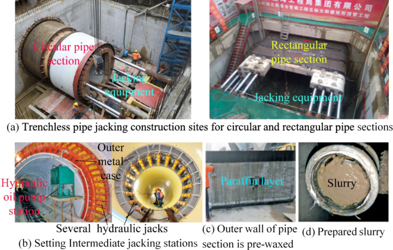
Currently, the pipe-soil frictional resistance reduction measures used in the process of trenchless pipe jacking mainly include setting several intermediate jacking stations, applying lubricating materials such as paraffin, and grouting to form slurry jacket, as shown in Fig. 1. Among them, considering the objective factors of long-term effectiveness of pipe-soil frictional resistance reduction, safety, comprehensive cost and operation difficulty, grouting to form slurry jacket is generally adopted in most pipe jacking engineering practices1,2,4–20. Slurry composed of bentonite, water and other treatment agents is continuously injected into the annular gap between the outer wall of pipe sections and formation to form the slurry jacket with lubrication and pipe-soil frictional resistance reduction characteristics on the outer wall of pipe sections. In fact, the slurry jacket can not only reduce the pipe-soil frictional resistance effectively, but also support and strengthen the formation, reduce the formation disturbance and settlement deformation, and ensure the safety and control of the surrounding environment during pipe jacking construction4,7,10–20.
Fig. 1.
Current measures for reducing pipe-soil frictional resistance during trenchless pipe jacking15.
The aspects of pipe-soil frictional resistances, jacking force estimation, surface settlement, formula of lubricating slurry, pipe-slurry-soil interaction have been studied by many scholars. Wen et al.1 proposed the comparative analysis of pipe-soil frictional resistances of jacking circular and rectangular pipe sections based on experimental test, theoretical calculation and discrete element numerical simulation, the frequently used theoretical calculation equations and empirical estimation equations of pipe-soil frictional resistance for pipe jacking have been modified. Ma et al.2,19, Deng et al.4, Kong et al.5, Wen et al.6,7 and Ji et al.8 mainly investigated on the jacking force estimation and surface settlement for pipe jacking based on experimental test, theoretical calculation, numerical simulation and field monitoring, the estimation methods of jacking force and the laws of surface settlement obtained could provide some valuable reference for pipe jack engineering practice. Liu et al.10, Liu et al.12 and Yang et al.20 conducted the formula of lubricating slurry optimization and proposed the high-quality slurry formula with good performance. Liu et al.9, Cui et al.11, Ye et al.10, Yang et al.16, Namli et al.17 and Zhou et al.18 discussed on the pipe-slurry-soil interaction, and proposed the mechanism of slurry jacket can reduce the pipe-soil frictional resistance. However, the influence of the structural parameters of grouting holes in pipe sections on the pipe-soil frictional resistance has not been reported. In fact, the structural parameters of grouting holes play a very important role in the pipe-soil frictional resistance reduction effect, because the different grouting holes will directly determine the location, quantity, direction and way of injecting lubricating slurry into the annular gap between the outer wall of pipe sections and formation, resulting in the performance of forming slurry jacket on the outer wall of pipe section.
In this paper, orthogonal experiments are conducted to study the influence of grouting holes’ structural parameters (i.e., the layout of grouting holes, the spacing between adjacent grouting holes and the deflection angle of grouting holes) in circular and rectangular pipe sections on pipe-soil frictional resistance based on the self-developed improved multifunctional experimental apparatus for the pipe-soil frictional resistance testing. Moreover, the influences of grouting holes’ structural parameters on pipe-soil frictional resistance and the slurry jacket states of jacking circular and rectangular pipe sections are investigated, the optimal structural parameters of grouting holes are obtained. The relevant results and conclusions can provide some scientific and valuable guidance for effectively solving the problems of lubrication and pipe-soil frictional resistance reduction during trenchless pipe jacking engineering practice.
Materials and methods
The improved multifunctional experimental apparatus
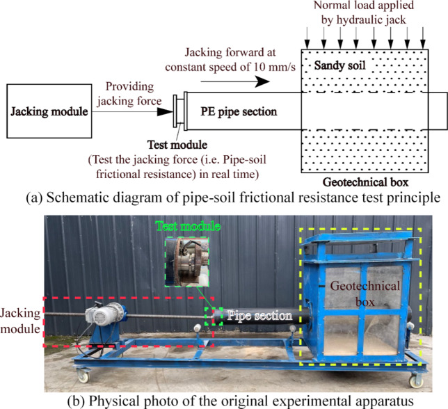
The original multifunctional experimental apparatus for the pipe-soil frictional resistance testing was independently designed and developed as shown in Fig. 2. It mainly consists of geotechnical box module, pipe section, jacking module and test module, the more detailed information can be found in reference [1].
Fig. 2.
The original multifunctional experimental apparatus for the pipe-soil frictional resistance testing during trenchless pipe jacking.
Although the original multifunctional experimental apparatus can meet the general requirements of pipe-soil frictional resistance testing, it still has the following major defects:
Because only one set of jacking module is set on one side of the experimental apparatus, when the pipe section is jacked forward by the variable frequency motor until the end of an experiment, it is very difficult to push the pipe section back to the starting position by manpower. Usually, after the end of an experiment, all the soil filled in the geotechnical box needs to be dug out, and then refill the soil after the pipe section is restored for the next experiment. This not only increases the labor intensity of the experimenters, but also greatly reduces the efficiency of the experiment.
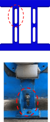
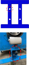
The variable frequency motor and the guide sheaves are fixed to the bottom support by bolts, and the corresponding bolt holes are long strip shape, they are easy to loosen the connection of the variable frequency motor, guide sheaves and bottom support. Moreover, the base of guide sheave is vertical, the upper part of guide sheave can slide up and down along the vertical bolt hole. Thus, when the jacking force is large during the experiment, the variable frequency motor and the guide sheaves will be offset. As a result, the pipe section is further offset in the jacking direction. The whole experiment process will become unstable, which will adversely affect the experimental data and results.
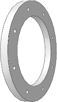
The structure of the original sealing flange end covers has a design defect. Because the end faces of the sealing flange end covers are flat, it makes when the sealing flange end covers are firmly connected with the through holes on both sides of geotechnical box, the wall thickness of geotechnical box causes the dimensional difference (i.e., a circle step was created) between the end faces of sealing flange end covers and the two sides of geotechnical box. It makes more sandy soil filled in geotechnical box easily leak out from the circular step gap during the experimental process of pipe jacking, which leads to a certain error in the experimental test results. In addition, if the geotechnical box is filled with pebbles of large particle size, it is easy to cause the pebbles to get stuck at the circle step, and then cause the pipe section to be stuck, so it is very difficult to jack the pipe section smoothly, resulting in the pipe jacking experiment is difficult to carry out normally.
In view of the above three defects, the improved schemes of the original experimental apparatus are proposed as follows:
Extending the length of bottom support, to allow another jacking module can be added symmetrically on the other side of the experimental apparatus, and the improved experimental apparatus becomes a mirror symmetric structure centered on the geotechnical box. Thus, in the experimental process of pipe jacking, when the pipe-soil frictional resistance test is completed by jacking the pipe section forward from one end of the experimental apparatus to the other end, the pipe section can be reverse jacked to the initial position through the jacking module set on the other side of the experimental apparatus. The benefits of this approach mainly include two aspects: First, the reverse jacking pipe section is realized by the power output of the variable frequency motor, which can effectively reduce the labor intensity of the experimenters. Second, the pipe-soil frictional resistance can be measured during the reciprocating jacking pipe section, which effectively doubles the efficiency and shorten the time required for the experimental test.
The structures of the bolt holes are optimized to be round holes, and the bases of guide sheaves are optimized for right-angle shape, so the freedom of movement of the variable frequency motor and the guide sheaves is effectively limited. Thus, in the experimental process of pipe jacking, the variable frequency motor and the guide sheaves become very stable, ensuring the smooth movement of the pipe section, and the test accuracy of pipe-soil frictional resistance is also guaranteed.
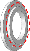
The plane structure of the original sealing flange end covers close to the geotechnical box is optimized to protrude into the circle stepped shape, and the protruding part is just used to fill the annular step gap between the plane sealing flange end covers and one side of the geotechnical box caused by its wall thickness, effectively improving the sealing performance and reduce the soil particles loss.
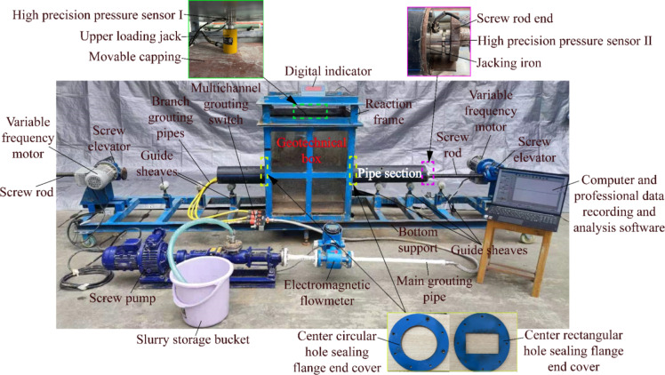
In addition, to better restore the construction process of pipe jacking, it is hoped to simulate the pipe-soil frictional resistance reduction process of slurry jacket formed by grouting lubricating slurry into the annular gap between pipe section and formation by experiments, to further expand the composition and function of the experimental apparatus. The grouting module is added on the basis of the original experimental apparatus. It mainly consists of screw pump, electromagnetic flowmeter, main grouting pipe, multichannel grouting switch, branch grouting pipes. Among them, the screw pump is used to pump out the lubricating slurry from the slurry storage bucket, its model is G20-1, the corresponding rated pump flow rate is 0.8 m3/h, the rated pump pressure is 0.6 MPa, the motor power is 0.75 kW, and it requires a 380 V power supply. Moreover, the customized electromagnetic flowmeter is used to measure slurry flow in real time, its nominal pressure is 1.6 MPa, its nominal diameter is DN20. The inner diameter of main grouting pipe is 20 mm, one end of it is connected with the hydraulic end outlet of screw pump, the electromagnetic flowmeter is installed on the main grouting pipe, and it is more than 10 cm away from the screw pump, the other end of the main grouting pipe connects to the multichannel grouting switch. The other end of the multichannel grouting switch is connected to multiple branch grouting pipes, it is used to control the flow or closure of the slurry in different branch grouting pipes. The outer diameter of branch grouting pipes is 12 mm, which is to match the diameter of the grouting holes machined in the pipe section. The other ends of the branch grouting pipes are inserted into the various grouting holes through the internal cavity of pipe section respectively, and the exit end of the branch grouting pipes are flush with the outer wall of pipe section without being exposed, to ensure smooth grouting without affecting the normal forward jacking pipe section. Furthermore, the corresponding improved details of the original multifunctional experimental apparatus are listed in Table 1, and the physical photo of the improved multifunctional experimental apparatus is shown in Fig. 3.
Table 1.
The corresponding improved details of the original multifunctional experimental apparatus.
| Improved part | Original structure | Improved structure | Improved description |
|---|---|---|---|
| Jacking module |

|

|
Extending the length of bottom support, to symmetrically add another jacking module on the other side. |
|
Bolt holes of the variable frequency motor and the guide sheaves. The vertical bases of guide sheaves. |
|
|
The long strip shape of bolt holes is optimized to be round holes. Moreover, the vertical base of guide sheave is optimized for right-angle shape, and the upper part of guide sheave is firmly connected with the horizontal side of the right-angle base. |
| Sealing flange end covers |
|
|
One side of the sealing flange end covers is optimized for prominent structure, which can match the annular step gap on the side connected to the geotechnical box, effectively improve the sealing performance and reduce the soil particles loss. |
| Grouting module | None. |

|
Adding the grouting module to expand the function of the experimental apparatus effectively. The formation process of slurry jacket and its lubrication and frictional reduction performance for the relative motion of the pipe section and the soil can be tested experimentally. |
Fig. 3.
The improved multifunctional experimental apparatus for the pipe-soil frictional resistance testing.
Structural design of grouting holes in pipe sections based on the orthogonal experiment
Many experimental studies and engineering practices show that the state of slurry jacket formed around the pipe section outer wall is one of the most important factors affecting the pipe-soil frictional resistance reduction during pipe jacking, and the formation of slurry jacket is mainly determined by the structural parameters of the grouting holes machined in the pipe section. Herein, the structural parameters of grouting holes considered mainly include the layout of grouting holes, the spacing between adjacent grouting holes S, and the deflection angle of grouting holes α. Taking the pipe-soil frictional resistance as the evaluation indicator, the above three key factors are selected to carry out the orthogonal experimental design of grouting holes’ structure. Moreover, due to the influence of gravity, the slurry grouting into the annular gap between the outer wall of pipe section and the formation is easy to flow to the bottom of pipe section and permeate into the lower formation. To ensure the retention of slurry in the area around the pipe section as much as possible to form a high-quality slurry jacket, the grouting holes in the circular and rectangular pipe sections designed in this study are all located on the upper and both sides of the pipe sections. The current relevant standards and specifications related to pipe jacking, some typical pipe jacking engineering practices in China, and the suitable specifications for machining grouting holes in pipe sections and purchasing grouting pipes convenient are considered comprehensively, the diameter of all grouting holes is 12 mm.
Layout of grouting holes
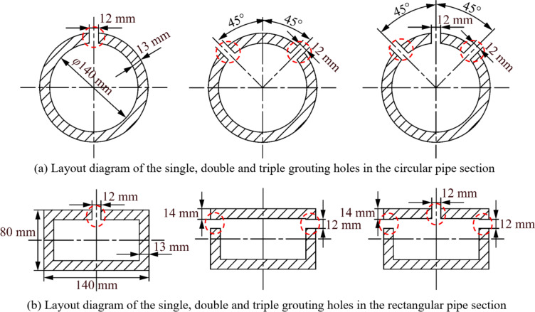
The layout of grouting holes can be divided into three types, i.e. single grouting hole, double grouting holes and triple grouting holes. As shown in Fig. 4, the single grouting hole is in the middle of the circular and rectangular pipe sections. Furthermore, for the circular pipe section, the double grouting holes are in the direction of 45° angle on each side of its center line, and the triple grouting holes are equivalent to combining a single grouting hole and double grouting holes, i.e. one of the triple grouting holes is in the middle, and the other two holes are in the direction of 45° angle on each side of its center line. Meanwhile, for the rectangular pipe section, the double grouting holes are located on its left and right short sides and 14 mm from the top, and the triple grouting holes are also equivalent to combining a single grouting hole and double grouting holes, i.e. one of the triple grouting holes is in the middle, and the other two holes are located on its left and right short sides and 14 mm from the top.
Fig. 4.
Layout diagram of grouting holes in the circular and rectangular pipe sections.
Spacing between adjacent grouting holes
In this study, the length of pipe sections is all 1600 mm, the length of geotechnical box is 600 mm. All the pipe sections are inserted and passed through the geotechnical box, and the 50 mm length of pipe sections are exposed to the outside of geotechnical box during each pipe jacking experiment in advance. As shown in Fig. 5, three sections of grouting holes are set on all pipe sections. Among them, the first section of grouting holes is arranged in the middle part of the pipe section buried in the geotechnical box, i.e. 350 mm away from the end of pipe section. The length from the second section of grouting holes to the first section of grouting holes and from it to the third section of grouting holes is equal, i.e. the length is S, the rest length of pipe section is S′.
Fig. 5.
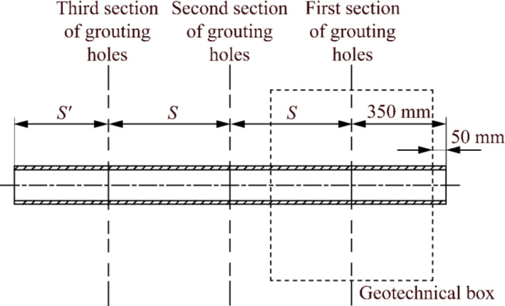
Schematic diagram of the spacing between adjacent grouting holes in the pipe sections.
Deflection angle of grouting holes
The deflection angle of grouting holes means the angle between the axis of grouting hole and the jacking direction, which is recorded as α, as shown in Fig. 6. Generally, the deflection angle of grouting holes is 90° during the ordinary trenchless pipe jacking construction, i.e. the axis of grouting hole is perpendicular to the jacking direction. Actually, the deflection angle of grouting holes directly affects the grouting pressure, flow rate and angle of slurry, resulting in the state of slurry jacket and its lubrication and frictional resistance reduction performance are directly affected. In this study, the deflection angle ranges from 40° to 90°.
Fig. 6.

Schematic diagram of the deflection angle α of grouting holes in the pipe sections.
Orthogonal table and orthogonal experimental scheme design
As mentioned above, the number of key factors in the structural parameters of grouting holes is three, and each factor contains three levels. Thus, the appropriate orthogonal table can be selected as L9(34). The detailed factors and levels of the orthogonal experiment are listed in Table 2, and the detailed design schemes of the orthogonal experiment are listed in Table 3.
Table 2.
The detailed factors and levels of the orthogonal experiment.
| Levels | Factors | ||
|---|---|---|---|
| A | B | C | |
| Layout of grouting holes | Spacing between adjacent grouting holes S (mm) | Deflection angle of grouting holes α (°) | |
| 1 | Single grouting hole | 417 | 40 |
| 2 | Double grouting holes | 467 | 65 |
| 3 | Triple grouting holes | 517 | 90 |
Table 3.
The detailed design schemes of the orthogonal experiment.
| Experimental number | A | Empty | B | C |
|---|---|---|---|---|
| 1 | 1 (Single grouting hole) | 1 | 1 (417 mm) | 1 (40°) |
| 2 | 1 | 2 | 2 (467 mm) | 2 (65°) |
| 3 | 1 | 3 | 3 (517 mm) | 3 (90°) |
| 4 | 2 (Double grouting holes) | 1 | 2 | 3 |
| 5 | 2 | 2 | 3 | 1 |
| 6 | 2 | 3 | 1 | 2 |
| 7 | 3 (Triple grouting holes) | 1 | 3 | 2 |
| 8 | 3 | 2 | 1 | 3 |
| 9 | 3 | 3 | 2 | 1 |
Experimental preparation and procedure
The experimental preparation mainly includes two aspects as follows: First, it is necessary to prepare the slurry used for pipe section lubrication to reduce the pipe-soil frictional resistance during pipe jacking, which is prepared by bentonite, carboxymethyl cellulose (CMC), sodium carbonate and water in a certain proportion. Among them, bentonite is a clay with montmorillonite, potassium and calcium as the main components. After mixing with water, bentonite has certain expansibility and thixotropy, which are also two basic properties of slurry. The role of CMC in slurry is mainly thickener and stabilizer, and the sodium element in it helps to bind bentonite to water. Furthermore, sodium carbonate is easily soluble in water, and its main role in slurry is as a dispersant, where Na+ exchange with Ca2+ in bentonite, resulting in hydration reaction, which can effectively promote the combination ability of solid phase and liquid phase in slurry, and enhance the stability of slurry preparation. In this study, the specific ratio of slurry is bentonite: CMC: sodium carbonate: water = 6: 0.1: 0.3: 93.6. In addition, it is also necessary to note that the slurry must be puffed (standing) for 12 h before it can be used20.
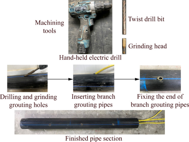
Second, as shown in Fig. 7, the drilling process of the grouting holes and the connection of corresponding branch grouting pipes are completed in pipe sections based on the design schemes of the orthogonal experiment (Table 3). Specifically, a hand-held electric drill, a twist drill bit and grinding head with the diameter of 12 mm are selected as the machining tools, grouting holes are drilled and ground in the various pipe sections according to the layout, spacing S and deflection angle α of the grouting holes designed in Table 3. Then, the branch grouting pipes with an outer diameter of 12 mm are inserted into the pipe section along the grouting holes and fixed with strong glue at the outlet of the grouting holes. The other ends of the branch grouting pipes are dragged out from the internal cavity of pipe section and connected to the multichannel grouting switch, which is connected with the main grouting pipe to form a complete grouting pipe channel.
Fig. 7.
Photos of the grouting holes drilling and branch grouting pipes connection in the pipe section.
The whole experimental procedure mainly includes the following nine steps:
Before each experimental test, fill the geotechnical box with dry sandy soil to the bottom of pipe section and tamp it firmly, then the pipe section is inserted into geotechnical box through the center hole of the sealing flange end covers until the 50 mm length of pipe section is exposed to the outside of geotechnical box along the jacking direction.
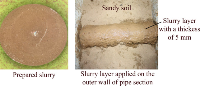
The slurry layer with a thickness of 5 mm is evenly applied on the outer wall surface of pipe section placed in the geotechnical box, as shown in Fig. 8. The main purposes are as follows: ① After the completion of an experimental test, the sand in the geotechnical box should be dug out, and the new dry sandy soil should be filled again after the pipe section is replaced, which may cause the contact condition between the sandy soil around the outer wall of pipe section and the pipe section in the process of multiple experimental test to be inconsistent. The errors of experimental tests caused by this situation can be reduced by smearing the slurry around the outer wall of pipe section in advance. ② To simulate the effect of slurry jacket formed on the outer wall of the pipe section that jacking into formation first on the jacking pipe section into formation second in the actual pipe jacking process.
Continue to fill the geotechnical box with sandy soil to 280 mm away from the top of pipe section and tamp the sandy soil.
Start the jacking module and jacking the pipe section forward at a constant speed of 10 mm/s. The test module starts to record the values of pipe-soil frictional resistance. Meanwhile, the grouting module is started to control the pumping flow of slurry at 0.18 m3/h.
To control the grouting sequence at different grouting holes, the multichannel grouting switch is turned on or closed successively in the order of the grouting section entering and exiting the geotechnical box.
When the distance of jacking pipe section reaches 0.9 m, stop grouting and experimental data collection, and save the experimental test data.
Dig out the surface sandy soil above the top of pipe section, take photos and measure the slurry permeation and diffusion state. Then, the slurry permeated sandy soil around the pipe section is removed, and the new pipe section is replaced to prepare for the next group experimental test.
Fig. 8.
Photos of the slurry prepared, and the slurry layer applied on the outer wall of pipe section.
Results and discussions
The results of orthogonal experiment
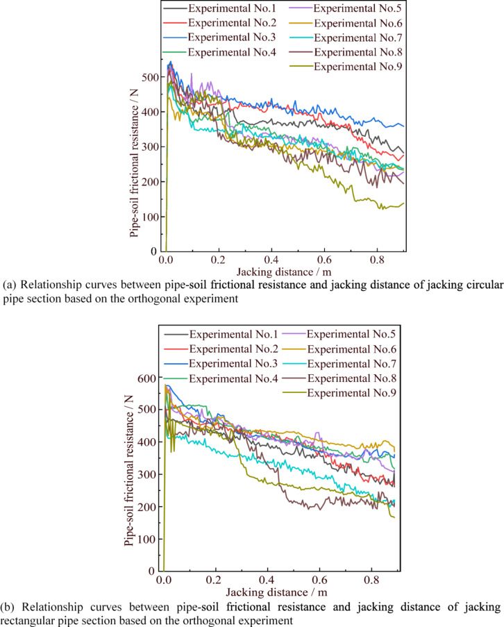
The relationship curves between pipe-soil frictional resistance and jacking distance of jacking circular and rectangular pipe sections based on the orthogonal experiment are shown in Fig. 9. We can find that with the simultaneous grouting and jacking forward, more and more slurry is injected into the sandy soil around the outer wall of pipe sections, which makes the pipe-soil frictional resistance in each group of experimental tests show a downward trend. Moreover, to ensure the accuracy of the experimental test, each group of experimental tests are repeated three times. The average value of pipe-soil frictional resistance F obtained in each group of experiments during the entire jacking process can be calculated, and the average value of the three repeated experiments  can also be calculated as the experimental result and recorded as the average pipe-soil frictional resistance of the corresponding group of experiments, which can be used as the experimental index for analysis. The results of orthogonal experiment and range analysis are listed in Table 4.
Fig. 9.
Relationship curves between pipe-soil frictional resistance and jacking distance of jacking circular and rectangular pipe sections based on the orthogonal experiment.
Table 4.
Results of the orthogonal experiment and the range analysis.
| Experimental number | Factor | Circular pipe section | Rectangular pipe section | |||||||||
|---|---|---|---|---|---|---|---|---|---|---|---|---|
| Pipe-soil frictional resistance/N | ||||||||||||
| A | Empty | B | C | F1c | F2c | F3c |

|
F1r | F2r | F3r |

|
|
| 1 | 1 | 1 | 1 | 1 | 353 | 394 | 369 | 372 | 365 | 351 | 388 | 368 |
| 2 | 1 | 2 | 2 | 2 | 398 | 395 | 371 | 388 | 385 | 417 | 371 | 391 |
| 3 | 1 | 3 | 3 | 3 | 407 | 411 | 424 | 414 | 409 | 426 | 404 | 413 |
| 4 | 2 | 1 | 2 | 3 | 317 | 338 | 338 | 331 | 428 | 397 | 417 | 414 |
| 5 | 2 | 2 | 3 | 1 | 322 | 342 | 350 | 338 | 386 | 420 | 427 | 411 |
| 6 | 2 | 3 | 1 | 2 | 322 | 301 | 298 | 307 | 434 | 425 | 422 | 427 |
| 7 | 3 | 1 | 3 | 2 | 309 | 326 | 322 | 319 | 300 | 322 | 329 | 317 |
| 8 | 3 | 2 | 1 | 3 | 292 | 327 | 299 | 306 | 308 | 298 | 321 | 309 |
| 9 | 3 | 3 | 2 | 1 | 288 | 279 | 294 | 287 | 301 | 315 | 308 | 308 |
| K 1 | 1174 | 1022 | 985 | 997 |
Shape: Circular pipe section Order of factors (primary to secondary): A > B > C Optimal scheme: A3B1C1 |
|||||||
| K 2 | 976 | 1032 | 1006 | 1014 | ||||||||
| K 3 | 912 | 1008 | 1071 | 1051 | ||||||||
| k 1 | 391.33 | 340.67 | 328.33 | 332.33 | ||||||||
| k 2 | 325.33 | 344 | 335.33 | 338 | ||||||||
| k 3 | 304 | 336 | 357 | 350.33 | ||||||||
| R | 87.33 | 8 | 28.67 | 18 | ||||||||
| K 1 | 1162 | 1089 | 1094 | 1077 |
Shape: Rectangular pipe section Order of factors (primary to secondary): A > B > C Optimal scheme: A3B1C1 |
|||||||
| K 2 | 1252 | 1111 | 1113 | 1135 | ||||||||
| K 3 | 934 | 1148 | 1141 | 1136 | ||||||||
| k 1 | 387.33 | 363 | 364.67 | 359 | ||||||||
| k 2 | 417.33 | 370.33 | 371 | 378.33 | ||||||||
| k 3 | 311.33 | 382.67 | 380.33 | 378.67 | ||||||||
| R | 106 | 19.67 | 15.67 | 19.67 | ||||||||
From Table 4, it is not difficult to find that the ranges of pipe-soil frictional resistance of jacking circular and rectangular pipe sections  are 287 N ~ 414 N and 308 N ~ 427 N, respectively. When the circular pipe sections are jacked forward in the sandy soil, the minimum pipe-soil frictional resistance appears in the experimental conditions of the layout of triple grouting holes, spacing between adjacent grouting holes S is 417 mm, and the deflection angle of grouting holes α is 40°. The corresponding maximum pipe-soil frictional resistance appears in the experimental conditions of the layout of single grouting hole, spacing between adjacent grouting holes S is 517 mm, and the deflection angle of grouting holes α is 90°. In addition, the experimental conditions of minimum pipe-soil frictional resistance when the rectangular pipe sections are jacked forward in the sandy soil are the same as that of the circular pipe sections above, i.e. the layout of triple grouting holes, spacing between adjacent grouting holes S is 417 mm, and the deflection angle of grouting holes α is 40°. The corresponding maximum pipe-soil frictional resistance appears in the experimental conditions of the layout of double grouting holes, spacing between adjacent grouting holes S is 517 mm, and the deflection angle of grouting holes α is 90°. Furthermore, the results of range analysis show that the key structural parameters of grouting holes have the same order of factors for pipe-soil frictional resistance when jacking forward circular and rectangular pipe sections in sandy soil, i.e. factor A (layout of grouting holes) is the most important factor affecting the degree of pipe-soil frictional resistance, followed by factor B (spacing between adjacent grouting holes S), and factor C (deflection angle of grouting holes α) is the least. Simultaneously, taking the reduction of pipe-soil frictional resistance as the optimization index, A3B1C1 is the optimal scheme of grouting holes’ structural parameters for both circular and rectangular pipe sections, i.e. the layout of triple grouting holes, spacing between adjacent grouting holes S is 417 mm, and the deflection angle of grouting holes α is 40°.
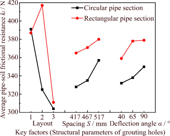
The influence of grouting holes’ structural parameters on pipe-soil frictional resistance is further analyzed, the average pipe-soil frictional resistance (ki) results obtained from the orthogonal experimental range analysis of various factors are taken as the longitudinal coordinate, and each factor and its corresponding level are taken as the horizontal coordinate to draw the trend diagram of the influence of key factors on pipe-soil frictional resistance, as shown in Fig. 10.
Fig. 10.
Trend diagram of the influence of key factors on pipe-soil frictional resistance.
As can be seen from Fig. 10, the layout of grouting holes can greatly affect the pipe-soil frictional resistance, while the spacing between adjacent grouting holes S and deflection angle of grouting holes α have relatively little influence on it. When the circular pipe sections are jacked forward in sandy soil, the pipe-soil frictional resistance is the largest under the layout of single grouting hole (391.33 N), followed by double grouting holes (325.33 N), and triple grouting holes is the least (304 N), i.e. the pipe-soil frictional resistance of double and triple grouting holes decreased by 16.9% and 22.3% respectively compared with that of single grouting hole. This shows that under the same flow rate of pumping slurry condition, when the number of grouting holes in the same section of the circular pipe section increases, the slurry can spread better around the outer wall of circular pipe section to form a more complete and uniform slurry jacket, resulting in the effect of lubrication and pipe-soil frictional resistance reduction is better. However, the experimental results for rectangular pipe sections are slightly different. When the rectangular pipe sections are jacked forward in sandy soil, the pipe-soil frictional resistance is the largest under the layout of double grouting holes (417.33 N), followed by single grouting hole (387.33 N), and triple grouting holes is the least (311.33 N), i.e. the pipe-soil frictional resistance of single and triple grouting holes decreased by 7.2% and 25.4% respectively compared with that of double grouting holes. This phenomenon may be caused by the fact that the four faces of the rectangular pipe sections are mutually perpendicular planes. Limited by the shape of the pipe section, when the number of grouting holes in the same section of rectangular pipe section is small and the distribution is uneven, the grouting slurry is easy to stay in each plane and penetrate into the sandy soil around the rectangular pipe section in large quantities, and the slurry cannot flow along the outer wall of rectangular pipe section and thus cannot form high-quality slurry jacket. It shows that the number and layout of grouting holes are more important in the pipe-soil frictional resistance reduction of jacking rectangular pipe sections.
The pipe-soil frictional resistance increases with the increase of the spacing between adjacent grouting holes S. When the spacing between adjacent grouting holes S increases from 417 mm to 517 mm, the pipe-soil frictional resistance increases by 8.8% from 328 N to 357 N for circular pipe sections, and the pipe-soil frictional resistance increases by 4.3% from 364.67 N to 380.33 N for rectangular pipe sections. The reason may be that the slurry injected into the annular gap between the outer wall of pipe sections and the sandy soil will penetrate into the surrounding soil layer, which may cause the loss of slurry around the outer wall of pipe sections. However, the increase of spacing between adjacent grouting holes S means that the waiting time for replenishment of slurry at the same part increases, and the phenomenon of slurry loss is more obvious, thus showing a larger pipe-soil frictional resistance. In addition, the pipe-soil frictional resistance increases with the increase of the deflection angle of grouting holes α. When the deflection angle of grouting holes α increases from 40° to 90°, the pipe-soil frictional resistance increases by 5.4% from 332 N to 350 N for circular pipe sections, and the pipe-soil frictional resistance increases by 5.5% from 359 N to 378.67 N for rectangular pipe sections. This phenomenon may be caused by the fact that when there is a certain deflection angle between the grouting holes and the jacking direction of pipe sections, the angle of the annular gap of the slurry injected from grouting holes can be effectively changed, resulting in the back pressure of the slurry injected is smaller, and the distance of slurry flowing along the jacking direction of pipe section is longer, which increases the contact area between the injected slurry and the outer wall of pipe section and the sandy soil around the pipe section. The amount of slurry penetrating into the sandy soil is reduced, so that a more complete and uniform lubricating slurry jacket can be formed. Meanwhile, the existence of a certain deflection angle in the grouting holes can effectively reduce the phenomenon of the soil layer around the pipe sections falling off and blocking the grouting holes.
To further analyze the significance of the influence of grouting holes’ structural parameters on pipe-soil frictional resistance, it is also necessary to conduct variance analysis on the results of orthogonal experiment, as listed in Table 5. For circular and rectangular pipe sections, different grouting holes’ structural parameters have slightly different significant effects on pipe-soil frictional resistance. Specifically, the layout of grouting holes is a significant factor, the between adjacent grouting holes S is a more significant factor, and the deflection angle of grouting holes α is an insignificant factor for circular pipe sections. Moreover, the layout of grouting holes is a more significant factor, the between adjacent grouting holes S and the deflection angle of grouting holes α are two insignificant factors for rectangular pipe sections.
Table 5.
The results of variance analysis based on the orthogonal experiment.
| Shape of pipe sections | Source of variation | Sum of squared deviations | Degree of freedom | Mean sum of squares | F-ratio | F critical values | Significance |
|---|---|---|---|---|---|---|---|
| Circular pipe sections | A | 12438.222 | 2 | 6219.111 | 128.376 | F0.1(2,2) = 9 | Significant |
| B | 1340.222 | 2 | 670.111 | 13.833 | F0.05(2,2) = 19 | More significant | |
| C | 508.222 | 2 | 254.111 | 5.245 | F0.01(2,2) = 99 | Insignificant | |
| Error e | 96.889 | 2 | 48.444 | N/A | N/A | N/A | |
| Total T | 14383.555 | 8 | N/A | N/A | N/A | N/A | |
| Rectangular pipe sections | A | 17,912 | 2 | 8956 | 30.223 | F0.1(2,2) = 9 | More significant |
| B | 372.667 | 2 | 186.333 | 0.629 | F0.05(2,2) = 19 | Insignificant | |
| C | 760.667 | 2 | 380.333 | 1.283 | F0.01(2,2) = 99 | Insignificant | |
| Error e | 592.667 | 2 | 296.334 | N/A | N/A | N/A | |
| Total T | 19638.001 | 8 | N/A | N/A | N/A | N/A |
Analysis of slurry permeation and diffusion state in sandy soil around the pipe sections
The diagram of slurry jacket state around the pipe section is shown in Fig. 11. With the continuous grouting slurry, a dense penetration block is formed between the slurry and the sandy soil around the outer wall of pipe section, which can prevent the slurry from continuing to penetrate into the soil layer and supplement the slurry around the pipe section. This slurry - soil combination, which is composed of slurry and penetration block and wrapped on the outer wall of pipe section, is called slurry jacket. The structural parameters of grouting holes can directly affect the formation of slurry jacket, and then affect the pipe-soil frictional resistance during trenchless pipe jacking.
Fig. 11.
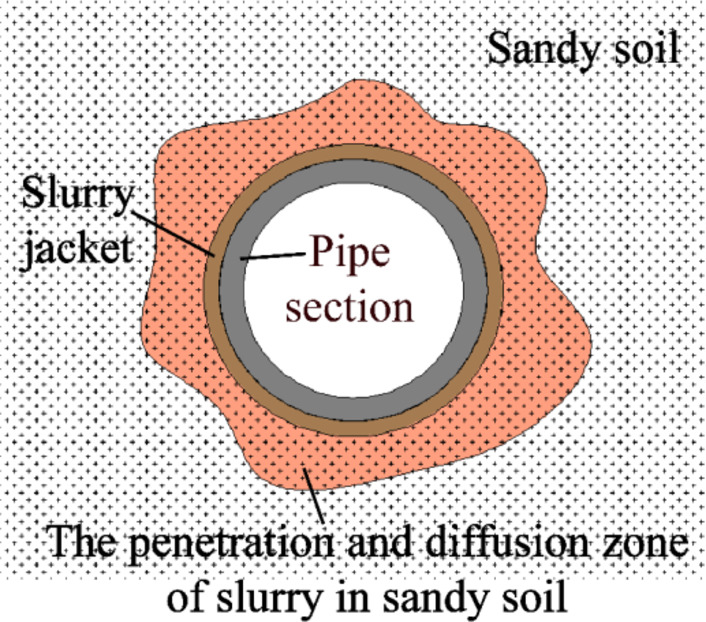
Diagram of slurry jacket state around the pipe section.
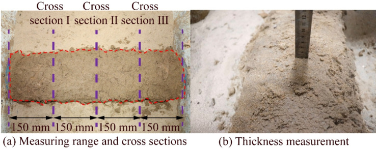
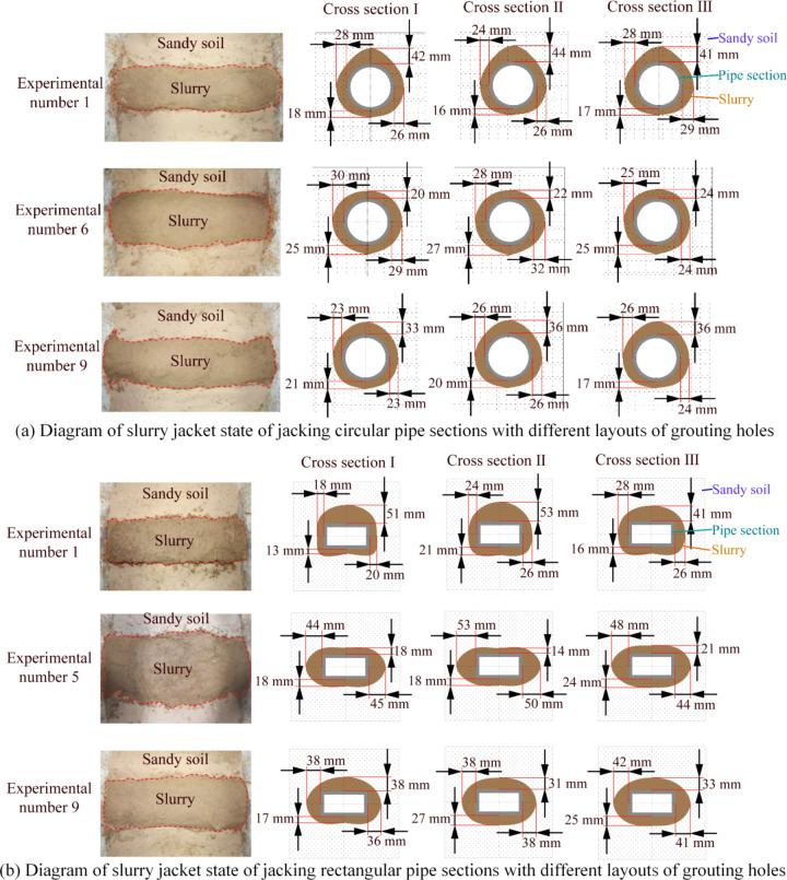
As previously mentioned, the layout of grouting holes is the main factor affecting pipe-soil frictional resistance of jacking circular and rectangular pipe sections under grouting conditions, and it is also the main factor determining the state of slurry jacket. To facilitate the observation of the slurry jacket state with different layout of grouting holes, the experimental groups with the smallest pipe-soil frictional resistance in the single grouting hole, double grouting holes and triple grouting holes in the orthogonal experiment are selected, i.e. the experimental number of jacking circular pipe section is 1, 6 and 9, and the experimental number of jacking rectangular pipe section is 1, 5, 9. The pipe section placed in the geotechnical box is equally divided into four parts, the length of each part is 150 mm, so three cross sections can be generated on the 600 mm long pipe section, i.e. cross section I, cross section II and cross section III. The sandy soil layer at the top of pipe sections is dug out, and the penetration and diffusion distance of slurry at the three cross sections of pipe section placed in the geotechnical box and the four points on the top, bottom, left and right of pipe sections are measured respectively, to obtain the slurry jacket state under different layout of grouting holes. The diagram of measuring method of the penetration and diffusion range of grouting slurry is shown in Fig. 12.
Fig. 12.
Diagram of measuring method of the penetration and diffusion range of grouting slurry.
The slurry jacket states of jacking circular and rectangular pipe sections with different layout of grouting holes are shown in Fig. 13. Among them, the part in the red dotted line is the area of grouting slurry penetration and diffusion, and the right side is the measurement results of the slurry permeation distance of each cross section. It can be clearly found that the diffusion state of slurry in the dry sandy soil is good, and the slurry is completely covered on the outer wall surface of pipe sections. In each group of experiments, the slurry diffusion distance of the three measured cross sections is small, the diffusion is more uniform, and there is no obvious slurry missing area. Comparing the slurry jacket states formed by the single grouting hole, double grouting holes and triple grouting holes, it can be found that no matter the circular or rectangular pipe sections are jacked forward, the slurry diffusion states formed by the layout of single grouting hole are thicker on the upper part and thinner on both sides and bottom, which indicates that if there is only a single grouting hole on the upper part of pipe sections, the slurry grouting amount and grouting pressure on the upper part of pipe sections are larger, and the slurry is easy to accumulate at the grouting hole and permeate to the sandy soil layer above the pipe sections. It is more difficult to flow around the pipe sections, and this phenomenon is more obvious when the rectangular pipe section is jacked forward. Moreover, the slurry diffusion states formed by the layout of double grouting holes are obviously different in the experimental conditions of jacking circular and rectangular pipe sections. For the circular pipe section, because its outer wall surface is arc surface, compared with the rectangular pipe section without right angle turning surface, the slurry can easily flow through the outer wall of circular pipe section under the action of self-weight stress, and the slurry can spread evenly around the circular pipe section, so it is easier to form a slurry jacket with uniform thickness on the outer wall of circular pipe section. However, for rectangular pipe section, the slurry diffusion characteristics are thicker on both sides and thinner on the upper and lower parts. Most of the slurry injected from the two grouting holes on both sides of the rectangular pipe section permeates and diffuses into the sandy soil layer on both sides of the rectangular pipe section, but it is difficult to flow to the upper and lower parts of rectangular pipe section, especially for the upper part. In addition, the slurry diffusion is relatively more uniform when the circular and rectangular pipe sections with the layout of triple grouting holes are jacked in dry sandy soil. The layout of triple grouting holes has more grouting points than the single grouting hole and double grouting holes, it brings together the advantages of single grouting hole and double grouting holes, and its layout is more reasonable, resulting in the grouting slurry can be better dispersed around the outer wall of pipe sections, and the formed slurry jacket is more uniform and complete. Thus, the pipe-soil frictional resistance is generally lower when the pipe sections with the layout of triple grouting holes are jacked in the dry sandy soil.
Fig. 13.
Diagram of slurry jacket states of jacking circular and rectangular pipe sections with different layout of grouting holes.
Based on the above orthogonal experiment results and the analysis of the slurry jacket states, the following suggestions can be put forward for the structure of grouting holes in pipe sections for grouting slurry to reduce pipe-soil frictional resistance method during trenchless pipe jacking construction: Reasonable and uniform layout of grouting holes in different shapes of pipe sections is very necessary to reduce the pipe-soil frictional resistance, especially for the rectangular pipe section with large turning surfaces in each plane, it is more necessary to reasonably and evenly layout of grouting holes in each plane. Meanwhile, on the premise of ensuring the strength of pipe sections, the spacing between adjacent grouting holes S and the deflection angle of grouting holes α should be reduced reasonably to ensure the formation of uniform and high-quality slurry jacket around the outer wall of pipe sections, to effectively reduce the pipe-soil frictional resistance.
Conclusion
Many engineering practices and scientific research have shown that pipe-soil frictional resistance is the key to ensure the smooth implementation of trenchless pipe jacking construction. It is an effective measure to reduce the pipe-soil frictional resistance by grouting lubricating slurry into the annular gap between the outer wall of pipe section and formation to form slurry jacket. Herein, the structures of grouting holes arranged on circular and rectangular pipe sections are optimized by comprehensive use of laboratory experiments, orthogonal experimental design principles, range analysis, variance analysis, etc., which can provide certain references for subsequent pipe jacking engineering practice and relevant scientific research. Consequently, the following conclusions can be drawn:
Several major defects of the original multifunctional experimental apparatus are analyzed, and the corresponding improved methods are put forward to build the improved multifunctional experimental apparatus with more perfect functions. The improved multifunctional experimental apparatus can not only effectively improve the experimental test efficiency, reduce the labor intensity of the experimenters, improve the sealing on both sides of geotechnical box and reduce the leakage of sandy soil, and improve the stability of the variable frequency motor and guide sheaves to increase the test accuracy of pipe-soil frictional resistance. In addition, the newly added grouting module can also meet the requirements of experimental test in the formation process of slurry jacket and its lubricating and reducing friction characteristics under grouting conditions, and effectively expand the function of the experimental apparatus.
The layout of grouting holes, the spacing between adjacent grouting holes S, and the deflection angle of grouting holes α are three key factors affecting the structure and performance of grouting holes. Among them, for circular and rectangular pipe sections, the pipe-soil frictional resistances increase with the increase of the spacing between adjacent grouting holes S and the deflection angle of grouting holes α. Moreover, the layout of grouting holes has the greatest influence on pipe-soil frictional resistance. For jacking circular pipe section in sandy soil, when the circular pipe section with single grouting hole shows the greatest pipe-soil frictional resistance, followed by the double grouting holes, and the triple grouting holes shows the least. For jacking rectangular pipe section in sandy soil, when the rectangular pipe section with double grouting holes shows the greatest pipe-soil frictional resistance, followed by the single grouting hole, and the triple grouting holes shows the least. In addition, the layout of grouting holes directly affects the formation of slurry jacket, because the rectangular pipe section has the structural characteristics of mutual vertical planes, the state of slurry jacket formed in general is not as good as that of the circular Sect.
The optimal structural parameters of grouting holes in circular and rectangular pipe sections are the same as follows: the layout is triple grouting holes, the spacing between adjacent grouting holes S is 417 mm, and the deflection angle of grouting holes α is 40°. For the trenchless pipe jacking construction practice, to ensure the uniform and high-quality formation of slurry jacket around the pipe sections, resulting in enhancing the reduction performance of pipe-soil frictional resistance by grouting lubricating slurry, the multiple grouting holes should be arranged uniformly around the pipe sections as far as possible, especially for the rectangular pipe section, grouting holes should be reasonably arranged in each plane. At the same time, on the premise of ensuring the strength of pipe sections, the spacing between adjacent grouting holes S and the deflection angle of grouting holes α should be reduced reasonably.
Acknowledgements
We would like to express our gratitude to the anonymous reviewers for their constructive comments and suggestions. This research was supported by the National Natural Science Foundation of China (Grant No. 42172348); the Hebei Provincial Natural Science Foundation of China (Grant No. E2023210022); the Opening Fund of State Key Laboratory of Geohazard Prevention and Geoenvironment Protection (Grant No. SKLGP2021K026); the Open Research Fund Program of Engineering Research Center of Geothermal Resources Development Technology and Equipment, Ministry of Education, Jilin University (Grant No. 22014); the University Student Innovation and Entrepreneurship Program Training Program of Shijiazhuang Tiedao University (Grant No. 202310107288, No. 202410107288, No. 202410107306).
Author contributions
J.W.: Conceptualization, Methodology, Writing-Review and Editing, Supervision, Re-sources, Funding acquisition. Y.C: Investigation, Data Collection and Curation. T.X.: Inves-tigation, Data Collection and Curation, Analysis, Writing-Review and Editing. M.C.: Data Collection and Curation. H.L.: Data Collection and Curation. W.H.: Data Collection and Curation. D.Y.: Data Collection and Curation. J.L.: Data Collection and Curation. Z.Z.: Data Collection and Curation.
Data availability
Data is provided within the manuscript.
Declarations
Competing interests
The authors declare no competing interests.
Footnotes
Publisher’s note
Springer Nature remains neutral with regard to jurisdictional claims in published maps and institutional affiliations.
References
- 1.Wen, J. W., Zhang, P. S. & Xiang, T. Comparative research on the pipe-soil frictional resistances of circular and rectangular pipe sections during trenchless pipe jacking. PLOS ONE. 19(2), e0297537 (2024). [DOI] [PMC free article] [PubMed] [Google Scholar]
- 2.Ma, P. et al. Transition of the pipe jacking technology in Japan and investigation of its application status. Tunn. Undergr. Space Technol.139, 105212 (2023). [Google Scholar]
- 3.Lu, H. F., Matthews, J. & Iseley, T. How does trenchless technology make pipeline construction greener? A comprehensive carbon footprint and energy consumption analysis. J. Clean. Prod.261, 121215 (2020). [Google Scholar]
- 4.Deng, M. L. et al. Surface settlement law of double-hole pipe-jacking tunnel undercrossing expressway. Sci. Rep.13, 19286 (2023). [DOI] [PMC free article] [PubMed] [Google Scholar]
- 5.Kong, C., Guan, G. Q., Gu, S., Zhou, Z. Y. & Wang, H. Y. Frictional resistance calculation and jacking force prediction of rectangular pipe jacking. Sci. Rep.13, 14992 (2023). [DOI] [PMC free article] [PubMed] [Google Scholar]
- 6.Wen, K., Zeng, W., Shimada, H., Sasaoka, T. & Hamanaka, A. Numerical and theoretical study on the jacking force prediction of slurry pipe jacking traversing frozen ground. Tunn. Undergr. Space Technol.115, 104076 (2021). [Google Scholar]
- 7.Wen, K., Shimada, H., Zeng, W., Sasaoka, T. & Qian, D. Y. Frictional analysis of pipe-slurry-soil interaction and jacking force prediction of rectangular pipe jacking. Eur. J. Environ. Civil Eng.24(6), 814–832 (2020). [Google Scholar]
- 8.Ji, X. B. et al. A method to estimate the jacking force for pipe jacking in sandy soils. Tunn. Undergr. Space Technol.90, 119–130 (2019). [Google Scholar]
- 9.Liu, W. Z., Tan, J. M., Shi, J. W., Huang, X. J. & Chen W. A method for calculating jacking force of parallel pipes considering soil arching effect and pipe-slurry-soil interaction. Comput. Geotech.173, 106528 (2024). [Google Scholar]
- 10.Liu, J. M., Wang, X. Z., Cheng, H. & Fan, H. X. Orthogonal design and microstructure mechanism analysis of novel bentonite polymer slurry in pipe jacking. Polymers15(6), 1461 (2023). [DOI] [PMC free article] [PubMed] [Google Scholar]
- 11.Cui, H., Kou, L., Xiong, Z. H. & Zhao, J. J. Detection and analysis of slurry jacket for pipe jacking construction in soft ground. J. Civil Struct. Health Monit.13(2–3), 309–317 (2022). [Google Scholar]
- 12.Liu, S. et al. Formulation optimization and performance analysis of the thixotropic slurry for large-section rectangular pipe jacking in anhydrous sand. Constr. Build. Mater.357, 129380 (2022). [Google Scholar]
- 13.Ye, Y. C., Peng, L. M., Yang, W. C., Zou, Y. & Cao, C. Y. Calculation of friction force for slurry pipe jacking considering soil-slurry-pipe interaction. Adv. Civil Eng.. 6594306 (2020). (2020).
- 14.Ye, Y. C. et al. Prediction of friction resistance for slurry pipe jacking. Appl. Sciences-Basel. 10(1), 207 (2020). [Google Scholar]
- 15.Wang, C., Li, D. & Zhang, C. L. Key points and current research status of pipe jacking technology. Urbanism Archit.18(11), 139–144 (2021). (in Chinese). [Google Scholar]
- 16.Yang, X., Liu, Y. & Yang, C. Research on the slurry for long-distance large-diameter pipe jacking in expansive soil. Adv. Civil Eng. 9040471 (2018). (2018).
- 17.Namli, M. & Guler, E. Effect of bentonite slurry pressure on interface friction of pipe jacking. J. Pipeline Syst. Eng. Pract.8(2), 04016016 (2017). [Google Scholar]
- 18.Zhou, S., Wang, Y. Y. & Huang, X. C. Experimental study on the effect of injecting slurry inside a jacking pipe tunnel in silt stratum. Tunn. Undergr. Space Technol.24(4), 466–471 (2009). [Google Scholar]
- 19.Ma, P. et al. A new method for predicting the friction resistance in rectangular pipe-jacking. Tunn. Undergr. Space Technol.123, 104338 (2022). [Google Scholar]
- 20.Yang, H. J., Rong, L. & Xu, H. C. Application of drag reduction technology to extra-large cross-sectional rectangular pipe jacking: case study of tunnel crossing underneath Zhongzhou road in Zhengzhou. Tunn. Constr.36(4), 458–464 (2016). (in Chinese). [Google Scholar]
Associated Data
This section collects any data citations, data availability statements, or supplementary materials included in this article.
Data Availability Statement
Data is provided within the manuscript.


