

Abstract
In coal mining operations, it is often challenging to control the deformation of the roadway in front of the working face. The excessive stress from the surrounding rock of the working face and the difficulties in caving the goaf roof have led to a prominent factor that hinders safe and efficient production in coal mines. For this reason, a mechanical model of the stress field in the advance roadway of the working face is established, and the stress evolution law of the surrounding rock before and after cutting the roof of the roadway is analyzed. Key parameters such as cutting depth, cutting angle, and hole spacing are determined through theoretical calculation, numerical simulation with 3DEC numerical software, and field testing. A kind of roof cutting and pressure relief techniques (TCPAF) for enhanced roadway safeguarding in advance mining face is proposed, and its effectiveness is verified through field testing. The results indicate that the stress on the low-stress side of the leading roadway remains slightly increased, while on the high-stress side, stress decreases significantly, optimizing the stress environment of the surrounding rock. In addition, the research results provide a scientific basis for similar conditions of roadway deformation.
Keywords: Roof pressure relief, Surrounding rock stress evolution, Numerical simulation, Mine pressure behavior, Advance stress of mining face
Subject terms: Coal, Civil engineering
Introduction
Coal is the main energy source in China and holds a dominant position in the primary energy structure1. As the energy revolution continues to develop, the safe and efficient mining of coal resources has become of paramount importance.In the process of mine production, the deformation and failure of the surrounding rock on both sides of the roadway are prone to occur under the influence of the dynamic pressure of the advanced roadway of mining face. This is influenced by the high ground stress in depth and the mining-induced stress, leading to a significant increase in displacement of the roof and sides of the roadway, resulting in large deformation of the surrounding rock, exhibiting a typical phenomenon of large deformation and strong rheological phenomenon. The existing supporting methods cannot effectively control the deformation of the surrounding rock of the roadway, reducing the economic benefit of mining, threatening the safety of mining production, and restricting safe and efficient mining operations.Therefore, it is particularly important to study the deformation mechanism of the surrounding rock and develop corresponding surrounding rock control technology. In order to ensure safe and efficient coal mining, technology such as roof cutting and pressure relief has been widely used in recent years. This can reduce the pressure on the roof, which breaks through hard roofs, relieves mining pressure, recovers coal resources and has been widely used in various mining areas under different geological conditions.
roof cutting pressure relief technology has advantages in breaking hard roof, relieving mining pressure, recovering coal resources and has been widely used in various mining areas under different geological conditions2–4. In recent years, experts and scholars have done a lot of research on the deformation mechanism and control technology of surrounding rock by cutting and relieving pressure. In 2008, Professor He Manchao put forward the mining technology of cutting the roof and unloading pressure without coal pillar, which is called 110 construction method5. Xue Weifeng6 built a mechanical model of stope floor under periodic pressure, and theoretically calculated the failure pattern of postharvest floor. Yuan Chaofeng3 established a mechanical model of roadway retaining roof and determined the variation law of tensile stress of unpenetrated surface under different cutting depth and cutting Angle.Gao Yubing7 analyzed the evolution process and mechanical action mechanism of surrounding rock structure of the roof-cutting roadway based on the mechanical mechanism of roof-cutting roadway without coal pillar. Ma Xingen8 established corresponding mechanical models for different sections of roadway and obtained the deformation rule of roadway roof. The key parameters of roof cutting and pressure relief technology include roof cutting depth, roof cutting Angle and roof cutting borehole spacing. Through a large number of engineering events, Sun Xiaoming9 studied the key parameter determination method of thin coal seam roof-cutting pressure relief technology from the perspective of fracture mechanics.Xu Xiaoding10 based on fractal and tie rod damage theory achievedA new calculation model of blasting damage degree. Liu Xiaoqiang11 achieved ideal slit cutting and lane retention effects through field experiments. As for the research on cutting roof depth, the current main theoretical determination method is based on the rock mass dilatation theory, that is, the depth of the cut rock layer is equal to the thickness of the rock layer that can effectively support the overlying rock layer after the completely filled goaf is crushed12. The research of Guo Zhibiao13 on the cutting depth of thin coal seam shows that whether the direct roof can be cut off smoothly depends on the tensile stress acting on the unpenetrating surface of the cutting roof. Yuan Chaofeng14 obtained the relationship between the tensile stress of the unpenetrated surface and the cutting depth and cutting Angle of the coal seam with thin direct roof and large mining depth, so as to determine the cutting Angle. In terms of drilling, the larger the diameter and spacing of drilling holes, the greater the degree of plastic zone development around drilling holes15. For drilling, larger diameters and spacing for drilling holes lead to greater development of plastic zones around drilling holes. For different working conditions, various theories must be combined with field conditions to obtain reasonable cutting depth, cutting angle, and drilling spacing. Therefore, selecting reasonable roof cutting parameters should be based on actual engineering and technical conditions to achieve ideal roof cutting effects.
A large number of scholars have conducted a lot of research on solving problems related to thick and hard overhanging roofs and determining reasonable cutting parameters from theory to practice. This has provided reference and ideas for effectively solving problems related to hard leading stress in mining direction roadway surrounding rock, especially for gob-side entry retaining cutting technology .However, there are few reports on leading stress control technology for roadway surrounding rock in front of the mining direction of the working face, especially regarding failure mechanisms of both sides of the roadway surrounding rock, stress change law analysis, and key parameter design for cutting and protecting roadways of advance working face.Therefore, this paper establishes a mechanical model for stress field distribution in advance working face and carries out mechanical analysis to obtain stress variation laws for both sides of roadway surrounding rock in advance workings. The problem of uneven stress between sides of roadway and poor stability of one-side roadway is solved. Furthermore, we propose a technology named adcance working face roof-cutting(AWFT) to protect the roadway by reducing adcance stress. By means of comprehensive theoretical analysis, numerical simulation, and field test, key parameters for roof cutting and pressure relieving roadway protection at Pingdingshan sixth mine are determined. The roof cutting and pressure relieving scheme that meets actual conditions at the mine is developed, which ultimately achieves ideal pressure relieving effects through industrial application. This provides scientific basis and experience reference for controlling deformation of roadway surrounding rock under similar conditions.
Engineering overview
Engineering geological conditions
Pingdingshan Sixth Mine is located in Pingdingshan City, Henan Province. Overall, the three-level pentane belt hill is located in the coal roof of pent9-10, approximately 20–24 m away from the vertical depth of pent9-10 coal (up to 30 m in some areas). The strike length of working face 22,190 is 676 m, the width is 90.9 m, with an average thickness of coal seam of 2.45 m, and a dip angle of 8° to 17°. The coal seam strikes 98° to 107°. The roof thickness of the coal seam consists of 5.4 m of sandy mudstone and 4.1 m of fine sandstone. The relationship between the position of working face 22,190 and the rock column diagram is shown in Fig. 1.
Fig. 1.

Working position relationship of 22,190, rock column diagram.
Engineering problems
When exploring the 22,190 face, as illustrated in Fig. 2, the roadway in the front of mining face is also influenced by mining activities, leading to stress concentration on the surrounding rock on the both sides of the advance roadway of working face. With the continuous forward mining of the working face, the surrounding rock in a high-stress environment within a certain range on both sides of the roadway will be deformed and destroyed. When the working face advances to the vicinity of the stop-mining line, deformation and failure become more severe16. In some cases, this can even lead to large-scale instability and collapse of the roadway, posing a serious threat to safe and efficient coal mining operations17. Therefore, it is essential to analyze the deformation and failure mechanism of roadway surrounding rock in such situations, and then determine a reasonable solution to protect safe and efficient coal miningoperations.and then determine a reasonable solution to protect safe and efficient coal miningoperations.
Fig. 2.

Roadway layout and surrounding rock failure.
Overlying strata movement and mine pressure manifestation
During advancing of the miningface, the main roof fractures to form an “X-O” type collapse. As shown in Fig. 3, the hard overburden above the working face breaks to form a “overhanging beam” configuration with two curved triangular masses at each end and a larger cantilever mass supported by three fixed anchors and a simple support at the front end of the retreat roadway. Under the influence of this “overhanging beam”, the surrounding rock on both sides of the working face advance roadway is affected by uneven forces, and the stress on one side (right side) is excessive, thus affecting the stability of the surrounding rock in the roadway. At the same time, this will cause the support in the withdrawal roadway to become unstable, so blasting is used to cut the roof of the withdrawal roadway to reduce the concentrated surrounding rock stress in the advance roadway of working face and protect its stability.
Fig. 3.

Distribution of leading stress during mining of the working face.
Mechanism of roof cutting pressure relief of advance working face
Severe disturbance results in excessive pressure of surrounding rock on the high stress side of the advance roadway. Therefore, a mechanical model of stress distribution in advance of the working face was established for calculation. The mechanical model is shown in Fig. 4.
Fig. 4.

Stress analysis diagram of roof.
Simplify the three-dimensional coordinate system to the two-dimensional coordinate system, from 
| 1 |
The rock loads on the both sides of the working face advance roadway are simplified into F1 and F2, which are approximately considered to be the surrounding rock stress of the two sides of the working face advance roadway, and the solution and analysis are carried out, namely:
 |
2 |
| 3 |
From  :
:
| 4 |
Other parameters in Eq. (4) are further analyzed in detail:
①Overlying rock action load q3
 |
5 |
Where, K is the load transfer coefficient18;  is the average unit weight of the load layer, kN/m3.
 |
6 |
Where λ3 is the lateral stress coefficient of the basic overburden.
Simultaneous formula (5) and (6) are obtained:
 |
7 |
②The weight of the overhanging beam on the main roof and part of the overlying strata is PG
 |
8 |
In the formula, h2 is the thickness of the overhanging beam of the basic roof and part of the overlying strata, m;  is the unit weight of the overhanging beam on the main roof and part of the overlying strata, kN/m3.
③Immedicate roof load q0
Since the rock layer is generally small in thickness and close to the roadway support structure, the load transfer effect is not considered.
 |
9 |
Where, h1 is the Immedicate roof thickness, m;  is the Immedicate roof unit weight, kN/m3.
④ FZ is the supporting force provided by collapse gangue, and xz is the position of supporting force.
⑤ X1, X2 are the force acting distance of the two sides of the advance roadway at the simplified rear working face respectively.
By combining Eqs. (1) and (4) and substituting them into Eqs. (7), (8) and (9), the forces F1 and F2 of the both sides of the working face advance roadway can be obtained as:
| 10 |
| 11 |
The reduction of overlying load and overhanging beam dead weight can effectively improve the loading condition of the advance roadway. collapse gangue from the roof, serves as a support for the overhanging beam through blasting and cutting roof. To increase the supporting force, the filling degree of collapse gangue can be increased by adjusting the cutting depth, thus improving the supporting force of the filling on the overhanging beam. roof cutting directly affects the length of the overhanging beam. As shown in Eqs. (10) and (11), roof cutting is not simply a positive correlation effect on the stress of surrounding rock on both sides of the leading roadway at the working face, and continue to analyze Eqs. (10) and (11) further.
On account of  ,Therefore, in the analysis of the change of the force F1 and F2 on the two sides of the working face advance roadway, Defining main Influencing Parameters
  and
and  , continue to analyze it:
Let  be the argument x, The principal coefficient functions y1 and y2 are defined as:
 |
12 |
 |
13 |
X2 > X1, as shown in Fig. 5.
Fig. 5.
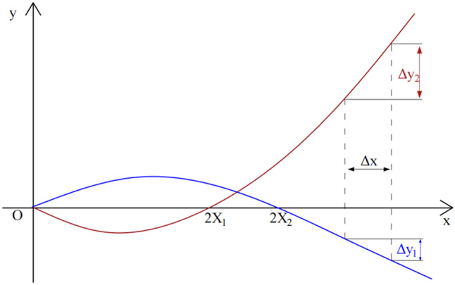
Influence agent function diagram.
As can be seen from the analysis of Fig. 5,When a change in x occurs, y1 andy2 have opposite directions, and the absolute value of y1 is less than y2, which represents when the depth decreases, the force F1 on the left side of the working face advance roadway increases slightly while the force F2 on the right side decreases significantly. From the above analysis, it can be seen that roof-cutting can balance the stress on the left and right sides of the roadway, significantly reducing the stress on the surrounding rock on the right side which has the most serious influence on the stress and deformation of the roadway. Therefore, a technology of adcance working face roof-cutting(AWFT) is proposed to improve the stress on the surrounding rock of the advance roadway.
In summary, as can be observed from the above analysis, adcance working face roof-cutting(AWFT) can effectively balance the stress on both sides of the roadway, thereby significantly reducing the stress on surrounding rock on the right side and greatly improving the stability of the advance roadway. Therefore, it is recommended to adopt this technology in advance working face construction.
Key parameters of TCPAF
Roof-cutting key parameters include roof-cutting depth and roof-cutting angle. When the cutting depth is altered, the collapse gangue of the roof plays a role of lateral support to the overhanging beam and affects the dead weight of the overhanging beam. When the cutting depth advances to the thick hard rock layer, due to its strong strength and thickness, the overhanging block has already been fractured under mining-induced stress, and completely cutting off the layer is conducive to enhancing roadway protection effects. However, at the same time, too high a cutting depth will increase the weight of the overhanging beam itself, which also weakens roadway protection effects. Therefore, the determination of roof-cutting depth should be based on rock mass swelling theory and the distribution of rock strata. If the roof-cutting angle is too large, the weight of the overhanging beam will increase. Conversely, if the roof-cutting angle is too small, the collapse gangue cannot support the overhanging beam effectively.
From the above analysis, it can be seen that the selection of cutting depth and angle is crucial to roof-cutting effect and roadway protection. These parameters should be comprehensively determined through theoretical calculation and numerical simulation.
Theoretical calculation of key parameters of roof-cutting
Theoretical analysis of roof-cutting depth
According to the rock mass dilatation theory Hq is:
 |
14 |
Where: Hq is the cutting depth, m; M is the mining depth, m; ΔH1 is the roof subsidence, m; ΔH2 is the volume of floor heave, m; K is the weighted average collapse coefficient of roof rock mass, and ΔH1 can be calculated according to the beam theory of elastic foundation19.
Among them,
 |
15 |
Where is the crushing coefficient of the roof stratum of the i layer; is the thickness of Layer i roof rock, m.
According to formula (14), the working face of Pingdingshan Sixth Mine 22,190 working face can be concluded that when the cutting depth is 13.2 m, the collapse gangue is sufficient to fill the goaf. At this time, the rock layer is 3.2 m away from being completely cut off. During the mining process of the working face, the overlying rock stratum is fractured due to the influence of mining. The mining disturbance will form a critical block of fracture, that is, a overhanging beam structure is formed above the goaf to increase the load on the roadway, so the layer is completely cut off, and the roof-cutting depth is 16.4 m.
Theoretical analysis of roof-cutting angle
For the beam formed by grip structure for rock blocks, it is also known as a “bond-beam”. Based on the bond-beam theory and the S-R stability principle of surrounding rock structure20,19, an equilibrium mechanical model is established for the grip structure for rock blocks, as shown in Fig. 6, that is based on the fracture characteristics of rock block A and rock block B.
Fig. 6.
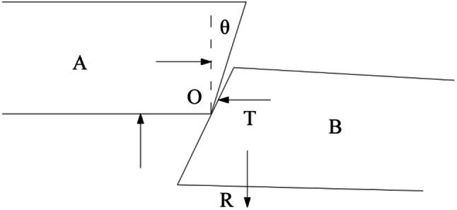
Equilibrium mechanical model of occluding point of overburden broken rock.
Considering the fracture of overlying rock, the fracture surface will produce a certain Angle with the vertical direction, and the mechanical relationship of the bite point of two adjacent rock blocks is shown in Fig. 6. Force analysis is carried out on the hinge point O, and the relationship and equilibrium conditions of the mutual force are as follows22:
| 16 |
To wit:
| 17 |
The equilibrium condition is derived as follows:
 |
18 |
among:
 |
19 |
 |
20 |
By substituting Eqs. (19) and (20) into Eq. (18), it can be obtained that the rock slip instability condition is:
| 21 |
Where, θ is the roof-cutting angle, (°); Δs is the subsidence of block B, m; L is the span, m; φ is the basic internal friction Angle at the roof, (°); T is the horizontal force of rock block, kN; hE is the mining thickness of coal seam, m. According to the geological conditions of the 22,190 working face of Pingdingshan Sixth Mine, φ ≥ 5.74° can be obtained by substituting Δs =0.8 m, φ = 36°, T =4.8kN, and hE =2.2 m into Eq. (25).
Due to the selection of the roof-cutting depth, collapse gangue has completely filled the goaf, so at this point, the roof-cutting angle will affect both the weight of the roof overhanging beam and the lateral supporting force of the collapse debris on the overhanging beam. As the cutting angle increases, the additional dead weight of the overhanging beam will increase correspondingly, but the supporting effect can be strengthened by increasing the angle of the supporting surface of the collapse gangue. A too small roof-cutting angle will also lead to difficulties in drilling charges and sealing holes, and collapse gangue cannot effectively support the overhanging beam laterally. In order to obtain an efficient roof-cutting angle and depth, it is necessary to conduct numerical simulation to further verify the reasonable roof-cutting angle and depth.
Optimization and determination of roof cutting parameters
Through the above theoretical analysis, the optimal cutting depth and cutting angle range are determined. In this section, based on the geological conditions of the 22,190 working face and the theoretical analysis results, the optimal roof-cutting depth and roof-cutting angle for special geological conditions will be simulated and determined.
Model establishment and simulation scheme design
In order to study the optimal effect of roof-cutting and protecting the roadway at different cutting depths and angles, the numerical calculation model as shown in Fig. 7 was established by using discrete element software 3DEC, with the model size of 150 m×140 × 55 m.5 vertical stress detection points are arranged at 1 m interval on the left side of the study roadway, and 8 vertical stress detection points at 1 m interval on the right side of the study roadway to observe the surrounding rock detection of the both sides of the study roadway.
Fig. 7.

3DEC numerical model.
The upper boundary condition of the model adopts stress boundary condition, which can be simplified as uniform load. The bottom displacement is set to a fixed boundary, the roof of the model is set to a stress boundary, and the side displacement is set to a free boundary. The rock block adopts the molar Coulomb model and the joint adopts the Coulomb slip model. The mechanical parameters of coal and rock are shown in Table 1. In order to observe the basic roof caving situation and its influence on the stability of the working face over the front surrounding rock, the pre-cracking cracks in the field are simulated by cutting cracks with different depth.
Table 1.
Mechanical parameters of coal and rock mass.
| Lithology | Thick-ness/m | Bulk modu- lus/Gpa |
Shear modu- lus/Gpa |
Cohesion /Mpa |
Friction angle/° |
Tensile strength/Mpa |
|---|---|---|---|---|---|---|
| Sandy mudstone | 11.2 | 2.56 | 2.36 | 2.16 | 36 | 0.58 |
| Medium-grained sandstone | 9.3 | 2.89 | 2.54 | 3.2 | 40.9 | 3.7 |
| Sandy mudstone | 9.7 | 2.56 | 2.36 | 2.16 | 36 | 0.58 |
| Fine-grained sandstone | 4.4 | 21.01 | 13.52 | 3.2 | 42 | 1.29 |
| Sandy mudstone | 7.2 | 2.56 | 2.36 | 2.16 | 36 | 0.58 |
| Fine-grained sandstone | 4.1 | 21.01 | 13.52 | 3.2 | 42 | 1.29 |
| Sandy mudstone | 5.1 | 2.56 | 2.36 | 2.16 | 36 | 0.58 |
| Coal | 2.15 | 4.91 | 2.01 | 1.25 | 32 | 0.15 |
In order to effectively analyze the influence of cutting roof depth and cutting angle on the cutting roof protection effect, the selected values of simulation parameters were determined based on the theoretical calculation results of the third part, and the design scheme of cutting roof parameters was established, as shown in Table 2. The specific content is as follows: First, the cutting roof angle is fixed at 15°, and the cutting roof depth is taken as the variable. 5 groups of control experiments are set, and the cutting roof depths of each group are 0 m, 10 m, 13 m, 16 m, 19 m respectively. Secondly, the fixed roof cutting depth was the optimal value of the first group, and three groups of control experiments were set with the roof cutting angle as the variable, and the roof cutting angle of each group was 10°, 15° and 20°.
Table 2.
Design scheme of cutting roof parameters.
| Group number | Parameter value | Group number | Parameter value | ||
|---|---|---|---|---|---|
| Cutting depth | 1 | 0 m | Cutting angle | 1 | 10° |
| 2 | 10 m | 2 | 15° | ||
| 3 | 13 m | 3 | 20° | ||
| 4 | 16 m | ||||
| 5 | 19 m |
Stress analysis of surrounding rock on both sides of advance roadway under different cutting depth
In order to analyze the influence law of cutting roof depth on the stress of both sides of roadway, statistical analysis was carried out on all detection conditions, the stress distribution patterns and the stress comparison diagram of detection points with different cutting roof depth was obtained, as shown in Fig. 8.
Fig. 8.

Numerical simulation results of cutting height. (a) The stress distribution patterns on two sides of roadway with different cutting depth (b) Stress diagram of surrounding rock monitoring points on two sides of roadway with different cutting depth.
The analysis of the surrounding rock force of the two sides of the roadway under different cutting depths reveals the following facts:
(1) Different cutting heights resulted in a decrease in vertical stress on the right side of the roadway, with the most significant reduction occurring at a cutting height of 16 m. The vertical stress on the left side exhibited a slight increase after cutting, but the maximum vertical stress on the left side did not exceed that on the right side, consistent with the conclusions from the mechanical analysis of stress variation in the surrounding rock discussed in Chap. 3.
(2) When the roof cutting depth is set at 10 m, as seen in Chap. 4 calculations, it can be observed that the collapse gangue has not completely filled the goaf at this time, so the roof cutting effect is not significant compared to cases without roof cutting. The average stress on the left side of the roadway remains essentially unchanged with roof cutting while the maximum stress on the right side of the roadway decreases slightly. (3)When the roof cutting depth is set at 13 m, at this time, collapse gangue has completely filled the goaf, and collapse gangue provides good lateral support for the overhanging beam. However, there is still 3 m before the sandy mudstone layer is completely cut off, and the uncut hard part of the layer is difficult to collapse, so the effect remains suboptimal compared to a cutting roof depth of 16 m.
(4) At a cutting depth of 16 m, the maximum stress on the right side of the roadway experiences the greatest decrease in surrounding rock stress. Although the stress on the surrounding rock on the left side of the roadway increases, the maximum stress on the left side remains lower than that on the right side. The stress state of the surrounding rock on both sides of the roadway is tending towards symmetry, greatly improving the stress state of both sides and achieving optimal cutting effect.
(5) When the cutting roof depth is increased to 19 m, this exceeds a third layer of sandy mudstone, and increasing the cutting roof depth increases the weight of the overhanging beam. Compared to a cutting depth of 16 m, it can be seen that higher cutting roof depths are not necessarily optimal.
Stress analysis of surrounding rock on two sides of advance roadway under different cutting angles
In order to analyze the influence law of the roof cutting Angle on the stress of the two sides of the roadway, statistical analysis was carried out on all detection conditions, and the stress comparison diagram of detection points at different roof cutting angles was obtained, as shown in Fig. 9.
Fig. 9.

Numerical simulation results of cutting angles. (a) The stress distribution patterns on two sides of roadway with different cutting angles. (b) Stress diagram of surrounding rock monitoring points on two sides of roadway with different cutting angles.
The comparative analysis of the surrounding rock diagrams of the two sides of the roadway under different cutting angles reveals the following:
(1)When compared to the 15° cutting angle, the lateral support effect of collapsed overburden on the overhanging beam is weakened due to the smaller 10° cutting angle, leading to slightly higher stress in the surrounding rock of the two sides of the roadway.
(2)When compared to 15°, the increase in the 20° cutting angle results in an increase in the weight of the overhanging beam, leading to a slight increase in the surrounding rock stress on the two sides of the roadway. However, the influence of cutting angle on the weight of the overhanging beam is significantly less than that of cutting depth on the weight of the overhanging beam.
(3) Overall, the effect of a 10° cutting angle is similar to that of a 15° cutting angle.
Analysis and discussion
(1)The change of cutting roof depth mainly affects the filling degree of the gob and the thickness of the hanging beam formed after the roof collapse. A reasonable cutting roof depth can not only effectively fill the gob and support the overlying strata, but also make the weight of the short overhanging beam within a certain range, thereby increasing the stability of the working face advance roadway.The selection of cutting depth has a significant impact on the filling degree of the goaf and the thickness of the hanging arm beam after the roof collapse. A suitable cutting depth can not only effectively fill the goaf and support the overlying strata, but also ensure that the dead weight of the short overhanging beam remains within a certain range, thereby enhancing the stability of the working face advance roadway.A working condition exists where the third layer of sandy mudstone above the coal seam is thick and hard. When the cutting depth meets the filling condition for collapse gangue but does not cut off the third layer of sandy mudstone, while the broken gangue can fully and effectively support the overlying rock and relieve pressure to a certain extent, it is found that the overhanging beam will still be subjected to great transmission of force in the advance roadway, leading to significant deformation and displacement of the roadway.However, simply increasing the cutting depth may lead to excessive weight of the overhanging beam, and may destroy the hinged balance structure formed by the overburden, which will weaken the effect of roadway protection. In addition, excessive cutting depth may cause excessive blasting charge and difficulty in sealing holes. Therefore, in practical design processes, it is necessary to not only consider whether sufficient collapse gangue is filled in the goaf, but also determine cutting depth based on rock formation thickness and hardness on site.
(2)The change of cutting angle mainly affects the length of the roof overhanging beam and the lateral support of the gangue to the overhanging beam. If the angle at which roof is cut is too small, it may be difficult to charge and seal holes, which may easily result in damage to anchor cable anchorage areas near drilling holes at the roof, and may also reduce the lateral support of the overhanging structure. On the other hand, if the cutting angle is too large, it may increase the weight of the overhanging beam, which is not conducive to maintaining stability in surrounding rock of roadway, but, it is not obviously from the stress analysis of surrounding rock on two sides of advance roadway under different cutting angles.
(3)The combination of theoretical analysis and numerical simulation is a good choice for determining roof cutting depth and angle. Based on theoretical analysis and numerical simulation, key parameters for roof cutting have been determined: roof cutting depth is 16 m and roof cutting angle is 15°. However, at the same time, we should be mindful of actual rock thickness and joint development influencing these two parameters.
Application of TCPAF and field experiment
Determining the distance between drill holes
To design the hole spacing, it is necessary to ensure that the radial cracks generated by adjacent holes are thoroughly connected to form a section to maximize the roof cutting effect. The sum of the damage depth caused by two shaped charge blasting holes should be greater than the hole spacing, which serves as a judgment criterion for designing the hole spacing. Therefore, relevant scholars have proposed an empirical expression for hole spacing23,24:
 |
22 |
Where d is the center distance of adjacent gun holes; r is the radius of drilling, 24 mm; is the pressure measurement coefficient (0.45); po is the primary rock stress, which is 5.7; pbis the peak shock wave pressure of the hole wall of the gun, taking 720Mpa; ko is the initial damage coefficient of rock mass, which is 1.3.σt is the tensile strength of rock mass, which is 1.07Mpa;
  is the attenuation coefficient of explosion stress wave (1.3)
The calculated hole spacing is d ≤ 1140 mm, and the theoretical analysis of blasting spacing cannot fully account for the development of rock joints and the complex boundary conditions of the roof rock in the mining area. This results in a more practical application of a field-based method combined with feedback design using peep technology.
Aiming at the problem of the uncontrollability of the direction of cracks in non-directional blasting, based on the characteristics of rock compressive and tensile failure, this article proposes the use of directional shaped charge blasting technology25. The device is tubular, with shaped holes on both sides26, and has a symmetrical distribution which make the crack will spread along the direction of the hole. It is difficult to form through cracks due to the inconsistency of blasting angles in adjacent blasting holes, therefore, in roof presplitting blasting, interhole charge blasting is carried out, and a non-blasting guide hole is left in the middle, thus solving the problem of difficulty in forming a through surface due to inconsistent blasting crack angles, and ultimately realizing the controllability of the blasting crack.
Dected the cracks in the guide hole, and the expansion of the directional pre-cracks in the hole is detected through borehole detection and imaging, thus evaluating the effect of presplitting blasting and determining the reasonable parameters of shaped charge presplitting blasting. The blasting principle and damage to roadway roof are shown in Fig. 10.
Fig. 10.

Polymerization device and blasting principle.
In order to obtain reasonable hole spacing, three test schemes are designed on site, namely, hole spacing of 1000 mm, 800 mm and 600 mm respectively, that is, the spacing between blasting holes and guide holes is 500 mm, 400 mm and 300 mm to test. The three schemes all adopt the mode of interhole charging and blasting. The depth of the roof cutting hole was 16.4 m, the Angle of the roof cutting hole was 15°, and the diameter of the roof cutting hole was 48 mm. After blasting, the guide holes under three different schemes are probed in the holes, and the crack length in the holes is measured. The drilling and viewing situation is shown in Fig. 11.
Fig. 11.

Borehole peep.
Based on the observation results, when the spacing is 500 mm there are no conspicuous cracks in most observation holes, only a few local cracks, and the average crack rate in holes is 31.1%. When the spacing is reduced to 400 mm, there is no conspicuous crack in the observation hole, and the crack rate in the hole is 73.4%. However, when it is reduced to 300 mm intervals for blasting, the observed hole exhibits a symmetrical distribution and two main cracks that run from the orifice to the bottom of the hole are clearly visible, with a longitudinal crack rate in the hole exceeding 90%. Thus, using the hole spacing of 300 mm (with adjacent blasting hole spacing of 600 mm), can meet the actual field directional precracking requirements.
Field scheme design
On the basis of the analysis of the stress evolution mechanism of the two sides of the roadway and the key technology of advance working face roof-utting, the 22,190 working face of Pingdingshan Coal Mine was selected for field engineering test. Considering the actual construction situation on site, in order to cut off the thick hard roof plate, the depth of the blasting hole was designed to be 16.4 m, with an inclination angle of 75° with the horizontal plane, and a diameter of 48 mm for the breaking hole. Blasting holes were arranged in groups, with each group consisting of 1 blasting hole and 1 guide hole. The spacing between two holes in a group was 300 mm, and the spacing between groups was 600 mm. Both the blasting hole and the guide hole were located on the side of the roof withdrawal roadway. During site construction, the shaped charge tube was installed in the blasting hole. The three-stage emulsion explosive was selected to maximize blasting efficiency. The explosive specification was Φ32mm×400 mm/roll, with each roll containing 300 g of explosive. The outer diameter of the polymer tube was 45 mm, with an inner diameter of 39 mm and a tube length of 2000 mm. A single hole “4 + 4 + 3 + 3 + 3 + 2 + 1” charging structure was adopted to ensure optimal blasting results. The A-A profile design of the blasting hole, as well as the charge construction of the blasting hole and the layout of the combined blasting hole, are shown in Fig. 12.
Fig. 12.

Design of hole layout and charge structure.
Stress monitoring of surrounding rock on both sides of roadway
To verify the effectiveness of TCPAF, the ZKYL-48 flexible detection unit was used to monitor the stress in the coal body on both sides of the studied roadway.The roadway advance face sides are drilled horizontally to a depth of 2.5 m and 4 m respectively. The detection instrument is inserted into the drilled hole and liquid is injected to expand it, and pressure is applied to the hole wall. When the stress of surrounding rock changes, the pressure of the flexible liquid injection detection device changes correspondingly, and the pressure change trend of the hole wall is recorded. The measured stress does not represent the true vertical ground stress, but it can reflect the trend of pressure change27.
The stress monitoring data of roadway surrounding rock in normal section and test section are compared and analyzed, and the stress trends of both sides of roadway are shown in Fig. 13. As shown in Fig. 13, after the roof cutting, with the continuous pushing of the working face, the stress on the left side of the roadway surrounding rock increased from 5.07 MPa to 6.59 MPa, an increase of 23.06%. The stress on the right side of the roadway surrounding rock decreased from 11.24 MPa to 7.82 MPa, which decreased by 30.42%. Therefore, according to the stress monitoring data on both sides of the roadway, TCPAF can reduce the overhanging length, accelerate roof collapse, effectively reduce stress on both sides of roadway surrounding rock, and optimize the stress environment of the roadway.
Fig. 13.
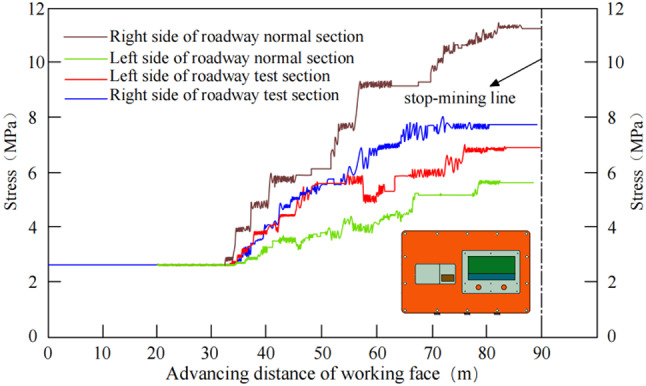
Monitoring of surrounding rock pressure on two sides.
Conclusion
(1)The mechanistical model of roof- cutting for roadway protection in advance of the working face is established, and the stress evolution law of the surrounding rock on the two sides of the advance roadway is revealed. Compared with the existing roof-cutting methods, the innovation of this method (TCPAF) lies in blasting roof-cutting in the withdrawal roadway to protect the advance high-pressure roadway: cutting the long overhanging beam of the roof into a shorter beam, accelerating the roof collapse, cutting off the stress transfer path caused by mining, and reducing the stress on both sides of the leading roadway.
(2) This study mainly considers the division of the weight of the overhanging beam and the severing of the stress transmission path of the overlying strata.This study has identified key parameters for cutting roof protection based on rock fragmentation and expansion characteristics, using stability theories such as “bond-beam” occlusion theory and radial crack penetration theory. The cutting depth, cutting Angle and spacing of drilling holes have been validated through numerical simulations and field experiments.
(3) The method (TCPAF) has been successfully applied in a field industrial test at Pingdingshan No. 6 Mine, where it has been shown to effectively reduce stress on roadway surrounding rock while maintaining efficient production. This method can be tailored to meet different engineering conditions and geological environments, providing a scientific basis for similar conditions encountered in other mines.
Author contributions
Conceptualization, LI Zhaotai. and ZHOU Yuejin; methodology, LI Zhaotai.; software, ZHOU Yuejin; validation, LI Zhaotai, ZHOU Yuejin and XU Xiaoding; formal analysis, XU Xiaoding; investigation, XU Xiaoding; resources, XIAO Yuhang; data curation, LI Zhaotai; writing—original draft preparation, XIAO Yuhang; writing—review and editing, XU Yunong. All authors have read and agreed to the published version of the manuscript.
Data availability
the datasets used and/or analysed during the current study available form the corresponding author on reasonable request.
Declarations
Competing interests
The authors declare no competing interests.
Footnotes
Publisher’s note
Springer Nature remains neutral with regard to jurisdictional claims in published maps and institutional affiliations.
References
- 1.Xue Yi. From tradition to Modern Times:evolution of coal Mining Technology in China. J. Hubei Polytechnic Univ. (Humanit. Social Science). 30 (5), 7–15 (2013). [Google Scholar]
- 2.He Manchao. Comparative Analysis on Stress Field Distributions in roof Cutting Nonpillar Mining Method and Conventional Mining Method JOURNAL OF CHINA COAL SOCIETY3 43626–637 (2018).
- 3.Yuan Chaofeng, Y. et al. Reasonable parameters of roof cutting entry retaining in thin immediate roof and large mining height fully-mechanized face. J. China Coal Soc.44 (7), 1981–1990 (2019). [Google Scholar]
- 4.Wang, Q. Z. P. et al. Automatic roadway formation method by roof cutting with high、strength bolt-grouting in deep coal mine and its validation. J. China Coal Soc.46 (2), 382–397 (2021). [Google Scholar]
- 5.He, M. C., Zhu, G. L. & Guo, Z. B. Longwall mining cuttingcantilever beam theory and 110 mining method in China——The third mining science innovation. J. Rock Mech. Geotech. Eng.7 (5), 483–492 (2015). [Google Scholar]
- 6.Weifeng, X. et al. Theoretical analysis and field measurement of floor failure in gobside entry of cutting roof in confined water mine area. J. China Coal Soc.45 (S2), 581–588 (2020). [Google Scholar]
- 7.Gao Yubing, G. et al. Steady analysis of gob-side entry retaining formed by roof fracturing and control techniques byoptimizing mine pressure. J. China Coal Soc.42 (7), 1672–1681 (2017). [Google Scholar]
- 8.Xingen, M. A. et al. Deformation mechanism and control measures of overlying strata with gob-side entry retainingformed by roof cutting and pressure releasing. Chin. J. Rock Mechan. Eng.48 (3), 474–483 (2019). [Google Scholar]
- 9.Sun Xiaoming, L. & Xin, L. G. Key parameters of gob-side entry retaining formed by roof cut and pressure ReleasingE in thin coal seams. Chin. J. Rock Mechan. Eng.33 (7), 1449–1456 (2014). [Google Scholar]
- 10.Xu, X. D. et al. A new calculation model of blasting damage degree—based on fractal and tie rod damage theory. Eng. Fract. Mech.220, 106619 (2019). [Google Scholar]
- 11.Liu Xiao qiang. Technology of roof cutting pressure relief gob-side entry retaining in Soft fractured Stratum. Coal Sci. anf Technol.41, (S1), 133–134 (2013). [Google Scholar]
- 12.Gao Yubing, H. et al. Experimental study of caving and distribution of gangues influenced by roof fracturing in pillarless mining with gob-side entry retaining. J. China Univ. Min. T Echnology. 47 (1), 21–31 (2018). [Google Scholar]
- 13.Guo Zhibiao, W. & Jiang Cao Tianpei.Reasearch on Key parameters of gob-side entry retaining automatically formed by roof cutting and pressure release. thin coal seam. Ming J. China Univ. Min. Technol.5 (5), 879–885 (2016). [Google Scholar]
- 14.Yuan Chaofeng, Y. et al. Reasonable parameters of roof cutting entry retaining in thin immediate roof and large mining height fully-mechanized face. Journal of China Coal Society, 44(7): 1981-1990 (2019).
- 15.Jia Chuan-yang, Jiang Yu-jing. Laboratory and numerical experiments on pressure relief mechanism of large-diameter boreholes. Chinese Journal of Geotechnical Engineering, 39(6): 1115–1122 (2017).
- 16.Zheng, K. G., Liu, Y., Zhang, T. & Zhu, J. Z. Mining-induced stresscontrol by advanced hydraulic fracking under a thick hard rooffor top coal caving method: a case study in the Shandong miningarea, China. Min Basel11(12):1 (2021).
- 17.Shen B. Coal mine roadway stability in soft rock: a case study. Rock Mech Rock Eng47(6):2225–2238 (2014)
- 18.Chen Dongdong, W. & Xiaoyu, X. Shengrong. Study on the ThinPlate Model with Elastic Foundation boundary of overlying Stratafor Backfill Mining. Math. Probl. Eng., (4): 1–15. (2020).
- 19.Zhang Guofeng, X. & Youqing Ge Pengtao.Research on cut gob-side entry retaining in thin coal seam of Tangshan ditch. Chin. J. Rock Mechan. Eng.35 (7), 1397–1406 (2016). [Google Scholar]
- 20.Li & Xuehua Ju Minghe.Study of influential factors on the stability of narrow coal pillar in gob-side entry driving and its engineering application. J. Min. Saf. Eng.33 (5), 761–769 (2016). [Google Scholar]
- 21.Qian Ming gao. Kuangshan Yali Yanceng Kongzhi[M].Xuzhou84–87 (China University of Mining and Technology, 2010).
- 22.Zhao Yi. Roof cutting and pressure relief with dense drilling for roadway protection in Songxinzhuang Coal Mine. Coal Eng.55 (5), 47–48 (2023). [Google Scholar]
- 23.Chen, S. Zhao Fei,.Determination of key parameters of gob-side entry retaining by cutting roof and its application to a deep mine. Rock. Soil. Mech.40 (1), 12 (2019). [Google Scholar]
- 24.Li, J. Surrounding Rock Control mechanism and application of gob-side entry retaining by cutting roof in 11101 Gangue Filling Working face of Jingu Coal Mine[D].Xuzhou: China University of Mining and Technology, (2023).
- 25.Yang, J., He, M. C. & Cao, C. Design principles and key technologies of gob side entry retaining by roof pre-fracturing. Tunn. Undergr. Sp Tech.90, 309–318 (2019a). [Google Scholar]
- 26.Yang, J. et al. Stability analysis of the entry in a new mining approach influenced by roof fracture position. Sustain. Basel. 11 (22), 1 (2019b). [Google Scholar]
- 27.Qiang Fu Jun Yang Hongxu Song Study on the Method. Of Pressure Relief and Energy Absorption for protecting Roadway under Thick and hard roof. Rock Mech. Rock Eng.56, 7177–7196 (2023). [Google Scholar]
Associated Data
This section collects any data citations, data availability statements, or supplementary materials included in this article.
Data Availability Statement
the datasets used and/or analysed during the current study available form the corresponding author on reasonable request.