Abstract
Growing emission of environmentally-hazardous greenhouse pollutants (especially CO2) has motivated the researchers to apply gas–liquid membrane contactors as an easy-to-operate and cost-effective technique for increasing their separation efficiency from different sources. In the current decades, ionic liquids (ILs) have shown their potential in the gas separation industry owing to their noteworthy advantages such as great capacity, excellent adjustability and suitable thermal/chemical stability compared to commonly-employed amine absorbents. This investigation aims to analytically/numerically determine the separation yield of CO2 from CO₂/N2 gaseous flow using novel -Ethyl-3-methylimidazolium dicyanamide ([emim][C2N3]) IL inside the gas–liquid contactor. To fulfill the ultimate purpose, a CFD simulation has been proposed using COMSOL Multiphysics software to predict the results. Comparison of model outcome with experimental data has shown brilliant concurrence with the average relative deviation of almost 5%. Evaluation of the results has shown the excellent performance of [emim][C2N3] IL for the removal of CO2 (Separation efficiency of around 100%). Finally, the effects of some module/membrane parameters on increasing or decreasing the separation efficiency has been studies in detail.
Keywords: Ionic liquid, CFD simulation, CO2 removal, Membrane contactor, Modeling
Subject terms: Computational science, Chemical engineering
Introduction
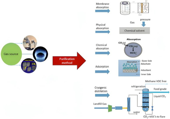
The emergence of economic development and industrial revolution since the twentieth century has significantly deteriorated the quality of climate and environment1–4. CO2 has long been perceived as the leading greenhouse gas, which its increasing emission to the atmosphere in the current decades has exacerbated unfavorable environmental-based phenomena like wildfires, climate change and acid rain5–7. Therefore, finding environmentally-benign, cost-effective and novel procedures for satisfying the market demand for efficient management of CO2 emission. In the last decades, different gas separation approaches including low-temperature phase separation, cryogenic distillation and membrane-based absorption have been commonly employed. With the aim of using these techniques, disparate gas–liquid contact procedures (i.e., packed towers, spray towers and bubble towers) have been used8–11. Figure 1 schematically presents different gas separation techniques in industries.
Fig. 1.
Different prevalent techniques for the separation of gas1.
In the current two decades, industrial application of membrane contactor has attracted the attentions of scientists in the world. This technology has shown its great capability to incorporate the positive advantages of molecular absorption (excellent selectivity) and membrane separation (compactness)2,12–14. The existence of noteworthy advantages like modularity, separated flowing of gas and liquid phases and high interfacial area in the gas–liquid contactors could significantly decline the size and facilitate operation15–17.
Various endeavors have recently been conducted to apply more effective, green and operationally-safe absorbents for substituting with detrimental alkanolamine solutions in the process of CO2 molecular separation. Ionic liquids (ILs) refer to a relatively novel class of chemical absorbent consisted of organic cations and inorganic anions18,19. They have recently been considered as promising alternatives for amine solutions thanks to their outstanding physicochemical properties such as great capacity for the separation of CO2, excellent adjustability and better thermal/chemical stability than commonly-employed amine absorbents20–23.
The recovery of CO2 may be regarded as an important energy-intensive level in CO2 processes. Therefore, the analysis of regeneration energies is of prime necessity to evaluate the possibility of applying novel types of liquid absorbents like ILs in industrial applications21,24. It has been understood from different scientific investigations that the simplicity of regeneration is a considerable advantage of ILs. The experimental results have illustrated the fact that the required regeneration energy for different prevalent types of ILs is significantly competitive with benchmark amine solutions (4.3 kJ g (CO2)−1 vs 2.3–4.5 kJ g (CO2)−1). Therefore, better efficiency and reasonable required energy for regeneration has made ILs promising for application in CO2-separation technologies25.
This scientific research aims to analytically/numerically study the feasibility of using novel [emim][C2N3] IL inside the gas–liquid contactor for increasing CO2 separation. To hit this point, a CFD-based simulation using COMSOL Multiphysics software is applied to solve partial differential equations (PDEs) in different geometries of contactor. Finally, the effects of some module/membrane parameters on increasing or decreasing the separation efficiency are analyzed and the results are discussed in detail.
Model development
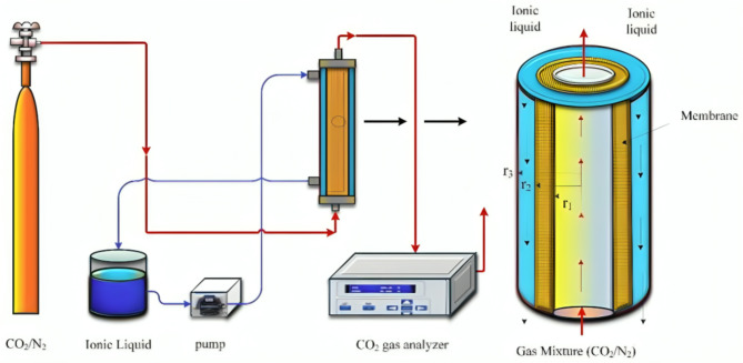
The schematic illustration of the experimental set up employed by Ghasem for the separation of CO2 from CO₂/N2 flow is demonstrated in Fig. 2.
Fig. 2.
Schematic demonstration of the experimental set up and the geometry of gas–liquid contactor for the separation of CO226.
In order to facilitate the simulation process of CO2 separation using [emim][C2N2] in the membrane contactor, the following mathematical/theoretical assumptions were implemented.
The employed system is assumed isothermal and steady state
Filling of membrane micropores with only gas molecules (non-wetted mode)
Application of Henry’s law for the expression of equilibrium between gas and IL
No reaction occurs inside the gas phase
Counter-current flow of gaseous flow and IL
Laminar regime of fluids
Hydrophobicity nature of membrane
Application of Happel’s free surface model (HFSM) for the approximation of hypothetical effective radius around each hollow fiber (r3)
Essential module/membrane-based parameters following with feed conditions for the development of theoretical simulation is listed in Table 1. COMSOL Multiphysics is known as a promising commercial-package finite element-based analyzer/solver utilized for disparate physics and engineering applications. This software has recently shown its noteworthy potential to facilitate common physics-based user interfaces and coupled systems of PDEs27–29. In this paper, the authors have made their ultimate efforts to increase the precision of modeling using UMFPACK solver. Computational time for solving the existed PDEs using this solver was approximately 2 min.
Table 1.
The detailed specifications and feed conditions for model development30.
| Parameter | Unit | Value |
|---|---|---|
Inner radius of membrane ( ) ) |
m | 1.1 × 10⁻⁴ |
Outer radius of membrane ( ) ) |
m | 1.5 × 10⁻⁴ |
Thickness of membrane ( ) ) |
m | 0.4 × 10⁻⁴ |
| Contactor length (L) | m | 0.115 |
| Number of fibers (n) | – | 2300 |
Module packing factor (
|
– | 0.39 |
Porosity ( ) ) |
– | 0.4 |
Tortuosity ( ) ) |
– | 2.5 |
| Inlet concentration of CO2 | Vol% | 15 |
| Liquid flow rate (Ql) | ml/min | 50–90 |
| Gas flow rate (Qg) | ml/min | 50–100 |
Table 2 presents the prominent transport equations along with their associated boundary conditions in the tube side of membrane contactor5,31,32.
Table 2.
Governing equations and corresponded boundary conditions in the tube.
| Mass transfer | Momentum transfer |
|---|---|
 (1) (1) |
 (2) (2) |
| Boundary conditions | |
 (3) (3) | |
 (4) (4) | |
 (5) (5) | |
 (6) (6) | |
All parameters have been defined in the nomenclature list. Non-wetted mode of operation is an employed assumptions in this manuscript, which means the filling of membrane pores with only gaseous molecules. Thus, diffusion is the only mass transport mechanism through the microporous fibers33–35. Table 3 enlists transport equations and boundary conditions inside the membrane12,36–41.
Table 3.
Principal equations and boundary conditions inside the membrane.
| Mass transfer | Boundary conditions |
|---|---|
|
|
|
Principal transport equations and boundary conditions in the shell side are enlisted in Table 4. Application of two aforementioned assumption (laminar flow pattern and the HFSM model eventuates in deriving the velocity profile in this compartment (Eq. 14)32,42–44.
Table 4.
Principal transport equations and boundary conditions inside the shell.
| Mass transfer | Momentum transfer |
|---|---|
 (13) (13) |
 (14) (14) |
 (15) (15) | |
| Boundary conditions | |
 (16) (16) | |
 (17) (17) | |
 (18) (18) | |
 (19) (19) | |
Equation 15 is employed to prognosticate the hypothetical radius around each hollow fiber33,45. Based on this equation r3 is calculated 1.92 × 10⁻⁴ m. Table 5 presents essential physical, mechanical, transport and chemical parameters for model development.
Table 5.
The essential physical, mechanical, transport and chemical parameters for model development.
Mesh study
The prominent purpose of meshing is the segmentation of all domains of membrane contactor to finer dimensions to facilitate the study of effective parameters at each domain point with greater accuracy5. As would be expected, as the number of meshes increases, the modeling accuracy (as a favorable parameter) and computational time (as an unfavorable parameter) increases. Therefore, an optimum number of mesh needs to be provided to reach the maximum accuracy in low computational time. Mapped meshing approach has been employed in this research to divide the whole geometry of contactor into smaller cells thank to its indisputable capability to cover all points of existed domain52. Figure 3 shows the employed mapped meshes in different sides of contactor. As shown, the meshes in the membrane domain in the area of CO2-IL contact is finer to facilitate the study of operational parameters with superior accuracy and lower error. The mapped meshing outcome has shown that after the 255th mesh, no significant alteration in the concentration of CO2 in the outlet of the tube occurs, which shows the independency of simulation results after the mesh number of 255.
Fig. 3.
Mapped meshing for different domains of membrane contactor.
Results and discussion
Validation of model outcomes
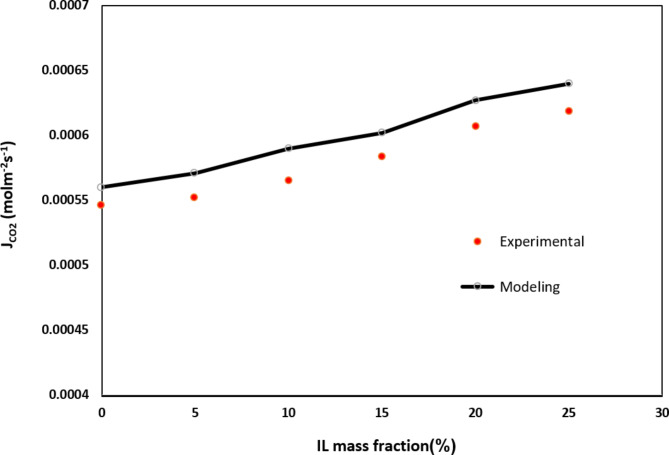
Owing to the lack of steady-state experimental data for [emim][C2N3] IL, simulation results were compared with the obtained data from the experiment of Rostami et al. for [Bmim][BF4] IL in different IL mass fraction53. Evaluation of data shows a favorable concurrence with average relative error of almost 3.65%. Figure 4 and Table 6 compare experimental and simulation outcomes for the molar flux of CO2 in different IL mass fraction.
Fig. 4.
Validation of model outcome with achieved experimental data. Ql = 25 ml/min, Qg = 70 ml/min, r1 = 1.375 × 10⁻⁴ m, r2 = 1.85 × 10⁻⁴ m, L = 65 mm Data was obtained by the research of Rostami et al.53.
Table 6.
Validation of developed model. Ql = 25 ml/min, Qg = 70 ml/min, r1 = 1.375 × 10⁻⁴ m, r2 = 1.85 × 10⁻⁴ m, L = 65 mm. Data was obtained by the research of Rostami et al. 53.
| IL mass fraction (%) | CO2 molar flux (mol m−2 s−1) (experimental) | CO2 molar flux (mol m−2 s−1) (Modeling) | Average relative error (%) |
|---|---|---|---|
| 0 | 5.46 × 10⁻⁴ | 5.6 × 10⁻⁴ | 2.5 |
| 5 | 5.52 × 10⁻⁴ | 5.71 × 10⁻⁴ | 3.32 |
| 10 | 5.65 × 10⁻⁴ | 5.90 × 10⁻⁴ | 4.2 |
| 15 | 5.83 × 10⁻⁴ | 6.02 × 10⁻⁴ | 2.57 |
| 20 | 6.07 × 10⁻⁴ | 6.27 × 10⁻⁴ | 4.3 |
| 25 | 6.19 × 10⁻⁴ | 6.4 × 10⁻⁴ | 3.28 |
CO2 Concentration distribution
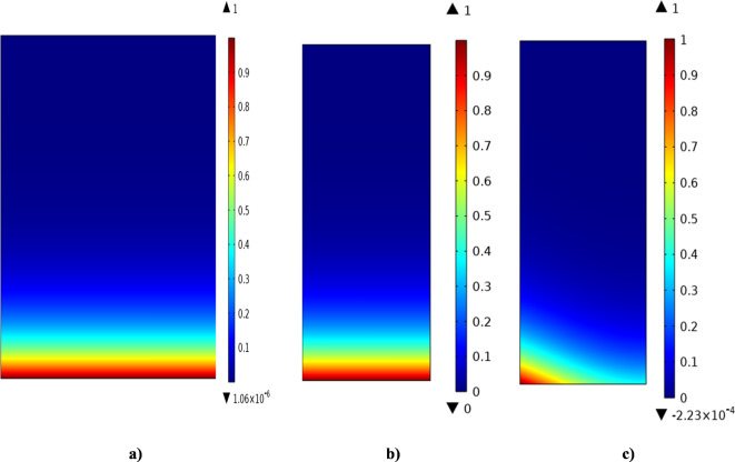
Dimensionless concentration gradient of CO2 through the tube side of contactor utilizing [emim][C2N3] IL is demonstrated in Fig. 5. By the countercurrent flowing of gaseous mixture in the tube (from down to top) and [emim][C2N3] IL in the shell compartment (from top to down) of contactor, CO2 molecules diffuse from the tube to the walls of porous membrane and from the porous walls to the shell. It is important to note that the governing mass transfer mechanisms in the axial and radial coordinates are convection (due to the motion of fluids) and diffusion (due to concentration gradient). As demonstrated, the dimensionless concentration amount of CO2 molecules reduces as it moves forward in the contactor however.
Fig. 5.
Dimensionless CO2 concentration profile through the (a) tube, (b) membrane and (c) shell of contactor using [emim][C2N3] IL.
Moreover, the CO2 dimensionless concentration (CCO2,tube/CCO20) in the tube-membrane interfacial zone is depicted in Fig. 6. At z = 0, this amount is maximum (1) and declines to 0 at the tube outlet (z = L) using employed IL, which implies 100% removal of inlet CO2 to the membrane module. The substantial decrement in the CO2 dimensionless concentration is mainly owing to the great efficiency of [emim][C2N3] IL to instantly react with CO2 molecules and absorb them.
Fig. 6.
Axial dimensionless concentration of the CO2 in tube-membrane interfacial zone.
Effect of module length
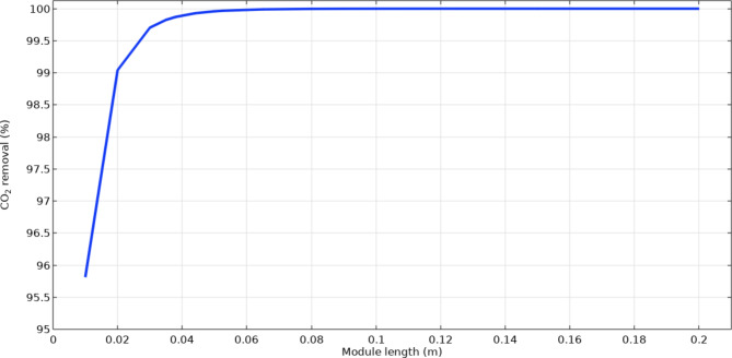
Another module-based parameter, which can influence the mass transfer and thus, the removal percentage of CO2 within the membrane contactor is module length. Enhancement of the operational length of module can increase the gas–liquid residence time, which results in improving their contact inside and therefore, mass transfer rate. Ultimately, increase in the mass transfer rate can substantially intensifies the separation of CO2 employing [emim][C2N3] IL. Figure 7 shows the influence of module length on the absorption yield of CO2. When the length increases from 0.01 to 0.2 m, the removal yield of CO2 improves from 95.8 to 100%.
Fig. 7.
Effect of module length on the CO2 removal utilizing emim[C2N3] IL.
Effect of hollow fibers’ count
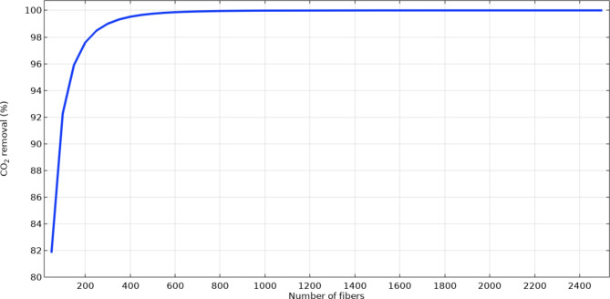
Figure 8 tries to analytically investigates the role of the fibers’ counts on the separation of CO2 inside the contactor. As shown, increment in the number of fibers from 20 to 2500 positively enhances the absorption rate from 82 to 100% owing to providing better opportunity for the contact between CO2 and [emim][C2N3] IL and as the result, improving the mass transfer. Increase in the fibers’ counts inside the contactor considerably improves the mass transfer area between the gas and IL significantly, which has positive influence on the separation efficiency.
Fig. 8.
The operational effect of hollow fibers number on the CO2 separation efficiency.
Effect of gas flow rate
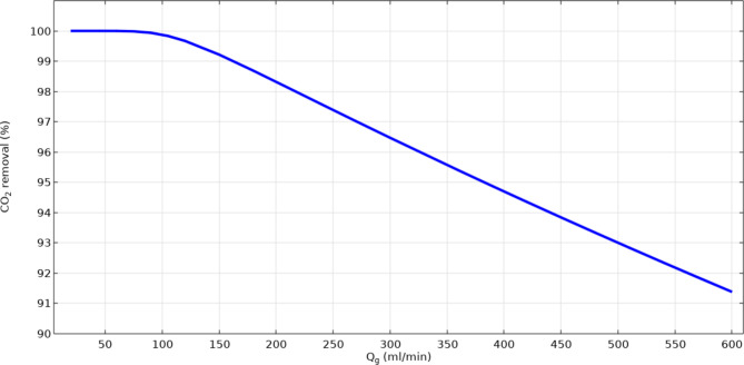
Figure 9 numerically compares the absorption yield of CO2 through the gas–liquid contactor using [emim][C2N3] IL in different gas flow rates. As demonstrated, enhancement in the flow rate of gas intensifies the resistance toward the mass transfer of CO2 molecules, reduces the residence time of gas and as the result, decreases the mass transfer of CO2. It is concluded from the figure that by increasing the flow rate of gas in the shell of contactor from 20 to 150 ml min−1, the removal of CO2 decreases from 100 to about 91.4% using [emim][C2N3] IL.
Fig. 9.
Influence of gas flow rate on the CO2 sequestration performance utilizing emim[C2N3] IL.
Conclusion
This research aimed to numerically assess the operational efficiency of [emim][C2N3] IL for separating CO2 greenhouse pollutant from CO₂/N2 mixture. For this purpose, a 2D CFD-based simulation was developed using COMSOL Multiphysics software to prognosticate the outcomes. Moreover, UMFPACK numerical solver was applied to analyze to governing mass transfer equations in disparate geometries of gas–liquid contactor. To ensure the validity of model results, they were compared with experimental data. There was a brilliant concurrence between the obtained results of simulation and literature data with the average relative deviation of almost 3.6%. With the removal efficiency of around 100%, [emim][C2N3] IL is introduced as a reliable and operationally-effective liquid absorbent for removing CO2. Analysis of the results showed that increase in the amount of some module/membrane-based factors like porosity, number of fibers and module length enhance the sequestration yield due to improving mass transfer rate, residence time and gas–liquid contact. But increment in the flow rate of gas deteriorate the absorption efficacy due to increasing the resistance toward mass transfer and decreasing the residence time of gas in the membrane module.
Acknowledgements
The authors are thankful to the Researchers Supporting Project number (RSP2025R516) at King Saud University, Riyadh, Saudi Arabia.
List of symbols

Internal radius of each hollow fiber (
 )
)
Exterior radius of each hollow fiber (
 )
)
Approximated hypothetical effective radius around each fiber (
 )
)
Length of membrane module (
 )
)
CO2 diffusivity in the shell (
 )
)
CO2 diffusivity in the membrane (
 )
)
CO2 diffusivity of the [emim][C2N3] IL in the shell (
 )
)
Dimensionless CO2 solubility

Number of fibers

Pressure (
 )
)
Initial CO2 concentration in the gas phase (
 )
)
Liquid flow rate (
 )
)
Gas flow rate (
 )
)
Temperature (
 )
)
Average axial velocity of the liquid through the shell (
 )
)
Average axial velocity of gas through the tube (
 )
)
Transformed constant (
 )
)
Porosity

Tortuosity

Packing factor
Author contributions
A.A: Writing draft, Investigation W.M: Methodology, Software, Analysis A.O: Funding, Project administration.
Data availability
All data are available within the manuscript.
Competing interests
The authors declare no competing interests.
Footnotes
Publisher’s note
Springer Nature remains neutral with regard to jurisdictional claims in published maps and institutional affiliations.
References
- 1.Li, L. et al. Research progress in gas separation using hollow fiber membrane contactors. Membranes10(12), 380 (2020). [DOI] [PMC free article] [PubMed] [Google Scholar]
- 2.Imtiaz, A. et al. A critical review in recent progress of hollow fiber membrane contactors for efficient CO2 separations. Chemosphere325, 138300 (2023). [DOI] [PubMed] [Google Scholar]
- 3.Vaezi, M. et al. Modeling of CO2 absorption in a membrane contactor containing 3-diethylaminopropylamine (DEAPA) solvent. Int. J. Greenh Gas Control127, 103938 (2023). [Google Scholar]
- 4.Cao, Y., TaghvaieNakhjiri, A. & Ghadiri, M. Computational fluid dynamics comparison of prevalent liquid absorbents for the separation of SO2 acidic pollutant inside a membrane contactor. Sci. Rep.13(1), 1300 (2023). [DOI] [PMC free article] [PubMed] [Google Scholar]
- 5.Nakhjiri, A. T. et al. Experimental investigation and mathematical modeling of CO2 sequestration from CO2/CH4 gaseous mixture using MEA and TEA aqueous absorbents through polypropylene hollow fiber membrane contactor. J. Membr. Sci.565, 1–13 (2018). [Google Scholar]
- 6.Nunes, L. J. The rising threat of atmospheric CO2: A review on the causes, impacts, and mitigation strategies. Environments10(4), 66 (2023). [Google Scholar]
- 7.Ramonet, M., et al., CO₂ in the atmosphere: Growth and trends since 1850. in Oxford Research Encyclopedia of Climate Science (2023).
- 8.Ghadiri, M. et al. Modelling tyramine extraction from wastewater using a non-dispersive solvent extraction process. Environ. Sci. Pollut. Res.27(31), 39068–39076 (2020). [DOI] [PubMed] [Google Scholar]
- 9.He, T. et al. High ethane content enables efficient CO2 capture from natural gas by cryogenic distillation. Sep. Purif. Technol.352, 128153 (2025). [Google Scholar]
- 10.Khan, U. et al. Assessing absorption-based CO2 capture: Research progress and techno-economic assessment overview. Carb. Capt. Sci. Technol.8, 100125 (2023). [Google Scholar]
- 11.Xu, Y. et al. CFD investigation of post-combustion CO2 capture using an industrial spray tower: Regulation effects of spray schemes. Chem. Eng. Sci.293, 120053 (2024). [Google Scholar]
- 12.Shirazian, S. et al. Theoretical investigations on the effect of absorbent type on carbon dioxide capture in hollow-fiber membrane contactors. Plos one15(7), e0236367 (2020). [DOI] [PMC free article] [PubMed] [Google Scholar]
- 13.Kianfar, E. A review of recent advances in carbon dioxide absorption–stripping by employing a gas–liquid hollow fiber polymeric membrane contactor. Polym. Bull.80(11), 11469–11505 (2023). [Google Scholar]
- 14.Cao, Y. et al. Recent advancements in molecular separation of gases using microporous membrane systems: A comprehensive review on the applied liquid absorbents. J. Mol. Liq.337, 116439 (2021). [Google Scholar]
- 15.Ramezani, R., Di Felice, L. & Gallucci F. A review on hollow fiber membrane contactors for carbon capture: Recent advances and future challenges. Processes10 (2022). 10.3390/pr10102103
- 16.Shiravi, A. et al. Hollow fiber membrane contactor for CO2 capture: A review of recent progress on membrane materials, operational challenges, scale-up and economics. Carb. Capt. Sci. Technol.10, 100160 (2024). [Google Scholar]
- 17.Pishnamazi, M. et al. Computational study on SO2 molecular separation applying novel EMISE ionic liquid and DMA aromatic amine solution inside microporous membranes. J. Mol. Liq.313, 113531 (2020). [Google Scholar]
- 18.Llaver, M. et al. 16 Ionic liquids. In Analytical Sample Preparation With Nano- and Other High-Performance Materials (eds Lucena, R. & Cárdenas, S.) 427–451 (Elsevier, 2021). [Google Scholar]
- 19.Sowbhagyam, D. V. Ionic liquids as green solvents: A comprehensive review. Int. Res. J. Adv. Eng. Hub (IRJAEH)2(02), 220–224 (2024). [Google Scholar]
- 20.Zhang, K. & Wang, R. A critical review on new and efficient adsorbents for CO2 capture. Chem. Eng. J.485, 149495 (2024). [Google Scholar]
- 21.Pishnamazi, M. et al. Computational investigation on the effect of [Bmim][BF4] ionic liquid addition to MEA alkanolamine absorbent for enhancing CO2 mass transfer inside membranes. J. Mol. Liq.314, 113635 (2020). [Google Scholar]
- 22.Lei, Z. et al. Introduction Ionic Liquids for Diverse Applications 7533–7535 (ACS Publications, 2024). [DOI] [PubMed] [Google Scholar]
- 23.Cao, Y., Taghvaie Nakhjiri, A. & Sarkar, S. Modelling and simulation of waste tire pyrolysis process for recovery of energy and production of valuable chemicals (BTEX). Sci. Rep.13(1), 6090 (2023). [DOI] [PMC free article] [PubMed] [Google Scholar]
- 24.Dołżonek, J., et al., Regeneration, recovery, and removal of ionic liquids. in Encyclopedia of Ionic Liquids, 1168–1176 (Springer, 2023).
- 25.Yousefe, M. et al. Readily regenerable amine-free CO2 sorbent based on a solid-supported carboxylate ionic liquid. J. Environ. Manag.334, 117469 (2023). [DOI] [PubMed] [Google Scholar]
- 26.Ghasem, N., Modeling the Effectiveness of hollow fiber membrane contactors for CO2 capture using ionic liquids: A comparative study. J. Membr. Sci. Res.9(4) (2023).
- 27.Nakhjiri, A. T. et al. The effect of membrane pores wettability on CO2 removal from CO2/CH4 gaseous mixture using NaOH, MEA and TEA liquid absorbents in hollow fiber membrane contactor. Chin. J. Chem. Eng.26(9), 1845–1861 (2018). [Google Scholar]
- 28.Sumayli, A. et al. Comparison of novel ionic liquids and pure water for CO2 separation through membrane contactor: CFD simulation and thermal analysis. Case Stud. Therm. Eng.53, 103856 (2024). [Google Scholar]
- 29.Sumayli, A., Mahdi, W. A. & Alshahrani, S. M. Numerical evaluation of CO2 molecular removal from CO2/N2 mixture utilizing eco-friendly [emim][OAc] and [emim][MeSO4] ionic liquids inside membrane contactor. J. Mol. Liq.396, 123958 (2024). [Google Scholar]
- 30.Qazi, S. et al. CO2 capture in a hollow fiber membrane contactor coupled with ionic liquid: Influence of membrane wetting and process parameters. Sep. Purif. Technol.233, 115986 (2020). [Google Scholar]
- 31.Razavi, S. M. R., Shirazian, S. & Nazemian, M. Numerical simulation of CO2 separation from gas mixtures in membrane modules: Effect of chemical absorbent. Arab. J. Chem.9(1), 62–71 (2016). [Google Scholar]
- 32.Bird, R., Stewart, W. & Lightfoot, E. Transport Phenomena 2nd edn. (John Wiely and Sons. Inc., 2002). [Google Scholar]
- 33.Faiz, R. & Al-Marzouqi, M. Mathematical modeling for the simultaneous absorption of CO2 and H2S using MEA in hollow fiber membrane contactors. J. Membr. Sci.342(1), 269–278 (2009). [Google Scholar]
- 34.Nakhjiri, A. T. et al. Modeling and simulation of CO2 separation from CO2/CH4 gaseous mixture using potassium glycinate, potassium argininate and sodium hydroxide liquid absorbents in the hollow fiber membrane contactor. J. Environ. Chem. Eng.6(1), 1500–1511 (2018). [Google Scholar]
- 35.Pishnamazi, M., et al., Computational study on SO2 molecular separation applying novel EMISE ionic liquid and DMA aromatic amine solution inside microporous membranes. J. Mol. Liq. 113531 (2020)
- 36.Pishnamazi, M. et al. Mechanistic modeling and numerical simulation of axial flow catalytic reactor for naphtha reforming unit. Plos One15(11), e0242343 (2020). [DOI] [PMC free article] [PubMed] [Google Scholar]
- 37.Afza, K. N., Hashemifard, S. & Abbasi, M. Modelling of CO2 absorption via hollow fiber membrane contactors: Comparison of pore gas diffusivity models. Chem. Eng. Sci.190, 110–121 (2018). [Google Scholar]
- 38.Al-Marzouqi, M. H. et al. Modeling of CO2 absorption in membrane contactors. Sep. Purif. Technol.59(3), 286–293 (2008). [Google Scholar]
- 39.Nakhjiri, A. T. & Roudsari, M. H. Modeling and simulation of natural convection heat transfer process in porous and non-porous media. Appl. Res. J.2(4), 199–204 (2016). [Google Scholar]
- 40.Marjani, A. et al. Evaluation of potassium glycinate, potassium lysinate, potassium sarcosinate and potassium threonate solutions in CO2 capture using membranes. Arab. J. Chem.14(3), 102979 (2021). [Google Scholar]
- 41.Babanezhad, M. et al. Computational modeling of transport in porous media using an adaptive network-based fuzzy inference system. ACS Omega5(48), 30826–30835 (2020). [DOI] [PMC free article] [PubMed] [Google Scholar]
- 42.Al-Marzouqi, M. et al. Modeling of chemical absorption of CO2 in membrane contactors. Sep. Purif. Technol.62(3), 499–506 (2008). [Google Scholar]
- 43.Eslami, S. et al. Modeling and simulation of CO 2 removal from power plant flue gas by PG solution in a hollow fiber membrane contactor. Adv. Eng. Softw.42(8), 612–620 (2011). [Google Scholar]
- 44.Happel, J. Viscous flow relative to arrays of cylinders. AIChE J.5(2), 174–177 (1959). [Google Scholar]
- 45.Nakhjiri, A. T. & Heydarinasab, A. CFD analysis of CO2 sequestration applying different absorbents inside the microporous PVDF hollow fiber membrane contactor. Period. Polytech. Chem. Eng.64(1), 135–145 (2020). [Google Scholar]
- 46.Morgan, D., Ferguson, L. & Scovazzo, P. Diffusivities of gases in room-temperature ionic liquids: Data and correlations obtained using a lag-time technique. Ind. Eng. Chem. Res.44(13), 4815–4823 (2005). [Google Scholar]
- 47.Hayduk, W. & Cheng, S. Review of relation between diffusivity and solvent viscosity in dilute liquid solutions. Chem. Eng. Sci.26(5), 635–646 (1971). [Google Scholar]
- 48.Paduszynski, K. & Domanska, U. Viscosity of ionic liquids: an extensive database and a new group contribution model based on a feed-forward artificial neural network. J. Chem. Inf. Model.54(5), 1311–1324 (2014). [DOI] [PubMed] [Google Scholar]
- 49.National Center for Biotechnology Information (2024). PubChem Compound Summary for CID 11159638, .E.M.D.R.S., 2024 from https://pubchem.ncbi.nlm.nih.gov/compound/1-Ethyl-3-methylimidazolium-dicyanamide.
- 50.Soriano, A. N., Doma, B. T. Jr. & Li, M.-H. Carbon dioxide solubility in some ionic liquids at moderate pressures. J. Taiwan Inst. Chem. Eng.40(4), 387–393 (2009). [Google Scholar]
- 51.Gómez-Coma, L., Garea, A. & Irabien, A. Mass transfer analysis of CO2 capture by PVDF membrane contactor and ionic liquid. Chem. Eng. Technol.40(4), 678–690 (2017). [Google Scholar]
- 52.Eslami, S. et al. Modeling and simulation of CO2 removal from power plant flue gas by PG solution in a hollow fiber membrane contactor. Adv. Eng. Softw.42(8), 612–620 (2011). [Google Scholar]
- 53.Rostami, S., Keshavarz, P. & Raeissi, S. Experimental study on the effects of an ionic liquid for CO2 capture using hollow fiber membrane contactors. Int. J. Greenh. Gas Control69, 1–7 (2018). [Google Scholar]
Associated Data
This section collects any data citations, data availability statements, or supplementary materials included in this article.
Data Availability Statement
All data are available within the manuscript.


