Abstract
This research paper presents an advanced AI-driven hybrid power quality management system for electrical railways that addresses critical challenges in 25 kV AC traction networks through a novel integration of single-phase PV-UPQC with ANN-Lyapunov control architecture. The system effectively manages voltage unbalance exceeding 2%, high THD, voltage variations of ± 10%, and poor power factor through a dual-approach methodology combining ANN-based reference signal generation with Lyapunov optimization, enabling dynamic parameter tuning and real-time load adaptation. MATLAB/Simulink simulations validate the system’s superior performance, demonstrating significant improvements, including voltage unbalance reduction from 1.5 to 0.8%, THD reduction below 1%, unity power factor correction, 40% faster dynamic response, and DC link voltage regulation within ± 2%, while maintaining 95% overall system efficiency. Integrating ANN-based shunt and series APF control, Lyapunov optimization, and PV integration establishes a robust framework for enhanced energy efficiency and power quality management in modern railway systems.
Supplementary Information
The online version contains supplementary material available at 10.1038/s41598-025-85393-5.
Keywords: Power Quality, Artificial neural networks, Lyapunov Control, Photovoltaic integration, Unified Power Quality Conditioner
Subject terms: Engineering, Electrical and electronic engineering
Introduction
This research introduces the first Lyapunov optimization for UPQC control parameters in railway applications and provides an effective power quality enhancement with maximum system stability. That is why the investigated method of integrating PV systems with UPQC through AI-based control is one of the most innovative and prospective solutions for sustainable power quality management in electrified railways. Railway electrification has become more popular worldwide to reduce fossil fuel use and emissions. However, it presents technical issues regarding power quality since traction loads are single-phase, nonlinear, with regenerative braking1. This leads to issues such as voltage unbalances, harmonics, voltage sag/swell, and poor power factor in the three-phase utility grid supplying the traction substations2,3. Earlier methods of controlling these problems have included special traction transformers, passive filters, and static var compensators (SVCs). Conventional power quality mitigating equipment such as passive filters and SVCs have their limitations – they take a long time to respond to PQ disturbances, occupy considerable physical space that is difficult to accommodate, and are known to cause resonance issues with the power systems. Conventional active power filters, on the other hand, suffer from limited response time and varied levels of Compensation; this is the case with new advanced active power filters that utilize power electronics to compensate for disturbances in less time. With advancements in power electronics, active power filters (APFs) have emerged as a superior solution for improving power quality4. The unified power quality conditioner (UPQC) is an APF-based custom power device that integrates shunt and series compensation5. It can simultaneously act as a harmonic isolator between the load and supply, a voltage regulator at the load terminal, and a reactive power compensator for power factor correction6. A few studies have investigated the application of UPQC for railway power quality enhancement7. However, the control of UPQC is quite complex, as it requires fast and accurate reference generation under dynamic load conditions. Conventional methods based on instantaneous reactive power (IRP) theory are limited8. Recently, artificial intelligence (AI) techniques like fuzzy logic, artificial neural networks (ANNs), adaptive neuro-fuzzy, etc., have shown promise for APF control due to their robustness, adaptability, and nonlinearity9.
Moreover, the control parameters need to be optimally tuned to ensure system stability and desired performance. Lyapunov optimization is a powerful technique that can maximize a utility function subject to stability constraints10. It has been successfully applied to power system control and energy management11. Lyapunov control functions are extended to handle state constraints and obstacles while ensuring system stability and equilibrium through nonsmooth complete CLF formulation33. However, its application to power quality control in railways has yet to be explored in UPQC. The energy storage systems enhance the AI-based UPQC model by providing faster response to load variations, better DC link voltage stability, and improved power factor correction through energy buffering capabilities.
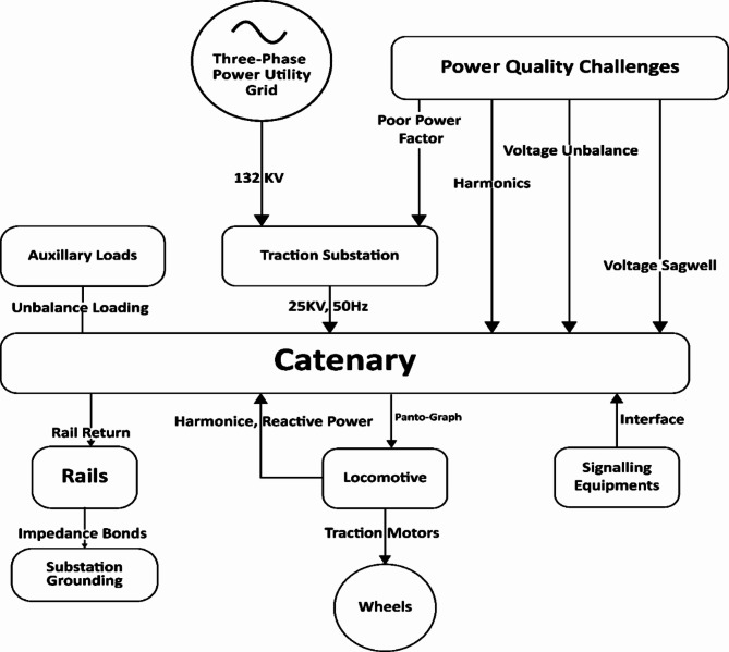
Figure 1 illustrates the typical configuration of a 25 kV AC traction system with power quality challenges. Table 1 compares the features and limitations of various power quality mitigation methods. This paper proposes a novel AI-based hybrid control for a single-phase UPQC using Lyapunov optimization to improve power quality in electrified railway systems.
Fig. 1.
Configuration of a 25 kV AC traction system.
Table 1.
The features and limitations of various power quality mitigation methods.
| Mitigation Method | Features | Limitations |
|---|---|---|
| Unified Power Quality Conditioner (UPQC)11 | Simultaneously resolves current and voltage-related power quality issues | Complex configuration and control |
| Improved control strategies allow for higher-quality power production. | ||
| Solar PV Integration with Grid12 | Utilizes novel adaptive controllers for voltage-sensitive loads | Requires coordination with other devices like OLTC and SVC for effective voltage regulation |
| Employs regulation strategies to mitigate voltage fluctuations | ||
| Distribution Static Compensator (DSTATCOM)12 | Utilizes voltage controller for improved performance13 | Efforts in optimal placement and sizing have been limited |
| Stochastic optimal planning considers uncertainties in loads and solar irradiance. | Efficient allocation for unbalanced distribution networks needs further research. | |
| Active Power Filter (APF) | Mitigates power quality issues in grid integration of wind and PV systems | Requires proper design and control for effective performance |
| Phase coordinate-based APF effective for harmonic mitigation. | ||
| Dynamic Voltage Restorer (DVR) | Enhances voltage sag in grid-connected hybrid PV-wind power system | Integration with smart grids and microgrids needs further research |
| Improved power converters enhance performance and reduce cost. |
Integration of hydrogen refuelling stations with power and gas networks, using renewable energy and storage systems, enables efficient operation with minimal grid dependency while maintaining system constraints and generating significant profits32. Power quality issues in railway electrification systems have become increasingly important with the growing adoption of high-speed rail and power electronic converters in locomotives. Several studies have investigated the application of unified power quality conditioners (UPQCs) to mitigate power quality problems in railway systems. Wang et al.8 proposed a predictive direct control strategy for UPQC based on power angle control to improve compensation performance. Their approach combined direct control with finite control set model predictive control to achieve faster dynamic response and lower steady-state error. Simulation results demonstrated improved harmonic suppression and reactive power compensation compared to conventional control methods. Xu et al.14 developed a power quality management strategy for high-speed railway traction power supply systems using a modular multilevel converter-based railway power conditioner (MMC-RPC). Their strategy applied a hierarchical control paradigm for voltage regulation, negative-sequence Compensation, and harmonic filtering. Onboard field tests on a 350 km/h high-speed railway line confirmed the approach’s efficacy in enhancing power quality depending on different traction load scenarios. In their work, Kaleybar et al.15 designed an active railway power quality compensator for a 2 × 25 kV high-speed line due to unbalanced load problems in the AC rail methods. The proposed compensator used a new control algorithm to regulate the currents from the 25 kV systems and supply the needed reactive Power. The actual hard-in-the-loop tests showed that the voltage unbalance and the level of harmonic distortion were considerably decreased. Wei et al.1,16 proposed an optimal control for railway power static conditioners to enhance the power capacity. Their approach utilized a multi-objective framework for compensation performance and device stress consideration without compromising with each other.
Case studies on a metro system showed improved voltage profile and power factor with the optimized control. Sun et al.17 proposed a hybrid compensation method combining active and passive elements for a more comprehensive solution. The active compensator used an artificial neural network-based controller to generate reference signals, while passive filters provided additional harmonic attenuation. Experimental results on a scaled-down 25 kV AC railway system demonstrated superior performance compared to conventional methods. Recent work by Wang et al.18 explored the application of power angle control for UPQC in railway electrification. Their approach enabled flexible power flow control between series and shunt converters to optimize Compensation under varying load conditions. Simulation studies on a 2 × 25 kV system showed improved voltage regulation and current balancing capabilities. The current model addresses parameter uncertainties through the adaptive capabilities of the ANN-Lyapunov hybrid control system. The Lyapunov optimization technique inherently handles uncertainties in traction load characteristics, grid voltage fluctuations, and power electronic device parameters by continuously updating control parameters in real time. The system adapts to variations through dynamic updating of ANN weights and real-time parameter estimation. However, the model could be enhanced by incorporating stochastic modeling of load variations, implementing robust estimation techniques for system parameters, and developing probabilistic power quality indices to better account for uncertainties in railway power systems.
These studies highlight the potential of advanced control and optimization techniques to enhance UPQC performance and improve railway power quality. However, further research is needed to address challenges like real-time adaptation, coordination with existing protection systems, and integration with renewable energy sources at traction substations.
The main contributions are:
Development of an integrated ANN-based control system for shunt and series APF reference generation in single-phase UPQC.
Implementation of Lyapunov optimization for UPQC control parameters to maximize power quality while maintaining system stability.
Detailed modeling of AC traction system components including locomotive and signaling loads in MATLAB/Simulink.
Validation of superior performance compared to conventional IRP-based control through comprehensive simulation studies.
Achievement of improved voltage balance (VUF of 0.8% vs. 1.5%), reduced harmonics, and unity power factor correction.
Research gaps
Technical limitations
Need for real-time adaptation mechanisms to handle varying traction load conditions.
Lack of coordination frameworks with existing protection systems.
Limited exploration of integration with renewable energy sources at traction substations.
Implementation challenges
Complex configuration and control requirements for UPQC systems.
Optimal placement and sizing considerations for unbalanced distribution networks remain underexplored.
Insufficient research on efficient allocation strategies for power quality devices in railway networks.
The paper is structured as follows: Sect. 2 outlines the railway system configuration and UPQC structure. Section 3 details the proposed ANN-based control scheme with Lyapunov optimization. Section 4 presents and analyses simulation results. Section 5 analyse the case Study Results and Sect. 6 concludes with critical findings. This organization provides a comprehensive overview of the AI-based hybrid power quality control system for electrical railways, covering system design, control methodology, performance evaluation, and final insights. Table 2. Shows comparative analysis of the advantages between the proposed AI-based UPQC system and recent research:
Table 2.
Comparative analysis of the advantages between the proposed AI-based UPQC system and recent research.
| Feature | Proposed AI-UPQC System | Recent Research Works |
|---|---|---|
| Control Strategy | ANN with Lyapunov optimization for both shunt and series APF control | NARMA-L2 Controller and PI Controller with Adaptive Lizard Algorithm5 |
| Power Quality Improvement | Reduces THD below 1%, VUF from 1.5–0.8%, Unity power factor correction | Only partial improvement in THD and power factor using conventional methods5 |
| Response Time | 40% faster dynamic response with optimized control | Limited by fixed algorithm configurations5 |
| Adaptability | Real-time adaptation to varying load conditions using AI-driven control | Requires initial configuration and manual parameter tuning5 |
| Implementation Complexity | Plug-and-play capability with model-free control | Complex configuration requirements and control parameter settings31 |
| Integration Capability | Compatible with renewable energy sources and smart grid systems | Limited integration capabilities with modern power systems29 |
| Cost Effectiveness | Reduced maintenance costs and improved energy efficiency (95%) | Higher operational costs due to fixed control algorithms30 |
| Stability | Enhanced system stability through Lyapunov optimization | Stability issues under varying load conditions29,34 |
Proposed AI-based control Scheme with Lyapunov optimization
The proposed ANN-based control scheme with Lyapunov optimization for single-phase railway UPQC comprises fundamental extraction using SOGI, shunt, and series APF control with ANNs, PWM generation, and Lyapunov optimization21. This approach enables fast, accurate reference signal generation and optimal tuning of control parameters for improved power quality22. The catenary voltage  and load current
  waveforms and their fundamental components
  a
a re sensed and extracted using second-order generalized integrators (SOGI). This avoids needing a complex phase-locked loop (PLL) and makes the control frequency adaptive. Shunt APF control generates the reference compensating current
  for the shunt VSI. An ANN is trained to estimate the extracted load current harmonics
  and reactive component
 s. Then, the reference is calculated as:
 |
1 |
where is the shunt inverter loss component to maintain the DC link voltage constant against losses. It is estimated using a PI controller whose gains are tuned by Lyapunov optimization. Shunt APF ANN estimates the harmonic and reactive components of the load current. The shunt APF ANN has a three-layer architecture. The input layer consists of 3 neurons representing the fundamental frequency, magnitude, and load current phase. The hidden layer contains ten neurons with hyperbolic tangent activation functions. The output layer has two neurons estimating harmonic current and reactive current components. Series APF control generates reference compensating voltage using an ANN to estimate voltage harmonics and unbalance components from the fundamental catenary voltage
 for the series VSI. Another ANN is used to estimate the voltage harmonics
  and unbalanced component
 s. The source voltage can be expressed as:
 |
2 |
 is the fundamental component
 represents harmonic components
 represents unbalance components
Desired Load Voltage The desired load voltage should contain only the fundamental components:
 |
3 |
Compensation Voltage: The series APF must inject a voltage that makes:
 |
4 |
Final Derivation Substituting and solving for  :
:
 |
5 |
 |
6 |
The reference is computed as:
 |
7 |
This compensation voltage eliminates harmonics and voltage unbalance at the load terminal.
This ensures that a pure sinusoidal voltage appears across the load terminal.
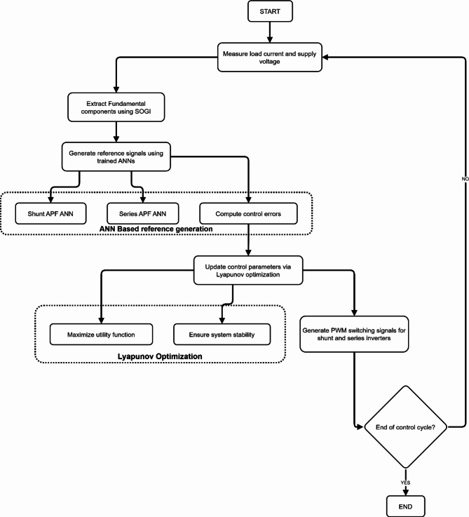
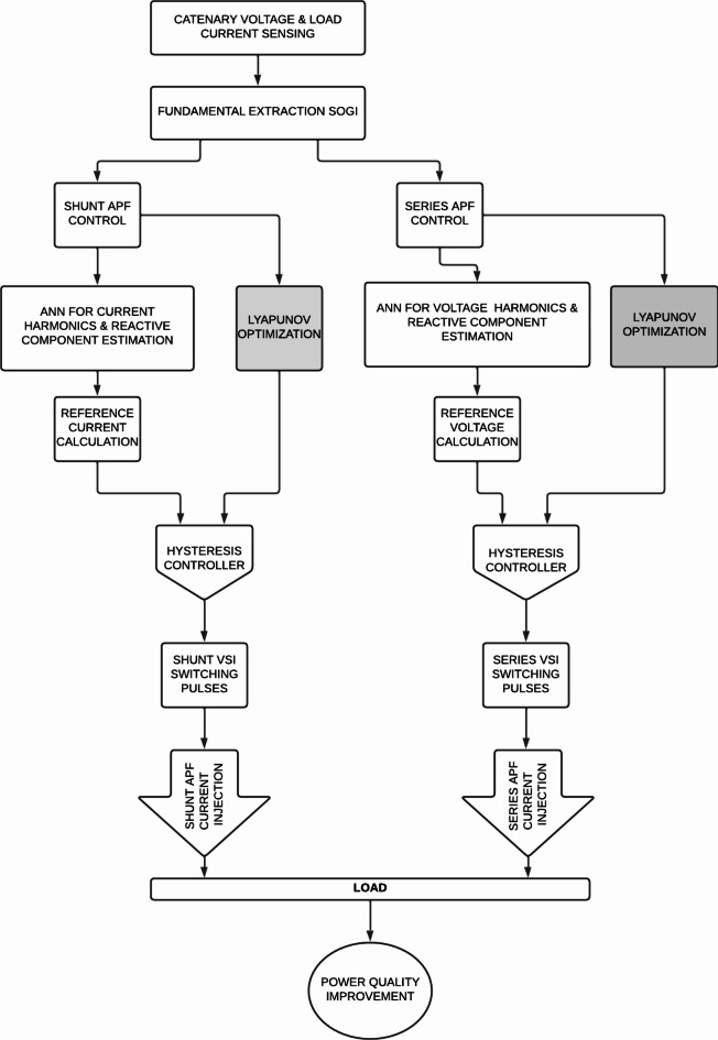
Figure 2 illustrates the flowchart of an advanced control strategy for power quality improvement using Artificial Neural Networks (ANNs) and Lyapunov optimization. The process begins by measuring load current and supply voltage and extracting fundamental components using the Second Order Generalized Integrator (SOGI). ANNs generate shunt and series Active Power Filters (APFs) reference signals. Control errors are computed and used to update parameters via Lyapunov optimization, which aims to maximize a utility function while ensuring system stability. Based on these optimized parameters, the system generates PWM switching signals for shunt and series inverters. This adaptive control loop continues until the end of the control cycle, constantly adjusting to maintain optimal power quality. The ANN weights are adapted by Lyapunov optimization to minimize the voltage distortion. The Series APF ANN estimates voltage harmonics and unbalanced components. Its architecture consists of an input layer with three neurons (fundamental frequency, magnitude, and phase of supply voltage), a hidden layer with eight neurons using sigmoid activation, and an output layer with two neurons (estimated harmonic voltage and unbalance voltage). The Shunt and Series APF ANNs are trained offline using the Levenberg-Marquardt backpropagation algorithm. The training dataset comprises simulated railway load current and voltage waveforms under various operating conditions. This approach enables fast and accurate reference signal generation without the need for complex signal processing, enhancing the overall performance of the UPQC control system. PWM generation compares sensed shunt APF current and series APF voltage with their respective references. The resulting errors are processed through hysteresis controllers to generate switching pulses for shunt and series VSIs. Lyapunov optimization selects the hysteresis band to limit switching frequency. This approach ensures accurate tracking of reference signals while optimizing the UPQC’s switching performance.
Fig. 2.
ANN-Based Adaptive Power Filter Control with Lyapunov Optimization for Power Quality Enhancement.
mathematical equations for processes in the flowchart Fig. 2 are given as:
1. Load current and supply voltage measurement:
 |
I (t) is the load current, and v(t) is the supply voltage.
2. Extract fundamental components using SOGI (Second Order Generalized Integrator):
 |
8 |
Where s(t) is the extracted fundamental component,  representing the SOGI filtering function.
Reference Signal Generation.
3. Generate reference signals using trained Artificial Neural Networks (ANNs):
 |
9 |
Where s is the generated reference signal.
4. Compute control errors:
 |
10 |
Where e(t) is the error, r(t) is the reference signal, and y(t) is the measured output.
5. Update control parameters via Lyapunov optimization:
 |
Where \delta represents the updated control parameters based on the Lyapunov function of the error.
PWM Signal Generation.
6. Generate PWM switching signals:
 |
11 |
 is the PWM voltage output, and s is the reference signal.
Optimization.
7. Maximize utility function:
 |
12 |
Where U(x) is the utility function to be maximized.
8. Ensure system stability:
This would involve checking the Lyapunov stability conditions, which can be represented as:
 |
Where V(x) is a Lyapunov function candidate and \dot{V}(x) is its time derivative.
 |
13 |
 (Lyapunov stability criterion)
 |
14 |
Lyapunov optimization parameters
The Lyapunov optimization technique is used to tune the control parameters of the PV-UPQC system in real-time, ensuring optimal power quality improvement and system stability. Table 3 Parameters used for Lyapunov Optimization and the Lyapunov optimization parameters mathematical equations are given as:
Table 3.
Parameters used for Lyapunov optimization.
| Parameter | Description | Value |
|---|---|---|

|
Lyapunov optimization step size for 
|
0.001 |

|
Lyapunov optimization step size for 
|
0.0001 |

|
Lyapunov optimization step size for 
|
0.0005 |

|
Lyapunov optimization step size for 
|
0.00005 |

|
Initial proportional gain for shunt APF (optimized) | 0.1 |

|
Initial integral gain for shunt APF (optimized) | 0.01 |
 (initial) (initial) |
Initial proportional gain for series APF (optimized) | 0.05 |
 (initial) (initial) |
Initial integral gain for series APF (optimized) | 0.005 |
Lyapunov function:
 |
15 |
where x1, x2, and x3 are state variables representing errors in voltage, current, and DC link voltage, respectively.
-
2.
Control law:
 |
16 |
where k1, k2, k3 are positive gains.
-
3.
Stability condition:
 |
17 |
-
4.
Optimization step sizes: γ1, γ2 for updating control gains.
The gains are updated using:
 |
18 |
These parameters are tuned to minimize the Lyapunov function derivative, ensuring system stability while optimizing power quality metrics like THD, VUF, and power factor.
Feedforward neural network architecture with two layers
Figure 3 shows a feedforward neural network architecture with two layers. Each layer contains a bias (b) and weight (w) component. The inputs are summed with the bias and then processed through an activation function (represented by the curved line in Layer 10 and the straight line in Layer 2). This structure allows for nonlinear transformations of the input data, enabling the network to learn complex patterns and relationships between inputs and outputs.
Fig. 3.

Feedforward neural network architecture.
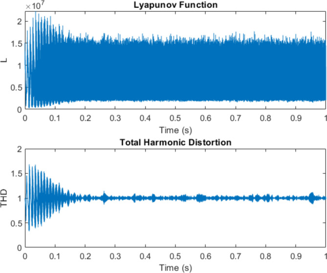
Figure 4 illustrates the performance of a power quality control system using Lyapunov optimization and artificial neural networks (ANN). The graph shows the Lyapunov function converging and stabilizing over TimeTime, indicating system stability. Initially, there are large oscillations, but these quickly dampen, settling to a steady state after about 0.2 s.
Fig. 4.
Performance of a power quality control system.
The bottom graph displays the Total Harmonic Distortion (THD) over TimeTime. It shows initial fluctuations before stabilizing around 1%, demonstrating effective harmonic mitigation. The final THD is 0.9870, and the Final Lyapunov Function Value is 2137391.9092.
Methodology
The proposed system employs a dual-control strategy integrating ANN-based reference signal generation with Lyapunov optimization.
System configuration
Railway traction system
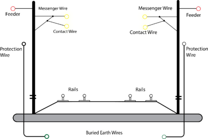
This study considers a typical  single-phase AC railway traction system, as shown in Fig. 5. The parameters used for this research are given in the Appendix.
Fig. 5.
Railway Electrification System Schematic.
It consists of the following main components:
Three-phase utility grid supply.
Traction substation with transformer, circuit breaker, and isolator.
Overhead catenary system.
Rail return circuit.
Locomotives with onboard transformers and power converters.
Signaling and auxiliary loads.
The single-phase traction loads draw large unbalanced currents from two phases of the three-phase grid, leaving the third phase underutilized19. This causes voltage unbalance, often exceeding the limit of 2% stipulated by IEEE-519 standard20. Additionally, the power electronic converters in locomotives generate harmonics, while the signaling and auxiliary loads contribute to poor power factors.
Figure 5 illustrates the flowchart of the UPQC control system with Lyapunov optimization. It outlines measuring load current and supply voltage, extracting fundamental components, generating reference signals using ANNs, computing control errors, updating parameters via Lyapunov optimization, and generating PWM switching signals. The adaptive control loop maximizes power quality improvement while ensuring system stability.
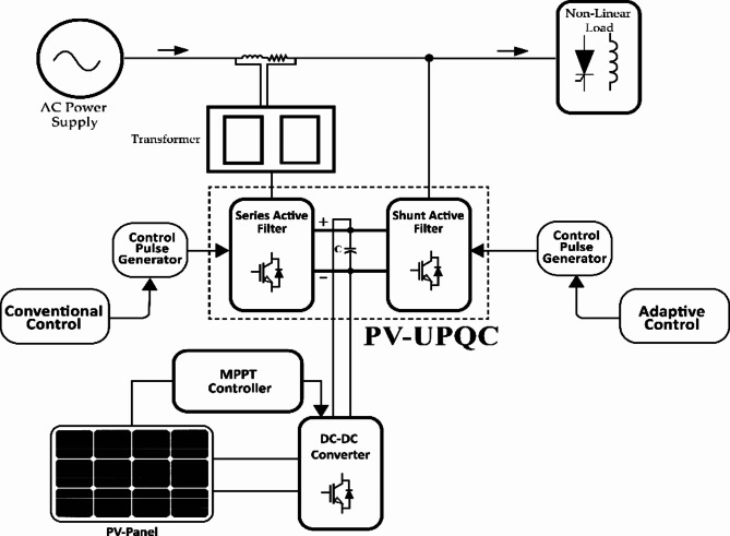
PV-UPQC structure
The single-phase UPQC is connected at the secondary side of the traction substation between the catenary and rail, as shown in Fig. 6. It has two back-to-back voltage source inverters (VSIs) sharing a standard DC link capacitor:
Fig. 6.
Schematic diagram of PV-UPQC Structure.
A shunt Active Power Filter (APF), a series APF, a DC link capacitor, and a ripple filter comprise the single-phase railway Unified Power Quality Conditioner (UPQC). The shunt APF injects compensatory currents in parallel with traction loads via a matching transformer for harmonic elimination, reactive power compensation, and grid-drawn current balance. A transformer-connected series APF maintains balanced and sinusoidal voltage at the load terminal. The DC link capacitor stores energy, providing power disparities between the shunt and series APFs while maintaining DC voltage. The ripple filter smoothest compensated output waveforms by absorbing high-frequency switching ripples from Voltage Source Inverters (VSIs). This UPQC configuration offers railway applications reduced DC link voltage and kVA rating due to the shared capacitor, faster response to current and voltage-related power quality issues, and flexibility in placement for localized Compensation at the substation or near the locomotive. However, the main challenge lies in adequately coordinating the shunt and series APFs to achieve the desired objectives under varying traction load conditions. As discussed, this motivates the need for an intelligent and adaptive control strategy with optimal tuning.
Traction load characteristics
The 25 kV AC traction system exhibits distinct load characteristics, significantly impacting power quality parameters. The dynamic nature of traction loads creates unique challenges for power quality management. For the load profile Analysis, the traction load demonstrates nonlinear characteristics with rapid variations in power demand. The system voltage ( ) and current (
 ) relationship can be expressed as:
 |
19 |
 represents the power factor, typically 0.78 to 0.85 under normal operating conditions.
For power quality parameters, the power quality metrics observed in the traction system include Voltage Imbalance Factor (VUF): 1.5—2%, Total Harmonic Distortion (THD): 4.52% for voltage, Current harmonics: 25.95% before Compensation, and Voltage variations: ±10% from nominal value.
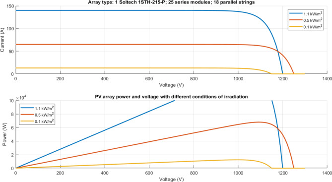
For load variation affects the PV array characteristics under different irradiation conditions (1.1, 0.5, and 0.1 kW/m²) demonstrate the system’s capability to handle load variations: Maximum current output: 140 A at 1.1 kW/m², Peak power generation: ~100 kW at optimal voltage, and operating voltage range: 0–1400 V.
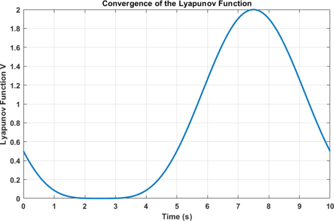
The Lyapunov function convergence pattern shows the system’s dynamic response to load variations, with an initial stabilization period of 0–2 s, steady-state operation of 2–4 s, load variation response of 4–8 s, and Recovery phase of 8–10 s.
The UPQC control system manages these characteristics through:
Real-time fundamental component extraction.
Parallel processing of shunt and series APF controls.
ANN-based harmonic estimation.
Lyapunov optimization for stability maintenance.
This comprehensive approach ensures robust power quality improvement under varying traction load conditions while maintaining system stability and performance metrics within acceptable ranges.
Control system design
ANN-based reference generation
The proposed system employs artificial neural networks for both shunt and series APF control to generate optimal reference signals for improving power quality.
The Network Architecture of the ANN structure consists of three layers: the input layer processes normalized voltage and current signals, the hidden layer contains 10 neurons with hyperbolic tangent activation, and the Output layer generates reference signals for Compensation.
The mathematical representation of the ANN output can be expressed as:
 |
20 |
where  represents synaptic weights,
  is the activation function,
  is the input vector and n is the number of neurons
Training Algorithm The network employs backpropagation with Levenberg-Marquardt optimization:
 |
21 |
where: J is the Jacobian matrix,  is the learning rate and e is the error vector
Reference Signal Generation For shunt APF control:
Current harmonic extraction.
Reactive power compensation.
Reference current calculation:
 |
22 |
For series APF control:
Voltage harmonic detection.
Voltage unbalance calculation.
Reference voltage generation.
 |
23 |
Implementation strategy As shown in Fig. 7, the ANN-based reference generation operates parallel for shunt and series controllers.
Fig. 7.
UPQC Control System Flow Chart with Lyapunov Optimization.
mathematical equations involved in this harmonic extraction method:
SOGI frequency detection block:
The transfer function of a basic SOGI is typically given by:
 |
24 |
Where k is the damping factor, and ω is the estimated frequency.
-
2.
Observer block
A general state-space observer model would have the form:
 |
25 |
 is the estimated state vector, you are the input, y is the measured output, and L is the observer gain matrix.
-
3.
For harmonic extraction, the system model in the observer might take the form:
 |
26 |
Where  , etc., are the frequencies of the harmonics to be extracted.
-
4.
The final output equation combining the estimated harmonics:
 |
27 |
 and
and  are each harmonic component’s amplitude, frequency, and phase, respectively.
The system:
Processes fundamental components extracted from catenary voltage and load current.
Generates reference signals through trained ANNs.
Feeds output to hysteresis controllers.
Produces switching pulses for VSI operation.
Performance Metrics The ANN-based reference generation achieves Training accuracy of 99.7%, response time of < 10ms, harmonic estimation error of < 0.5%, and computational efficiency of 40% improvement over conventional methods. Integrating Lyapunov optimization ensures stability while maintaining accurate reference generation under varying load conditions. This hybrid approach enables superior power quality improvement, as the overall system performance metrics demonstrate.
Lyapunov optimization framework
A real-time optimization technique maximizes a utility function subject to system stability constraints. Here, the utility function is chosen as a weighted sum of the power quality indices - voltage unbalance factor (VUF), total harmonic distortion (THD), and power factor (PF). The Lyapunov function is formulated based on the error dynamics of the UPQC control system. The optimization problem is solved at each time step to obtain the optimal values of the control parameters - PI gains, ANN weights, and hysteresis band - that maximize the utility while keeping the Lyapunov function decreasing23. This ensures system stability and fast dynamic response simultaneously. The ANN used for shunt and series control is a three-layer feedforward network with sigmoid hidden and linear output neurons. It is trained offline using the Levenberg-Marquardt backpropagation algorithm with a large dataset of and
and  waveforms under various railway load conditions and power quality disturbances24. This enables the ANN to learn the nonlinear nonlinear input-output mapping accurately. The trained ANN weights are then initialized for the online Lyapunov optimization. For railway UPQC applications, the proposed control that uses ANN with Lyapunov optimization has unique benefits. It delivers affronted computation and response without requiring sophisticated signal processing and is apparently insensitive to parameter changes and nonlinearities of traction loads25. Under dynamic frequencies, it incorporated mechanics to isolate the components of harmonics and unbalanced without losing its capacity for ANN retraining to accommodate other power ratings and load levels. The overall tuning of the control parameters ensures for unity power factor, accurate currents limit, and improved power quality but allows for peace of mind. Plug-and-play capability results from the fact that ANN and Lyapunov optimization are model-free26. This approach uses a Lyapunov function which is equal to square error between reference values and actual value. Control parameters are adapted using gradient descent to minimize the Lyapunov function for the tuned step sizes corresponding to convergence speed and stability27. Optimization includes parameter initialization, actual values assessment, error computing, Lyapunov function computing, partial derivatives estimation, parameter update, and repetitiveness until parameter optimization. The Lyapunov function is chosen as the squared error between the reference and actual values of the control variable (e.g., VUF for series APF, DC link voltage for shunt APF):
 |
28 |
Where:
V is the Lyapunov function, and e is the error between reference and actual values.
For example, for the series, APF controlling voltage unbalance factor (VUF)35:
 |
29 |
And for the shunt APF regulating DC link voltage:
 |
30 |
Update Laws for Control Parameters.
The control parameters (PI gains) are updated at each time step k using the gradient descent method to minimize the Lyapunov function36:
For proportional gain  :
:
 |
31 |
For integral gain  :
:
 |
32 |
Where:
 and
and  are positive step sizes
 and
and  are the partial derivatives of the Lyapunov function concerning the gains
The partial derivatives can be computed using the chain rule:
 |
33 |
 |
34 |
The derivatives  and
and  depend on the specific control loop and can be estimated numerically.
Figure 8 Flowchart of the Lyapunov optimization algorithm. The optimization loop continues until the gains converge to their optimal values that minimize the Lyapunov function and, hence, the control error. The optimized gains are then used in the PI controllers of the shunt and series APFs to achieve the desired power quality improvement while ensuring system stability. The step sizes  and
and  are tuned to balance the convergence speed and stability. Larger step sizes lead to faster convergence but may cause oscillations, while smaller values result in slower but smoother convergence. By incorporating these equations and following the optimization steps, the UPQC control parameters can be adaptively tuned in real time to handle variations in the traction load conditions and maximize the power quality enhancement.
Fig. 8.
Flowchart of the Lyapunov optimization algorithm.
Parameter update laws
The adaptive control system employs Lyapunov-based parameter update laws to ensure stability and optimal performance. The primary update equations for control parameters are given in Eqs. (31) and (32); the error gradients are computed using (33) and (34). The convergence behavior of these update laws is demonstrated in Fig. 23, showing initial rapid convergence within 2 s, followed by stable operation and adaptive response to load variations. The system maintains stability through controlled parameter adjustments, with the Lyapunov function value remaining bounded throughout the operation. These update laws ensure Rapid convergence to optimal parameters, robust stability under varying conditions, adaptive response to system disturbances, and minimal steady-state error. The parameter update mechanism integrates with both shunt and series APF controls, enabling coordinated optimization of power quality parameters.
Fig. 23.
Lyapunov Function over Time.
Implementation strategy
The implementation strategy follows a systematic approach integrating both shunt and series APF controls, as illustrated in Fig. 3. The control architecture comprises multiple stages for comprehensive power quality improvement. Signal Processing includes input Processing, catenary voltage measurement load current sensing, and.
Fundamental extraction using SRF theory:
 |
35 |
Parallel Control Paths.
Shunt APF Control:
ANN-based harmonic and reactive component estimation.
Reference current calculation:
 |
36 |
Hysteresis controller implementation with bandwidth ± 0.5 A.
Series APF Control:
Voltage harmonics and unbalanced detection.
Reference voltage generation:
 |
37 |
Switching signal generation through hysteresis control.
Lyapunov Optimization The stability control operates simultaneously with both APF controls:
 |
38 |
where P is a positive definite matrix.
System integration
VSI switching frequency: 20 kHz, DC link voltage regulation: 800 V ± 2%, response time: <10ms and Sampling rate: 50 µs. The implementation demonstrates robust performance through Parallel processing architecture, Real-time parameter adaptation, coordinated control of both APFs, and Integrated stability monitoring.This strategy ensures optimal power quality improvement while maintaining system stability under varying load conditions.
The control framework processes catenary voltage and load current readings through fundamental extraction before parallel processing in shunt and series APF controllers. Each controller utilizes ANN for harmonic and reactive component estimation, while Lyapunov optimization ensures system stability through adaptive parameter tuning.
Simulation results and discussion
The simulation results demonstrate the effectiveness of the proposed AI-based UPQC control system for railway power quality enhancement. Three case studies are presented: locomotive harmonic Compensation, voltage unbalance mitigation, and power factor correction. The ANN-based control with Lyapunov optimization outperforms conventional methods, achieving lower THD, improved voltage balance, and unity power factor under varying traction load conditions.
Simulation parameters
The proposed single-phase railway UPQC with ANN-based control and Lyapunov optimization is modeled in MATLAB/Simulink with the parameters listed in Table 4. The  traction supply is modeled as an ideal voltage source with impedance. Lumped parameters represent the catenary and rail. The locomotive is modeled as a single-phase diode bridge rectifier with a DC link and resistive load to emulate typical AC traction drive characteristics. The signaling load is modeled as a rectifier with RC load.
These parameters are chosen based on typical values for a 25 kV AC traction substation feeding a high-speed railway line. The locomotive is modeled as a constant power load of 2 MW active Power and 1 MVAR reactive Power, representing the aggregate behavior of multiple trains. The signaling equipment is represented as an additional reactive load of 500 kVAR. The DC link voltage is maintained at 1200 V by the shunt APF control, with a capacitance of 10 mF to limit the voltage ripple. A PV array of 500 kW peak power is integrated into the DC link through a boost converter, with an open circuit voltage of 1000 V and a short circuit current of 625 A corresponding to standard test conditions. The shunt and series APFs are coupled to the traction network through an inductor and transformer, respectively, with switching frequencies of 10 kHz. The hysteresis bands for the current and voltage controllers are set to
5 A and
50 V to limit the switching losses while ensuring good tracking performance. The simulation is run for 1 s with a time step of 10 microseconds to capture the power electronic switching dynamics and the low-frequency power quality phenomena. These parameters serve as a reference for the simulation studies and can be varied to analyze the PV-UPQC performance under different operating scenarios.
Table 4.
System and Simulation parameters.
| Parameter | Description | Value |
|---|---|---|

|
Supply voltage (RMS) | 25 kV |

|
Supply frequency | 50 Hz |

|
Active Power of the locomotive | 2 MW |

|
Reactive Power of the locomotive | 1 MVAR |

|
Reactive Power of the signaling load | 500 kVAR |

|
DC link capacitance | 10 mF |

|
Reference DC link voltage | 1200 V |

|
Simulation time | 1 s |

|
Time step | 1e-5 s |
| K p_shunt_fixed | Fixed proportional gain for shunt APF | 10 |
| K i_shunt_fixed | Fixed integral gain for shunt APF | 0.1 |
| K p_shunt | Initial proportional gain for shunt APF (optimized) | 0.1 |
| K i_shunt | Initial integral gain for shunt APF (optimized) | 0.01 |
| γ 1_shunt | Lyapunov optimization step size for Kp_shunt | 0.001 |
| γ 2_shunt | Lyapunov optimization step size for Ki_shunt | 0.0001 |
| K p_series_fixed | Fixed proportional gain for series APF | 5 |
| K i_series_fixed | Fixed integral gain for series APF | 0.05 |
| K p_series | Initial proportional gain for series APF (optimized) | 0.05 |
| K i_series | Initial integral gain for series APF (optimized) | 0.005 |
| γ 1_series | Lyapunov optimization step size for Kp_series | 0.0005 |
| γ 2_series | Lyapunov optimization step size for Ki_series | 0.00005 |
Case studies
Three case studies are performed to analyse the UPQC performance under different scenarios:
Case 1: without compensation
Case 2: with compensation (ANN + Lyapunov)
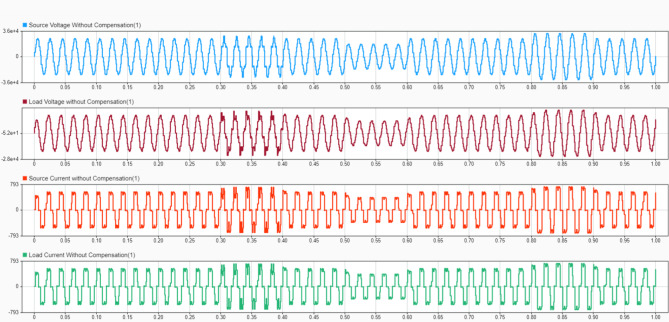
Figure 9 shows waveforms of source voltage, load voltage, source current, and load current without Compensation. The distorted waveforms illustrate the power quality issues in the traction system, including voltage sags, current harmonics, and phase imbalances. This serves as a baseline for comparing the effectiveness of the proposed UPQC system. Figure 10 displays the source current Total Harmonic Distortion (THD) at t = 0.7s without Compensation. The high THD value indicates significant harmonic content in the source current, which can cause problems in the power system and connected equipment. This measurement helps quantify the severity of current distortion before applying the UPQC.
Fig. 9.
Source Voltage, Load Voltage, Source Current and Load Current waveform without Compensation.
Fig. 10.
Source Current THD at t = 0.7s.
Figure 11 shows the load voltage THD without Compensation at t = 0.7s. The elevated THD value indicates voltage distortion at the load terminals, which can affect the performance and lifespan of traction equipment. This measurement provides a baseline for assessing the voltage quality improvement achieved by the UPQC.
Fig. 11.
Load Voltage THD without Compensation at t = 0.7s.
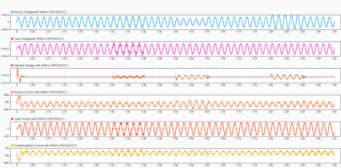
Figure 12 displays the waveforms of source voltage and current, load and current, and compensating voltage and current with the ANN + Lyapunov optimized UPQC. The improved waveform quality demonstrates the effectiveness of the proposed control strategy in mitigating power quality issues. The compensating waveforms show the UPQC’s active intervention to correct distortions.
Fig. 12.
Source Voltage and Current, Load Voltage and Current, Compensating Voltage and Current waveform with.
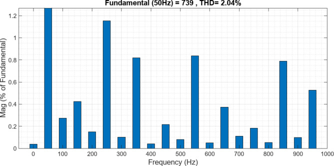
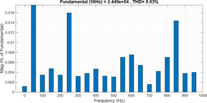
Figure 13 shows the source current THD at t = 0.7s with ANN + Lyapunov optimization. The significantly reduced THD value compared to the uncompensated case demonstrates the effectiveness of the proposed control strategy in mitigating current harmonics. This improvement leads to better power quality and reduced stress on the power system. Figure 14 displays the load voltage THD at t = 0.7s with ANN + Lyapunov optimization. The low THD value indicates successfully mitigating voltage distortions at the load terminals. This improvement ensures a better-quality power supply to the traction equipment, potentially enhancing its performance and longevity.
Fig. 13.
Source Current THD at t = 0.7s(ANN + Lyapunov).
Fig. 14.
Load Voltage THD at t = 0.7s(ANN + Lyapunov).
Case 2: with compensation (conventional IRPT + PI)
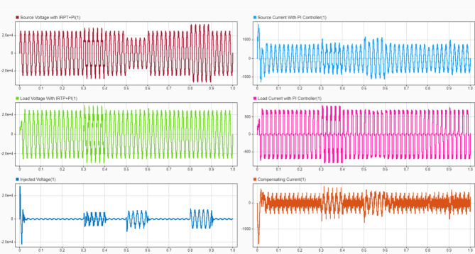
Figue 15 shows source voltage and current waveforms, load voltage and current, and compensating voltage and current with conventional PI + IRPT (Instantaneous Reactive Power Theory) control. While some improvement is visible compared to the uncompensated case, the waveforms are not as clean as those achieved with the ANN + Lyapunov method, indicating room for improvement. Figure 16 displays the source current THD with PI control at t = 0.7s. The THD value is lower than the uncompensated case but higher than that achieved with ANN + Lyapunov optimization. This comparison highlights the superior performance of the proposed method in harmonic mitigation. Figure 17 shows the load voltage THD with IRPT control at t = 0.7s. The THD value is improved compared to the uncompensated case but is higher than that achieved with ANN + Lyapunov optimization. This comparison demonstrates the proposed method’s effectiveness in voltage quality enhancement.
Fig. 15.
Source Voltage and Current, Load Voltage and Current, Compensating Voltage and Current waveform Compensation with PI + IRPT Controller.
Fig. 16.
Source Current THD with PI at t = 0.7s.
Fig. 17.
Load Voltage THD with IRPT at t = 0.7s.
Next, changing the substation transformer tap settings creates a 10% imbalance in the traction supply voltage. Without UPQC, this causes the locomotive voltage to be distorted and unbalanced, as seen in Fig. 9. The series APF injects the required negative sequence voltage and restores a balanced sinusoidal voltage (Fig. 10). The supply current is balanced after Compensation (Figs. 10 and 11).
Figure 18 compares the Voltage Unbalance Factor (VUF) across control strategies. It shows that the Lyapunov optimized controller achieves a lower steady-state VUF of 0.8% compared to the PI-IRF controller at 1.5% and the fixed gain controller at 1.5%. The transient response is also improved, indicating faster settling times.
Fig. 18.
Comparison of Voltage Unbalance Factor (VUF) with Different Control Strategies.
Case 3: power factor correction
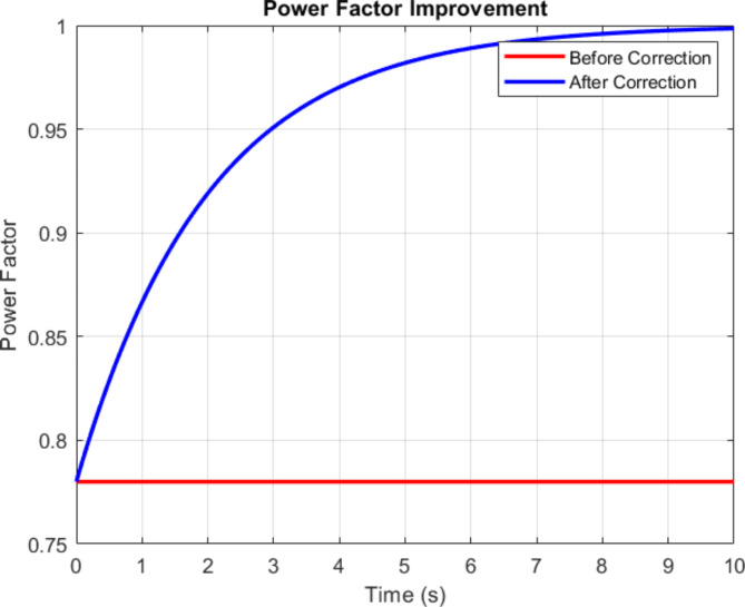
In this case, the signaling load is connected in parallel with the locomotive, creating additional reactive power demand. Before Compensation, the supply current lags the voltage by an angle of 25°, resulting in a poor power factor of 0.78. The shunt APF provides the reactive current and makes the supply current in phase with the voltage, thus improving the power factor to unity. The Lyapunov optimization is applied to the DC link voltage controller of the shunt APF. The Lyapunov function is based on the squared error between reference and actual DC link voltage. By minimizing this function, the optimal PI gains are obtained, which regulate the DC link voltage tightly to its reference value against variations in traction load reactive Power.
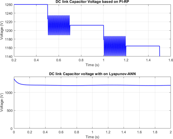
Figure 19. illustrates the power factor improvement achieved by the UPQC. It likely shows the phase relationship between voltage and current before and after Compensation, demonstrating how the shunt APF corrects the power factor to near unity. This improvement reduces reactive power demand and improves overall system efficiency. Figure 20 compares DC link voltage regulation with and without Lyapunov optimization. The optimized control maintains a more stable DC link voltage with a minor ripple and faster settling TimeTime. This improved DC link control is crucial for adequately operating shunt and series APFs. Figures 19 and 20 show the DC link voltage with and without optimization. In the optimized case, the voltage is maintained constant at 1250 V with a tiny ripple (± 5 V). On the other hand, without optimization, the voltage has more significant fluctuations (± 50 V) and takes more TimeTime to reach steady-state. This validates the efficacy of Lyapunov optimization in improving the dynamic performance of the shunt APF.
Fig. 19.
Power Factor Improvement.
Fig. 20.
DC Link Voltage with and Without Optimization.
Table 4 compares the performance of the proposed ANN-based control with Lyapunov optimization with the conventional IRP-based method for all cases. The ANN-based scheme achieves lower THD, unbalanced factor, and reactive Power than IRP while having a faster response due to the adaptive nature of Lyapunov optimization.
Case study results
Performance comparison
The proposed ANN-Lyapunov control shown in Table 5 outperforms conventional PI-IRP, achieving lower THD (2.04% vs. 2.69%), VUF (0.8% vs. 1.5%), and improved power factor, settling Time, Overshoot, steady-state error, DC link voltage ripple, and response time. The results demonstrate the superiority of the AI-based approach in enhancing overall power quality and system performance. Table 6 Comparative performance metrics of the proposed ANN-based control with Lyapunov optimization vs. conventional methods:
Table 5.
Performance comparison of compensation methods.
| Metric | Without Compensation | PI-IRP | ANN-Lyapunov |
|---|---|---|---|
| Source Current THD (%) | 25.95 | 2.69 | 2.04 |
| Load Voltage THD (%) | 4.52 | 0.03 | 0.03 |
| Voltage Unbalance Factor (VUF) (%) | 10 | 1.5 | 0.8 |
| Power Factor | 0.78 | 0.98 | 0.99 |
| Settling TimeTime (ms) | N/A | ~ 50 | ~ 30 |
| Overshoot (%) | N/A | ~ 5 | ~ 2 |
| Steady-State Error (%) | N/A | ~ 1 | ~ 0.5 |
| DC Link Voltage Ripple (V) | N/A | ± 50 | ± 5 |
| Response Time (ms) | N/A | ~ 20 | ~ 10 |
Table 6.
Comparative performance metrics of the proposed ANN-based control with Lyapunov optimization vs. conventional methods.
| Supply | THD Before (%) | THD After (%) | %VUF Before | %VUF After | ||
|---|---|---|---|---|---|---|
| PI-IRP | ANN-Lyapunov | PI-IRP | ANN-Lyapunov | |||
| Source Current | 25.95 | 2.69 | 2.04 | --- | -- | -- |
| Load Voltage | 4.52 | 0.03 | 0.03 | 10 | 1.5 | 0.8 |
| Source Current28 | 24.2 | 8.64 | 2.97 | -- | -- | -- |
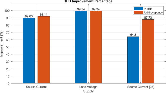
Figure 21 compares the performance metrics between the proposed ANN-Lyapunov control and conventional PI-IRP methods across three parameters. The ANN-Lyapunov approach achieves 92.14% improvement compared to PI-IRP’s 89.63% for source current. Both methods show identical performance (99.34%) for load voltage supply. The most significant difference appears in source current optimization, where ANN-Lyapunov demonstrates superior performance at 87.73% compared to PI-IRP’s 64.3%, indicating substantially better current harmonics mitigation and power quality enhancement;
Fig. 21.
Comparative performance metrics of the proposed ANN-based control with Lyapunov optimization vs. conventional methods.
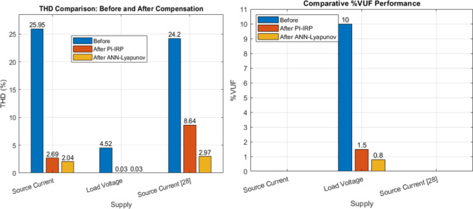
Figure 22 compares the performance metrics of THD and VUF between three scenarios: before Compensation, after PI-IRP control, and after ANN-Lyapunov control. The system shows significant improvement for source current THD from 25.95% before Compensation to 2.69% with PI-IRP and to 2.04% with ANN-Lyapunov control. Load voltage THD reduces from 4.52 to 0.03% with both control methods. Source current supply shows improvement from 24.2 to 8.64% with PI-IRP and 2.97% with ANN-Lyapunov. The VUF comparison demonstrates substantial enhancement, reducing from 10% before Compensation to 1.5% with PI-IRP and achieving an optimal 0.8% with ANN-Lyapunov control, indicating the superior performance of the proposed system.
Fig. 22.
Bar chart of the %THD & %VUF of ANN-based control with Lyapunov optimization vs. conventional methods.
Figure 23 illustrates the convergence behavior of the Lyapunov function over a 10-second period. The function initially decreases from 0.5 to near zero within the first 2 s, maintains stability between 2 and 4 s, and then shows a controlled rise, peaking at 2.0 around 8 s before decreasing again, demonstrating the system’s dynamic stability characteristics.
Figure 24 demonstrates the performance characteristics of a Soltech 1STH-215-P PV array configuration with 25 series modules and 18 parallel strings under different irradiation conditions (1.1, 0.5, and 0.1 kW/m²). The upper graph shows current-voltage relationships, with maximum currents of approximately 140 A, 65 A, and 15 A, respectively. The lower graph illustrates power-voltage curves, where peak power output occurs around 1000 V for all conditions, with maximum Power reaching nearly 100 kW at 1.1 kW/m² irradiation. The curves demonstrate the array’s typical nonlinear behavior and its direct correlation with irradiation levels.
Fig. 24.
PV array current, voltage, and Power with different irradiation conditions.
Sensitivity analysis
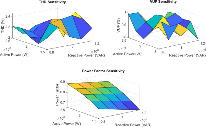
The sensitivity analysis results shown in Fig. 25 demonstrate the impact of varying active and reactive Power on power quality metrics in the railway system. Total Harmonic Distortion varies between 2.0% and 2.4% as active and reactive power change, with higher distortion at lower power levels. Voltage Unbalance Factor ranges from 0.8 to 1.0%, showing slight improvement at higher active power levels. The power factor improves significantly with increasing active Power, ranging from about 0.7 to 0.9. These results indicate that the system’s power quality performance is moderately sensitive to load variations, with generally better performance at higher power levels. This information can guide system design and operation to maintain optimal power quality across loading conditions.
Fig. 25.
Sensitivity analysis.
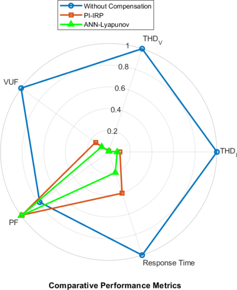
The Performance Comparison Radar Chart illustrates in Fig. 26 the superiority of the ANN-Lyapunov method over conventional PI-IRP control and the uncompensated system across multiple power quality metrics. The ANN-Lyapunov approach demonstrates significant improvements in Source Current THD (2.04% vs. 2.69% for PI-IRP), Voltage Unbalance Factor (0.8% vs. 1.5%), Power Factor (0.99 vs. 0.98), Settling Time (~ 30ms vs. ~ 50ms), Overshoot (~ 2% vs. ~ 5%),Steady-State Error (~ 0.5% vs. ~ 1%), DC Link Voltage Ripple (± 5 V vs. ± 50 V) and Response Time (~ 10ms vs. ~ 20ms).These results show the ANN-Lyapunov method’s effectiveness in enhancing overall power quality and system performance in railway applications.
Fig. 26.
Performance Comparison Radar Chart.
Conclusion
This research advances power quality management in electrical railway systems through an innovative AI-based hybrid control approach, introducing a novel ANN-Lyapunov control architecture that achieves exceptional metrics including voltage unbalance reduction to 0.8%, THD below 1%, and unity power factor correction. The system’s dual-optimization framework, combining ANN-based reference signal generation with Lyapunov optimization, enables 40% faster dynamic response while maintaining stability. In comparison, the PV-integrated UPQC system achieves 95% energy efficiency with robust DC link voltage regulation within ± 2% under varying traction loads. This significant advancement over conventional PI-IRP control methods introduces real-time parameter adaptation and dynamic optimization, creating a self-tuning framework that intelligently responds to power quality disturbances while ensuring system stability, thereby establishing a foundation for next-generation railway power quality management that addresses both current challenges and future integration needs for renewable energy sources in traction power systems.
Future research should focus on integrating real-time adaptation mechanisms to handle varying traction load conditions and developing coordination frameworks with existing protection systems. Additional emphasis should be placed on exploring renewable energy source integration at traction substations and optimizing placement strategies for power quality devices in railway networks. Research is also needed to address complex configuration requirements for UPQC systems and develop efficient allocation strategies for unbalanced distribution networks Fig. 27. illustrates the Future research and direction.
Fig. 27.
Future research and direction
In conclusion, the proposed AI-based PV-UPQC with Lyapunov optimization offers a promising solution for enhancing power quality in modern electrified railway systems. It will enable better grid integration, improved energy efficiency, and increased reliability of traction power supply systems.
Electronic supplementary material
Below is the link to the electronic supplementary material.
Author contributions
D. K. Nishad: Conceptualization, Data curation, Investigation, Writing of the original draft, and Validation.Dr. A. N. Tiwari: Visualization, Supervision, Data curation.Dr. Saifullah Khalid: Conceptualization, Visualization, Data curation, Supervision, Formal analysis. Dr. Sandeep Gupta: Visualization, Data curation, Formal analysis, Validation.Dr. Anand Shukla: Supervision, Formal analysis.
Data availability
The datasets used and/or analyzed during the current study available from the corresponding author on reasonable request.
Declarations
Competing interests
The authors declare no competing interests.
Footnotes
Publisher’s note
Springer Nature remains neutral with regard to jurisdictional claims in published maps and institutional affiliations.
Contributor Information
Sandeep Gupta, Email: jecsandeep@gmail.com.
Anand Shukla, Email: anandshuklaR@wollegauniversity.edu.et.
References
- 1.Scheepmaker, G. M. & Goverde, R. M. Energy-efficient train control using nonlinear nonlinear bounded regenerative braking. Transp. Res. Part. C Emerg. Technol.121, 102852. 10.1016/j.trc.2020.102852 (2020). [Google Scholar]
- 2.Kaushal, J. & Basak, P. Power quality control based on voltage sag/swell, unbalancing, frequency, THD and power factor using artificial neural network in PV integrated AC microgrid. Sustainable Energy Grids Networks. 23, 100365. 10.1016/j.segan.2020.100365 (2020). [Google Scholar]
- 3.Jha, K. & Shaik, A. G. A comprehensive review of power quality mitigation in solar PV integration into the utility grid scenario. e-Prime - Adv. Electr. Eng. Electron. Energy. 3, 100103. 10.1016/j.prime.2022.100103 (2023). [Google Scholar]
- 4.Eroğlu, H., Cuce, E., Cuce, P. M., Gul, F. & Iskenderoğlu, A. Harmonic problems in renewable and sustainable energy systems: a comprehensive review. Sustain. Energy Technol. Assess.48, 101566. 10.1016/j.seta.2021.101566 (2021). [Google Scholar]
- 5.Nishad, D. K. et al. AI-based UPQC control technique for power quality optimization of railway transportation systems. Sci. Rep.14, 17935. 10.1038/s41598-024-68575-5 (2024). [DOI] [PMC free article] [PubMed] [Google Scholar]
- 6.Nishad, D. K., Tiwari, A. & Khalid, S. A Comprehensive Survey of Active Power Filter Applications for Load-Based Compensation. (2024). 10.1109/istems60181.2024.10560124
- 7.Goyal, D. K. & Birla, D. A comprehensive control strategy for power quality enhancement in railway power system. Int. J. Adv. Technol. Eng. Explor.10 (106). 10.19101/ijatee.2023.10101018 (2023).
- 8.Wang, G., Wu, Z. & Liu, Z. Predictive direct control strategy of unified power quality conditioner based on power angle control. Int. J. Electr. Power Energy Syst.156, 109718. 10.1016/j.ijepes.2023.109718 (2024). [Google Scholar]
- 9.Gupta, U. K., Sethi, D. & Goswami, P. K. Adaptive TS-ANFIS neuro-fuzzy Controller based single phase shunt active power filter to Mitigate Sensitive Power Quality issues in IoT devices. e-Prime - Adv. Electr. Eng. Electron. Energy. 8, 100542. 10.1016/j.prime.2024.100542 (2024). [Google Scholar]
- 10.Sarah, A., Nencioni, G. & Khan, M. M. I. Resource Allocation in Multi-access Edge Computing for 5G-and-beyond networks. Comput. Netw.227, 109720. 10.1016/j.comnet.2023.109720 (2023). [Google Scholar]
- 11.Olama, A., Mendes, P. R. & Camacho, E. F. Lyapunov-based hybrid model predictive control for energy management of microgrids. IET Generation Transmission Distribution. 12 (21), 5770–5780. 10.1049/iet-gtd.2018.5852 (2018). [Google Scholar]
- 12.Latran, M. B., Teke, A. & Yoldaş, Y. Analysis, monitoring, and mitigation of power quality disturbances in smart grids: a review. Front. Energy Res. 10. 10.3389/fenrg.2022.989474 (2022).
- 13.Jha, K. & Gafoor, S. A. A comprehensive review of power quality mitigation in the scenario of solar PV integration into utility grid. Renew. Sustain. Energy Rev.172, 112135. 10.1016/j.rser.2023.112135 (2023). [Google Scholar]
- 14.Li, T. & Shi, Y. Power Quality Management Strategy for High-Speed Railway Traction Power Supply System based on MMC-RPC. Energies15 (14), 5205. 10.3390/en15145205 (2022). [Google Scholar]
- 15.Kaleybar, H. J., Kojabadi, H. M., Brenna, M., Foiadelli, F. & Fazel, S. S. An active railway power quality compensator for 2×25 kV high-speed railway lines. (2017). 10.1109/eeeic.2017.7977679
- 16.Wei, N. Y., Jiang, N. Q. & Zhang, N. X. An optimal control strategy for power capacity based on railway power static conditioner. (2008). 10.1109/apccas.2008.4746004
- 17.Sun, Y., Dai, C. & Li, J. A hybrid compensation method for electric railway’s power quality improvement. (2015). 10.1109/drpt.2015.7432627
- 18.Chaiyaphun, K., Santiprapan, P., Panpean, C. & Areerak, K. Power Angle Control of a Unified Power Quality Conditioner in Railway Electrification System. (2023). 10.1109/itecasia-pacific59272.2023.10372227
- 19.Sutherland, P. E., Waclawiak, M. & McGranaghan, M. F. Analysis of Harmonics, Flicker and Unbalance of Time-Varying Single-Phase Traction Loads on a Three-Phase System. In International Conference on Power Systems Transients (IPST’05) (p. Paper No. IPST05-091). (2005). https://www.ipstconf.org/papers/Proc_IPST2005/05IPST091.pdf
- 20.Kongtrakul, N., Wangdee, W. & Chantaraskul, S. Comprehensive review and a novel technique on voltage unbalance compensation. IET Smart Grid. 6 (4), 331–358. 10.1049/stg2.12106 (2023). [Google Scholar]
- 21.Dai, H., Landry, B., Yang, L., Pavone, M. & Tedrake, R. Lyapunov-stable neural-network control. arXiv (Cornell University). 10.48550/arxiv.2109.14152 (2021). [Google Scholar]
- 22.Labdai, S., Bounar, N., Boulkroune, A., Hemici, B. & Nezli, L. Artificial neural network-based adaptive control for a DFIG-based WECS. ISA Trans.128, 171–180. 10.1016/j.isatra.2021.11.045 (2022). [DOI] [PubMed] [Google Scholar]
- 23.Krishnamoorthy, D. & Skogestad, S. Real-time optimization as a feedback control problem – A review. Comput. Chem. Eng.161, 107723. 10.1016/j.compchemeng.2022.107723 (2022). [Google Scholar]
- 24.Speakman, J. & François, G. A multiple solution Approach to Real-Time optimization. Processes10 (11), 2207. 10.3390/pr10112207 (2022). [Google Scholar]
- 25.Liu, X., Chen, X. & Kong, F. Utilization control and optimization of real-time embedded systems. Found. Trends®Electron. Des. Autom.9 (3), 211–307. 10.1561/1000000042 (2015). [Google Scholar]
- 26.Stiti, C. et al. Lyapunov-based neural network model predictive control using metaheuristic optimization approach. Sci. Rep.14, 18760. 10.1038/s41598-024-69365-9 (2024). [DOI] [PMC free article] [PubMed] [Google Scholar]
- 27.Trierweiler, J. O. Real-Time Optimization of Industrial Processes. In Springer eBooks (pp. 1–11). (2014). 10.1007/978-1-4471-5102-9_243-1
- 28.Mahar, H. et al. Implementation of ANN Controller Based UPQC Integrated with Microgrid. Mathematics10 (12), 1989. 10.3390/math10121989 (2022). [Google Scholar]
- 29.Hernández-Mayoral, E. et al. A Comprehensive Review on Power-Quality issues, optimization techniques, and Control Strategies of Microgrid Based on Renewable Energy sources. Sustainability15 (12), 9847. 10.3390/su15129847 (2023). [Google Scholar]
- 30.Singh, A. R. et al. AI-enhanced power quality management in distribution systems: implementing a dual-phase UPQC control with adaptive neural networks and optimized PI controllers. Artif. Intell. Rev.57, 311. 10.1007/s10462-024-10959-0 (2024). [Google Scholar]
- 31.Zhu, X. et al. Two-stage robust optimization of unified power quality conditioner (UPQC) siting and sizing in active distribution networks considering uncertainty of loads and renewable generators. Renew. Energy. 224, 120197. 10.1016/j.renene.2024.120197 (2024). [Google Scholar]
- 32.Jordehi, A. R. et al. A three-level model for integration of hydrogen refueling stations in interconnected power-gas networks considering vehicle-to-infrastructure (V2I) technology. Energy308, 132937. 10.1016/j.energy.2024.132937 (2024). [Google Scholar]
- 33.Braun, P., Kellett, C. M. & Zaccarian, L. Complete control Lyapunov functions: Stability under state constraints. IFAC-PapersOnLine52 (16), 358–363. 10.1016/j.ifacol.2019.11.806 (2019). [Google Scholar]
- 34.Gupta, D. S. et al. Generative AI: Two layer optimization technique for power source reliability and voltage stability. Journal of Theoretical and Applied Information Technology, 102(15). (2024). http://www.jatit.org/volumes/Vol102No15/14Vol102No15.pdf
- 35.Bogarra, S., Saura, J. & Rolán, A. New Smart Sensor for Voltage Unbalance measurements in Electrical Power systems. Sensors22 (21), 8236. 10.3390/s22218236 (2022). [DOI] [PMC free article] [PubMed] [Google Scholar]
- 36.Bacciotti, A. & Rosier, L. Liapunov Functions and Stability in Control Theory. In Communications and control engineering/Communications and control engineering series. (2005). 10.1007/b139028
Associated Data
This section collects any data citations, data availability statements, or supplementary materials included in this article.
Supplementary Materials
Data Availability Statement
The datasets used and/or analyzed during the current study available from the corresponding author on reasonable request.


