

Abstract
This article explores the crucial function that Shell and Tube Heat Exchangers (STHE) play in a variety of industrial applications. This research uses a three-dimensional computational fluid dynamics (CFD) simulation to model turbulent fluid flow and evaluate the performance of different baffle angle configurations. The study evaluates performance indicators such as overall heat transfer coefficient (OHT), shell side heat transfer coefficient (HTC), pressure drop (PD), and PEC (Performance Evaluation Criteria), this study evaluates their effect on Segmental STHE performance. The findings indicate that the PD in the shell section rises by a range of 56.8–60.9% for baffles inclined 0° to 30°. Additionally, compared to the 0° inclined baffles, the 30° inclined baffles exhibit a greater OHT of 4.5–6%. The PEC values that are determined for each type of baffle are the most crucial aspect to take into account while selecting the optimal STHE. The 25° inclined baffles have been selected as the most advantageous baffles due to their improved performance, as seen by their different PEC values. In the subsequent stage of the study, researchers investigated how changing the quantity of superior baffles (inclined) affects the STHE’s efficiency. As the number of baffles was increased from 4 to 10, the OHT rose by 14.5–17% and the PD increased by 138.63–141.7%. This thorough simulation revealed that the STHE with the 8 inclined baffles had the highest PEC value and was therefore the most appropriate STHE.
Keywords: Segmental baffle, Inclined baffles, Baffle numbers, Shell and tube heat exchangers
Subject terms: Engineering, Mechanical engineering
Introduction
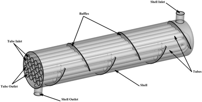
Heat exchangers are now extensively utilized in industrial settings and are essential components in all thermal systems. Among these, the shell and tube design is the most frequently employed type1. Due to their small size and ability to transfer huge volumes of heat quickly, heat exchangers are employed in the majority of engineering applications, The performance of a heat exchanger depends on its design, the thermophysical properties of the fluid it uses, and the enhancement techniques applied2. The typical configuration of STHEs features cylindrical tubes arranged within a circular shell; to transfer heat, different-temperature fluids would typically flow through both shell and tubes3. Compared to other designs, STHEs stand out mainly due to their robust construction and cost-effective maintenance4,5. To avoid mixing, a solid wall could be placed between the fluids6. All STHEs rely heavily on baffles, which act as flow directs around the tubes to promote heat transmission while Additionally, these baffles provide structural support to the tubes, enhancing their stability and offering protection from corrosive effects7. Baffles allow the fluid to flow in zigzag patterns. These components also improve heat transfer efficiency by promoting increased fluid mixing and turbulence within the shell area8. Conventional STHEs frequently incorporate segmental baffles. By directing the fluid across the tubes, segmental baffles can raise the rate of heat transfer, whereas they also have some adverse consequences. The sudden changes in fluid flow direction within the shell result in a significant pressure decrease. Dead zones also contribute to reduced heat transfer and lower pressure. To compensate for the considerable pressure loss during fluid movement, increased pumping power is required9. Due to structural constraints, heat exchangers utilizing segmental baffles typically possess some inbuilt flaws; fouling developed in the stagnation zones close to the baffles, significant bypass streams brought on by the implementation of segmental baffles result in low mass velocity of the shell side flow throughout the tube bundles, tube vibration generated by flow leads to limited accessible lifetime10. It is essential for many sectors to improve the heat exchanger’s overall performance. In energy manufacturing, heat transfer plays a significant role, and optimizing this feature is a strategy used to boost the overall performance of heat exchanger11. There exist several patterns for the tube layout configurations, which could influence shell side characteristics like heat transfer and PD in particular. triangular (60°), rotated triangular (30°), square (90°) are the most well known tube arrangements12–14. While segmental baffles are among the more conventional types used in STHE designs, researchers have also examined various alternatives over time, evaluating their effects on heat exchanger performance. These include double segmental15, disc-and-doughnut16, clamping-anti-vibration17, trefoil hole18, perforated19, and rod baffles20. Raj and Ganne21 conducted a numerical study to assess how different baffle inclination angles influence the flow patterns on the shell side. The simulated angles were  and the baffle cut was 36%. The findings indicate that when the baffle inclination angle was set to specific values, there was a reduction in PD of 4% and 16% respectively. A computational study examining how different baffle inclination angles impact STHE efficiency was performed by Youcef and Saim22. The inclination angles were 10°, 20° and 40° and Reynolds number between 2400 and 2700. The outcomes demonstrated that As the angle increased from 10° to 40°, there was a reduction of 0.983% in the heat transfer coefficient and 0.992 in the PD. In another study, Uosofvand et al.23 explored a STHE using a range of baffle orientation angles, specifically 0°, 15°, 30°, 45°, 60°, 70°, and 90°. As a result the STHE with 90 orientation angle had the desirable performance compared to other angles. The PD of the promoted STHE was decreased by 14%, 26%, 4.1%, 17.6% and 24.42%. Lowering operating cost was best achieved by utilizing the investigated orientation angle. Mellal et al.24 performed a numerical simulation on various orientation angles and spacing of the baffles. The investigated orientation angles and baffle spacings were 45°, 60°, 90°, 120°, 150°, 180° and 106.6, 80 and 64 mm, respectively. The results illustrated that the STHE whose baffle spacing and orientation angle were 64 mm and 180, was the most ideal one and had a greater thermal performance factor than others. Wang et al.25 conducted a shell side numerical analysis on the STHEs with various type of baffles such as segmental (SG), continuous helical (CH) and staggered (ST). In case of PD and heat transfer performance, the STHX-ST was more desirable than the other studied baffles. After choosing the optimal type of baffle the relationship between number of baffles, staggered angle and baffle cut were also investigated. Gugulothu et al.26 studied on the effect of rising mass flow rate on the performance of STHE with single segmental baffles. They concluded that there was a 27.91% boost in PD when the mass flow rate was elevated by 1.23 times. Abdelkader and Zubair27 studied the effect of number of baffles, baffle cut and tube layout of the STHEs with segmental baffles. The results demonstrated that heat transfer coefficient and PD were increased by rising in the number of baffles. Increasing in the baffle cut had a opposite impact on the shell side PD. Additionally, it illustrated that the square tube layout at large mass flow rate had a larger heat transfer coefficient, although the triangular and rotated square layouts operate similarly. A combined experimental and computational study on STHEs with air injection was conducted and reported by Al-darraji et al.28. The primary objective was to examine how different baffle types, including disc-and-ring, segmental, and disc-and-ring with circular holes, influenced the heat exchanger’s performance. The comparative analysis revealed that among the tested configurations, the STHE equipped with disc-and-ring baffles featuring circular holes exhibited the highest values for heat transfer coefficient, number of transfer units, and performance evaluation criteria. Wang et al.29 investigated the X- type baffles and mixing highly viscous fluid. They studied the impact of different structural features like crossbar number, length-diameter ratio and baffle’s arrangements. Their findings indicated that a smaller length-to-diameter ratio corresponded to a higher heat transfer coefficient. They also noted that while increasing the number of crossbars led to reduced PD and heat transfer coefficient, it ultimately improved the overall efficiency of the STHE. While there is a slight increase in PD, using vortex generators is a practical passive way to create longitudinal vortices which enhance heat transfer and produce powerful whirling motions30. The locations of the installing vortex generators could be divided into; on inner wall of the tubes, on outer wall of the tubes and on inner wall of the shell11, Vortex generators come in variety of forms including Cylindrical vortex generators31, rectangular vortex generators32, NACA0024 vortex generators33, bow shaped vortex generators34 were used in heat exchangers to enhance thermal performance of them. Dong et al.35 performed a study examining how different inclination angles impact the efficiency of STHE with helical and segmental baffles. The investigated angles were 10°, 15° and 20°. The 10° inclination angle was the superior in the case of thermal performance and the 20° inclination angle had the lowest shell side pressure. An experimental comparison between the segmental and helical baffles with various helix angles such as 20°, 30°, 40°, and 50° was carried out by Zhang et al.36. As a result, the helical baffle with 40° helix angle had the best overall performance among all STHE investigated in this paper. A study by Jalili et al.37 examined how different helix angles and nanofluid concentrations affect STHEs with discontinuous helical baffles. They tested helix angles ranging from 20° to 40° and used an Al-Cu-water hybrid nanofluid at various volume fractions. Their findings revealed that the 20° helix angle provided the best thermal performance, while the 40° angle resulted in the optimal PD. Shindeh and Chavan38 implemented a numerical and experimental study on the impact of various helix angles like 10°, 19°, 21°, 25°, 30°, 38° and 50° on the heat transfer and PD of the STHEs with continuous helical baffles. As a result, with rising helix angles the heat transfer and PD were decreased. A computational study was performed by Lei et al.39 to explore how different baffle inclination angles impact the efficiency of STHEs. The research focused on continuous helical baffles and investigated seven distinct inclination angles such as 0°, 15°, 20°, 30°, 35°, 40°, 45° and 50°. They finally deduced that the Nusselt number for angles which greater than 30 and less than 30 were not equivalent. The shell side PD was decreased with enhancing in the baffle inclination angle and also the greatest one was 45°. In the case of helical baffle’s various helix angles explorations, numerous investigations exist, including experimental investigation on 8°, 12°, 20°, 30°, 40°40, CFD simulation on 10°, 25° and 40°41, experimental investigation on 0°, 30°, 60° and 90° inclination angle42, numerical study on 15°, 20° and 25°43, Numerical investigation on 18°, 25°, 30°, 35° and 40°44, CFD simulation on 5°, 20° and 35°45, numerical analysis on 25°, 30°, 35° and 40°46.
This work will significantly add to the enhancement of STHEs through the in-depth analysis of baffle inclination angles and numbers by using advanced numerical simulation techniques. The current work, therefore, systematically investigates various inclination angles in the range between 0° and 30°, and different counts of baffles in a range extending from 4 to 10, with the view of ascertaining the best design parameters that provide the optimum performance of STHEs. This study relates heat transfer enhancement with the minimum pressure drop and has proposed the Performance Evaluation Criteria as a key index for the realization of an optimal balance in performance enhancement. These results give additional information on the thermal and hydraulic effects due to geometrical changes and will give a clear direction on further development toward raising the efficiency of industrial STHEs.
Modeling features
Physics model
The performance of STHE with changing the inclination angle for baffles has been studied in this work. The changes are applied from 0° to 30° and the process has been monitored in 7 different angles. Figure 1 shows these 7 side views of baffles with increasing angles. This investigation utilized a STHE with a length of 640 mm, baffle cut has been selected 38 percent in 0°, there are 6 baffles and 18 tubes with a triangular pitch arrangement. The STHE is double pass so 9 tubes are for inlet and 9 tubes are for the outlet. As it can be seen in Table.1 diameter of the tubes, baffle spacing and all important geometrical sizes and dimensions are shown. Figure 2 properly shows how the 3D model with inclined baffles is designed. All of the other modeling with different inclination angles have been carried out considering the same design properties and condition. Water is chosen as the working fluid for both the shell and tube sections, while aluminum is selected as the material for all components of the heat exchanger. The characteristics of the hot and cold water flowing through the tubes are presented in Table 2.
Fig. 1.

STHE featuring baffle inclination angles of 0°, 5°, 10°, 15°, 20°, 25°, and 30°, represented by (a), (b), (c), (d), (e), (f), and (g), respectively.
Table 1.
Geometrical parameters.
| STHE length | 640 mm |
| Shell inside diameter | 135 mm |
| Number of tubes | 18 |
| Tube outside diameter | 20 mm |
| Tube arrangement | Triangular |
| Longitudinal pitch | 25 mm |
| Number of baffles | 4, 6, 8, 10 |
| Baffle cut | 38% |
| Baffle inclination angle | 0°, 5°, 10°, 15°, 20°, 25°, 30° |
| Baffle spacing | 177.7, 106.6, 77.4, 60 mm |
| Inlet & outlet shell nozzle diameter | 30 mm |
Fig.2.
Three-dimensional schematic representation of the STHE featuring baffles inclined at a 25° angle.
Table 2.
Thermophysical characteristics of cold water in tubes, hot water in shell, and solid materials used in the heat exchanger 16.
| Property | Hot water | Cold water | Aluminum |
|---|---|---|---|
| Mass density (kg/m3) | 968 | 998.2 | 2719 |
| Heat capacity (J/kg K) | 4201 | 4182 | 871 |
| Thermal conductivity (W/m K) | 0.67 | 0.6 | 202.4 |
| Dynamic viscosity (kg m−1 s−1) | 0.000335 | 0.001 | N/A |
Boundary conditions
In this study, cold water enters the tubes, with the inlet velocity specified by a mass flow rate of 0.05 kg/s, and the fluid temperature at the inlet is 293 K. On the shell side, hot water flows at variable rates ranging from 0.5 to 2.5 kg/s, with a temperature of 358 K. Both the tube and shell outlets are designated as pressure outlets. The model assumes no-slip conditions for all wall surfaces. The tube walls, serving as interfaces between the two fluid domains, are configured for coupled heat transfer. A detailed summary of all boundary conditions is presented in Table 3.
Table 3.
Specified conditions for heat exchanger numerical analysis.
| Parameter | Shell side | Tube side |
|---|---|---|
| Inlet temperature | 358 K | 293 K |
| Mass flow rate | 0.5, 1, 1.5, 2, 2.5 kg/s (total) | 0.05 kg/s (per tube) |
| Inlet condition | Mass flow rate | Mass flow rate |
| Outlet pressure | 0 Pa | 0 Pa |
| Wall condition | No-slip condition | – |
| Interface | Coupled heat transfer | Coupled heat transfer |
Governing equation
Given the high flow rate in the shell side relative to the shell inlet diameter, the flow regime is characterized as turbulent. The initial mass flow rate is 0.5 kg/s. Based on this flow rate and the inlet diameter and also the geometrical characteristics of the double-pass tubes in STHEs confirming the turbulent nature of the flow which is significantly in turbulent range. Therefore, a proper modeling for the turbulence regime is considered to solve the coupled equations of heat transfer with minimum error. Consequently, to achieve more precise solutions with minimal error, it’s necessary to implement an appropriate turbulence model when solving the governing equations. The standard k-ε model is widely recognized for its capability to predict turbulent properties with reasonable accuracy in complex flow conditions, especially in industrial heat exchanger simulations. In particular, its capability to balance computational cost and accuracy made it suitable for our study.
Continuity equation
 |
1 |
Momentum equation
 |
2 |
Energy equation
 |
3 |
The k-ε turbulence model, which is founded on the principle of energy dissipation (ε), is represented by Eq. 4.
 |
4 |
Equation 5 in the simulation describes the turbulent kinetic energy, denoted as k.
 |
5 |
production term:
 |
6 |
The model incorporates turbulent viscosity, a parameter crucial for characterizing fluid behavior in turbulent flow regimes. This property is defined as:
 |
7 |
Experimentally derived values, which have been found to work well for a wide range of wall-bounded and free shear flows, are as follows:
 |
8 |
The system’s overall heat transfer can be determined by calculating the total thermal energy exchanged between the hot fluid in the shell and the cold fluid flowing through the tubes.
 |
9 |
 |
10 |
These two parameters show the release and absorption of heat respectively from hot and cold water. In the heat transfer calculations,  represents the mass flow rate of the hot fluid circulating within the shell, while
  signifies the mass flow rate of the cold fluid passing through the tubes. The terms
  and
and  denote the specific heat capacities of the hot and cold fluids, respectively. To determine the overall heat transfer rate,
  , an average is taken between the heat transferred from the hot fluid
  and the heat absorbed by the cold fluid
  .
.
The total heat transfer in the STHE is computed using the formula presented in Eq. 11.
 |
11 |
The heat transfer area of STHE, denoted by A, is defined according to the following specification:
 |
12 |
The variables in the heat transfer area equation represent specific characteristics of the heat exchanger:
 signifies the total number of tubes,
  represents the outer diameter of each tube,
  denotes the length of the tubes.
The logarithm-mean temperature difference, or  is what can be calculated using Eq. 13.
 |
13 |
 |
14 |
 |
15 |
Equation 16 is utilized for calculating the PEC for choosing the best STHE in this article. The HTC and  are represented shell side heat transfer coefficient and pressure drop, respectively.
 |
16 |
Grid development and sensitivity analysis
For this investigation, the numerical simulation and computation of momentum and energy equations were performed using ANSYS FLUENT 2022 R1, a widely recognized commercial CFD software package. In this study, the simulation employs the k-ε turbulence model. The computational approach utilizes a pressure-based solver for resolving the fluid dynamics equations. The simulation setup incorporated specific computational strategies. The SIMPLE algorithm was selected from the software settings to manage velocity–pressure coupling in the simulation. For calculations involving momentum and turbulence, a second-order upwind scheme was employed. To monitor solution convergence, criteria were established for the residuals of the continuity, momentum, and energy equations. These configurations were implemented within the software framework to ensure computational accuracy and stability. For shell side flow, the same fact is true. The simulation process adopts the k-ε turbulence model. Mesh generation for this study was accomplished using Ansys Mesh software. Tetrahedral elements were selected to discretize the shell and tube bundles, as depicted in Fig. 3. This meshing approach was chosen to accurately represent the complex geometry of the STHE components. Five distinct element values were used for meshing: 509,000 to 3,144,000. For each of these element configurations, corresponding values were determined for the heat transfer coefficient, PD, and the outlet temperature of the cold water. These key parameters were established to assess the performance and efficiency of the heat exchanger under various mesh resolutions. Table 4 illustrates the impact of varying the number of mesh elements on three crucial parameters: the shell side HTC, PD, and the temperature of the cold water at the outlet. This data presentation demonstrates how mesh refinement influences the simulation results for these key performance indicators of the heat. It is important to remember that selecting fewer components than the required number leads in more error in the results, whereas using more elements increases simulation time and expense and affects result convergence. In light of the results, 2,500,000 element counts were selected. The simulation was conducted using a high-performance computer featuring 64 GB of RAM and a multicore Core i9 processor.
Fig. 3.

Optimizing tetrahedral meshes for enhanced computational efficiency.
Table 4.
Evaluating computational efficiency across five grid resolutions.
| Number of mesh components | HTC (W/ K) K) |
Error (%) | Pressure drop (Pa) | Error (%) | Outlet temperature in tube side (K) | Error (%) |
|---|---|---|---|---|---|---|
| 509,000 | 2965.4 | 0.37 | 6770 | 1.28 | 343.78 | 0.97 |
| 1,008,000 | 2954.3 | 1.91 | 6683 | 0.94 | 347.13 | 0.44 |
| 1,511,000 | 3011 | 1.23 | 6620 | 1.34 | 348.68 | 0.15 |
| 2,036,000 | 3048.2 | 1.056 | 6709 | 0.25 | 349.65 | 0.15 |
| 2,500,000 | 3080.4 | 0.99 | 6726 | 0.074 | 350.19 | 0.045 |
| 3,144,000 | 3111 | – | 6731 | – | 350.35 | – |
Validation of results
To ensure the simulation’s precision, two empirical and numerical studies were also performed as part of the validation procedure and the current study’s conclusions are contrasted with those findings. It should be noted that the validation uses the same inputs for geometrical parameters and boundary conditions as the simulation. Using single segmental, helical, and flower baffles on a double pass STHE, He and Li10 carried out an experimental study. Six square-arranged tubes and five 3 mm-thick baffles on the shell side are present. There is a 25% baffle cut. The tube side received the cold water at 293.15 K while the shell received the hot water at 353.15 K. The cold water flows through each tube at a rate of 0.2 kg per second. The PD results for a single segmental baffle, obtained from both modeling and experimental methods, are compared in Fig. 4. The difference between the simulated and experimental data ranges from 0.67% to 5.21%. Youcef and Saim22 conducted a numerical study examining various inclination angle of the baffles, including, 10°, 20°, 40°. The shell side of the exchanger contains 6 baffles, each 2 mm thick, along with 7 tubes shaped like triangles. Cooling water flow through the shell with 300 K entrance temperature and the tubes had a constant 450 K temperature. Figure 5(a, b) compares the cross sectional temperature distribution contours for 10° and 40° inclination angles of the baffles.
Fig. 4.
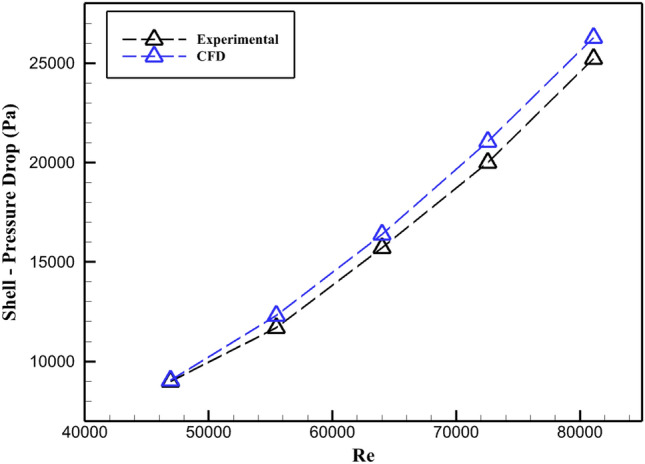
Comparison of the PD results from He and Li’s experiments with the CFD simulation 10.
Fig. 5.
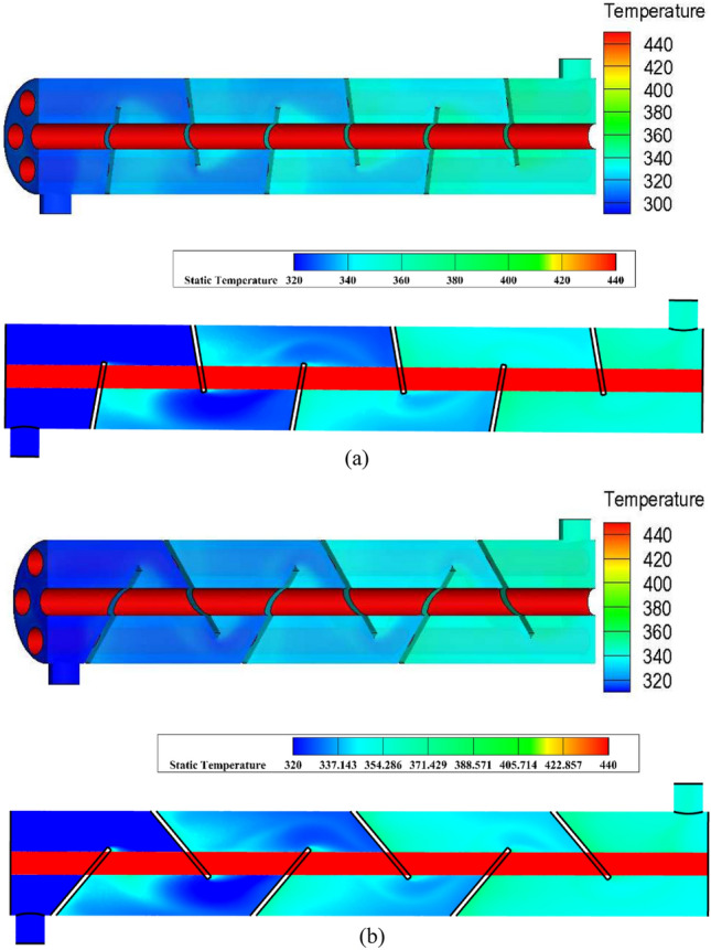
Comparing the temperature distribution cross sectional contours with Youcef and Saim numerical study, (a) 10° inclination angle, (b) 40° inclination angle 22.
Key findings and analysis
This research initially examines how varying baffle inclination angles impact several factors: the OHT, PD, shell side HTC, outlet temperatures of both the hot and cold fluids and the PEC. The primary objective is to identify the optimal baffle configuration. The research then investigates how changing the quantity of baffles affects the aforementioned parameters while preserving the ideal inclination angle. Six more baffles with various inclination degrees have been designed, since the Segmental baffle with a 0° inclination angle is the first baffle examined in the article. The alternate baffles have an inclination of 5°-30°. This diversity in design allows for comparison and simulation, which makes choosing the best baffle easier. In the second part of this analysis, the number of baffles will be changed to determine how the selected ideal angle affects a STHE’s performance. This section’s findings hold true for shell-side Reynolds numbers for 0.5–2.5 kg/s mass flow rates, which are 6400–33,400.
Baffle inclination effects on thermal efficiency
Figure 6 demonstrates that OHT rises for all baffle inclination angles when the flow rate of hot fluid inlet the shell is increased. The highest overall heat transfer values in the shell are observed with baffles inclined at 30°, while baffles positioned at 0° exhibit the lowest overall heat transfer values. Differences between different baffles’ OHT values are not very noticeable at lower flow rates, but at larger flow rates, there is a noticeable discrepancy. Inclined baffles cause disturbance in the thermal boundary layer, hence intensifying the interfacial mixing of the shell-side fluid with tube surfaces. In local regions, the effect is most effective at 30° where turbulence significantly increases OHT by 4.2% in comparison with non-inclined baffles with a mass flow rate of 1.5 kg/s.
Fig. 6.
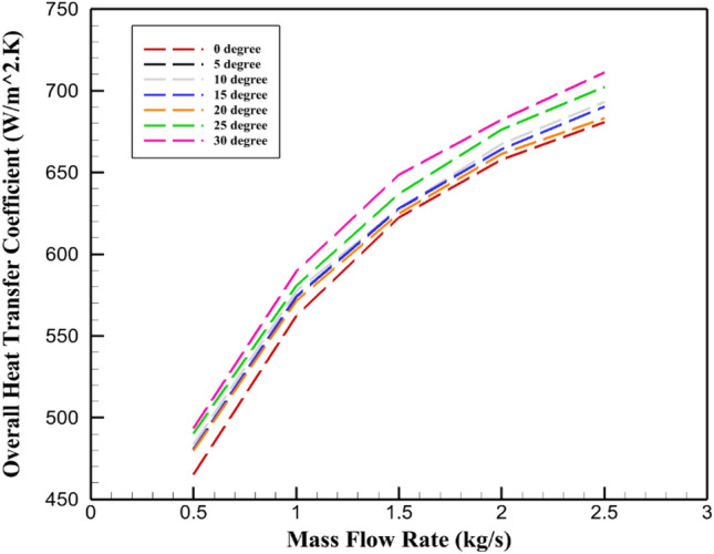
Relationship between OHT and mass flow rate for various baffle inclination angles in a STHE.
Baffle inclination angle effect on shell side HTC
As depicted in Fig. 7 the shell-side HTC increasing by increment in the baffle inclination angle. In comparison to the baffle without inclination angle, the percentage of the raise in shell side HTC with an increase in the inclination angle of the baffles from 5° to 30° in the 1.5 kg/s mass flow rate are 1.42%, 3.97%, 5.13%, 6.044%, 10.8%, 24.85%, respectively. The discrepancy between the HTC values are not significant at low mass flow rates, but it has become more noticeable by rising in the mass flow rates. There is a clear correlation between the shell side HTC and turbulence of the fluid flow through the shell. According to Fig. 7, as the inclination angle of the baffles increased, the fluid’s turbulence also rises, the HTC has consequently increased significantly.
Fig. 7.
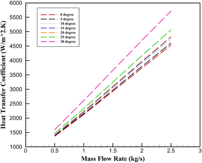
Relationship between shell-side HTC and mass flow rate for various baffle inclination angles in a STHE.
Pressure drop for different inclination angles of baffles
Baffles in heat exchangers with a 30° inclination experience a larger PD as a result of dead zones forming and obstructing fluid flow. Figure 8 demonstrates that as the flow rate inside the shell increases, the PD also rises; 30° inclined baffles exhibit the highest PD, while Baffles positioned at 0° exhibit the least PD, especially when flow rates are high, the distinct fluid flow pattern in 30° inclined baffles significantly boost PD. Inclined baffles disrupt boundary layers-both thermal and those of the velocity-more effectively on the tube surfaces. The thickness of the boundary layer reduces, thereby increasing the convection heat transfer mechanism. The increase in pressure drop on the other hand is because of higher energy dissipation mechanisms due to frequent flow redirection.
Fig. 8.

Relationship between PD and mass flow rate for various baffle inclination angles in a STHE. (shell side).
Baffle inclination angle influence on cold water outlet temperature
Figure 9 depicts the hot fluid mass flow rate versus the cold fluid outlet temperature at several baffle inclination angles for STHE. The primary role of baffles is the intensification of the fluid mixing due to flow disruptions and, thus, increased interaction of the hot fluid in the shell with the cold fluid in the tubes. The influence of increased thermal exchange is considerable, especially at higher values of the inclined angle: such effect produces high increases in the cold fluid’s outlet temperatures at both 25° and 30°. Figure 10a–g shows that the cold fluid outlet of the tubes reaches its highest temperature with baffles inclined at 30° and its lowest temperature with baffles inclined at 0°. It can be inferred that baffles with an angle of 30° have the largest OHTs, whilst baffles with an angle of 0° have the lowest. Temperature changes are now evident in the ends of tubes. Figure 11a–g displays the temperature distribution within the STHE. As shown, the cold water at the tube’s outlet sections has a higher temperature as a result of increasing the inclination angle of the baffles. The cold water’s temperature rises in proportion to the number of higher temperature tubes at the outlet sections. When compared to the 0° inclined baffles, the 25° and 30° inclined baffles exhibit the largest temperature variations at the outlet sections of the tubes.
Fig. 9.
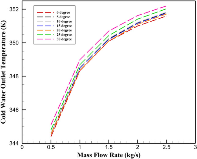
Relationship between cold water outlet temperature and mass flow rate for various baffle inclination angles in a STHE. (shell side).
Fig. 10.

Tube side temperature distribution for various inclination angle of the baffles. (a) 0°, (b) 5°, (c) 10°, (d) 15°, (e) 20°, (f) 25°, (g) 30.
Fig. 11.

Cross-sectional views of temperature distribution contours at the first plane of STHE for various inclination angle of baffles. (a) 0°, (b) 5°, (c) 10°, (d) 15°, (e) 20°, (f) 25°, (g) 30°
PEC across varied baffle inclination angles
In this simulation, the PEC is used to calculate the final evaluation and the best inclination angle for baffles. This metric is based on the HTC and PD, two crucial characteristics of STHEs, these findings are examined in more depth in the section on validating results. For each baffle inclination angle under investigation, the PEC has been calculated dependently. This ratio is defined as the amount of HTC divided by the PD and the basis of the comparison is 0° inclined angle. Better overall performance is indicated by a higher PEC value; hence, baffles with higher heat transfer and lower PD are thought to be more effective than their counterparts. The investigation’s best baffling layout has been established and successfully visualized through a comparison analysis of the data collected, thus showing how different angles may be the best solutions to improve heat exchanger efficiency. This method illustrates the vital importance of taking into account the flow resistance and the heat transfer capacities when it comes to choosing the best baffle design to achieve maximum efficiency in STHE applications. The end of the selection process serves not only to unravel the complex interactions between baffle geometry, fluid dynamics, and heat transfer performance but also to positively influence design decisions for next heat exchangers. The baffles with 25° and 5° inclination angles had the highest and lowest PEC values, respectively, as shown in Fig. 12. The 30° inclined baffle has a far larger PD value than the other baffles. For baffles that are inclined 5° to 30°, the numerical values of PEC are 1.024, 1.05, 1.072, 1.08, 1.106, 1.08 at 1.5 kg/s in comparison with 0° inclined baffles.
Fig. 12.
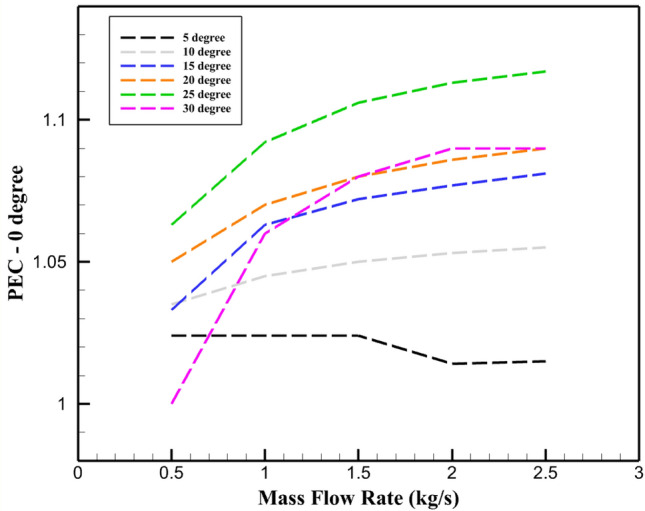
PEC (with the basis of 0° inclined baffles) across inclination angle of baffles for different mass flow rates. (Shell-Side).
Applying different quantities of 25° angled baffles
An analysis of several baffles was carried out in the part before this one, which included a comparison of the contributing factors. In the end, the performance was used to determine which baffle inclination angle was the most effective. After using the simulation method to examine several baffle inclination angles in this investigation, the 25° inclined baffle was found to be the best. The study examines several key parameters, including OHT, outlet temperatures of both hot and cold fluids, and PEC. In summary, the ideal quantity of 25° inclined baffles are determined by a thorough analysis and comparison of the given data. There are 4 to 10 baffle amounts in the study. Figure 13a–d displays STHE layouts with varying baffle counts, all set at a 25° angle.
Fig. 13.

STHE with various numbers of segmental baffles with 25° inclination angle, (a) 4, (b) 6, (c) 8, (d) 10.
Impact of 25° inclined baffle count on OHT
Figure 14 illustrates rising shell-side OHT as baffle count increases. The enhanced number of baffles boosts the OHT by intensifying the turbulent flow of fluid within the shell. In particular, the OHT values for setups with 4, 6, 8, and 10 baffles are recorded as 588.7, 636.83, 667.73, 690.95 W/m2 K, respectively, at 1.5 kg/s. The data indicates a significant 17.4% enhancement in heat transfer efficiency when baffle quantity is raised from 4 to 10. This correlation between OHT and baffle count can be attributed to the heightened turbulence and improved fluid mixing resulting from the additional baffles. The additional baffles are an excellent way to increase the interaction of the hot and cold fluids in the heat exchanger which in turn will lead to maximizing the surface area for the heat transfer. The boosted turbulence destroys the thermal boundary layer, making it possible to transfer heat more effectively. Hence, baffle quantity optimization in a STHE’s configuration is the key to attaining the highest thermal performance. The results imply that increasing the baffle number has a lot of positive impacts on the heat transfer which is one of the main factors to be evaluated while designing and operating these systems.
Fig. 14.
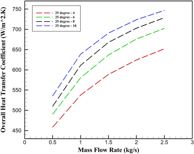
Correlation between OHT and mass flow rate in STHE with varying quantities of 25° inclined baffle. (shell-side).
Impact of 25° inclined baffle count on shell-side HTC
According to the Fig. 15, the shell-side HTC has likewise been increased as the number of the 25° inclined baffles has grown. This phenomena is caused by decreasing the baffle spacing and the ongoing, sequential changes in the shell-side flow, which have raised the amount of flow’s turbulence. At 1.5 kg/s mass flow rate, the shell-side HTC for four, six, eight and ten 25° inclined baffles are 2588.2, 3246, 3705 and 4144 W/m2 K, respectively. The shell side HTC has grown in all simulated STHE in tandem with the mass flow rate increased. The HTC of the STHE with four, six, eight and ten 25° inclined baffles has seen a 206.71%, 245.77%, 272.16% and 289.23% rise for mass flow rate from 0.5 to 2.5 kg/s.
Fig. 15.

Correlation between shell side HTC and mass flow rate in STHE with varying quantities of 25° inclined baffle. (shell-side).
PD across varying quantities of 25° angled baffles
Figure 16 demonstrates that the PD rises in proportion to the increase in baffle quantity. The addition of more baffles, which reduces the gap between them, is associated with more frequent and sudden alterations in the fluid’s trajectory within the shell. Consequently, this enhancement contributes to an elevated PD within the shell. Simultaneously, a higher shell fluid flow rate is noted, along with a more noticeable increase in PD. At a 1.5 kg/s flow rate, the PD values for baffles 4, 6, 8, and 10 are 5544, 7078, 9305.5, and 13,240 Pa, in that order. as 10 baffles are used at 1.5 kg/s, the PD is increased significantly, increasing by 138.8% as compared to 4 baffles.
Fig. 16.

Relationship between PD and mass flow rate in a STHE with varying 25° inclined baffle configurations. (shell-side).
Thermal characteristics of cold water discharge at 25° baffle inclination angle
Figure 17 demonstrates that the outlet temperature of the cold water in the tubes increases correlatively with both the quantity of baffles and the incoming flow rate of the heated water in STHE. This phenomenon is caused by the heightened OHT. A higher baffle count forces the fluid to change course more often, promoting better thermal exchange between the hot water and a greater tube surface. This process consequently elevates the temperature of the cold fluid flowing through the tubes. When the flow rate reaches 1.5 kg/s, the outlet temperature of the cold fluid for 4, 6, 8, and 10 baffles reaches 349.11, 350.43, 351.17, and 351.67 K, respectively. An analysis comparing the lowest and highest fluid temperatures reveals that the outlet temperature of the cold stream has risen by 0.73%. This increase is attributed to the combined effects of adding more baffles and elevating the mass flow rate of the heated fluid in the shell region. Figure 18a–d illustrate the thermal profiles of both the heated and cold fluids, as well as their respective flow patterns within the STHE. The cold fluid’s temperature inside the tubes has improved as a result of increasing the number of baffles, which caused the cold fluid to exhibit temperature variations earlier and before reaching the bent section, as indicated by the contours were obtained. The cold fluid exits the tubes at a higher temperature at the outlet section, which is another effect of this phenomenon. According to the Fig. 19(a-d), due to their greater length and more contact with the hot fluid, the four tubes which positioned horizontally at the top of the tube arrangement have demonstrated a higher temperature at the outlet section.
Fig. 17.

Relationship between mass flow rate and cold fluid outlet temperature in the STHE. (shell-side).
Fig. 18.

Thermal profiles along fluid pathways in the tube region, depicted for multiple 25° inclined baffle arrangements, (a) 4, (b) 6, (c) 8, (d) 10.
Fig. 19.

Cross-sectional views of temperature distribution contours at the first plane of STHE for various numbers of 25° inclined baffles. (a) 4, (b) 6, (c) 8, (d) 10.
Impact of increasing baffle count on fluid flow patterns
The results show velocity patterns of fluid flow in a STHE with 25° angled baffles, ranging from four to ten baffles. As the number of baffles increases, significant flow patterns and velocity distribution changes have been observed. With fewer baffles, large areas of high-velocity flow exist between baffles, with some turbulence near them. As more baffles are added, the high-velocity regions become smaller and more frequent, while turbulent areas expand. The flow patterns gradually shift from slightly diagonal to more complex and intricate. With ten baffles, the flow becomes highly turbulent, with small, frequent high-velocity regions and the emergence of some low-velocity areas. Figure 20a–d shows increasing the number of baffles leads to more complex and turbulent flow patterns throughout the exchanger. These changes in flow patterns as the number of baffles increases have several effects on the heat exchanger’s performance. More baffles create a more even distribution of flow across the shell side, likely improving heat transfer by ensuring more fluid contacts the tubes. The increased frequency of velocity changes and higher turbulence enhance mixing, which can boost heat transfer efficiency. However, more baffles also increase the overall PD in the system, potentially requiring more pumping power. The increase in baffles also extends the effective flow path length, providing more opportunity for heat transfer but increasing fluid residence time. This complex interplay of factors means that the optimal number of baffles would depend on specific design requirements, balancing improved heat transfer performance against increased PD and pumping power needs.
Fig. 20.
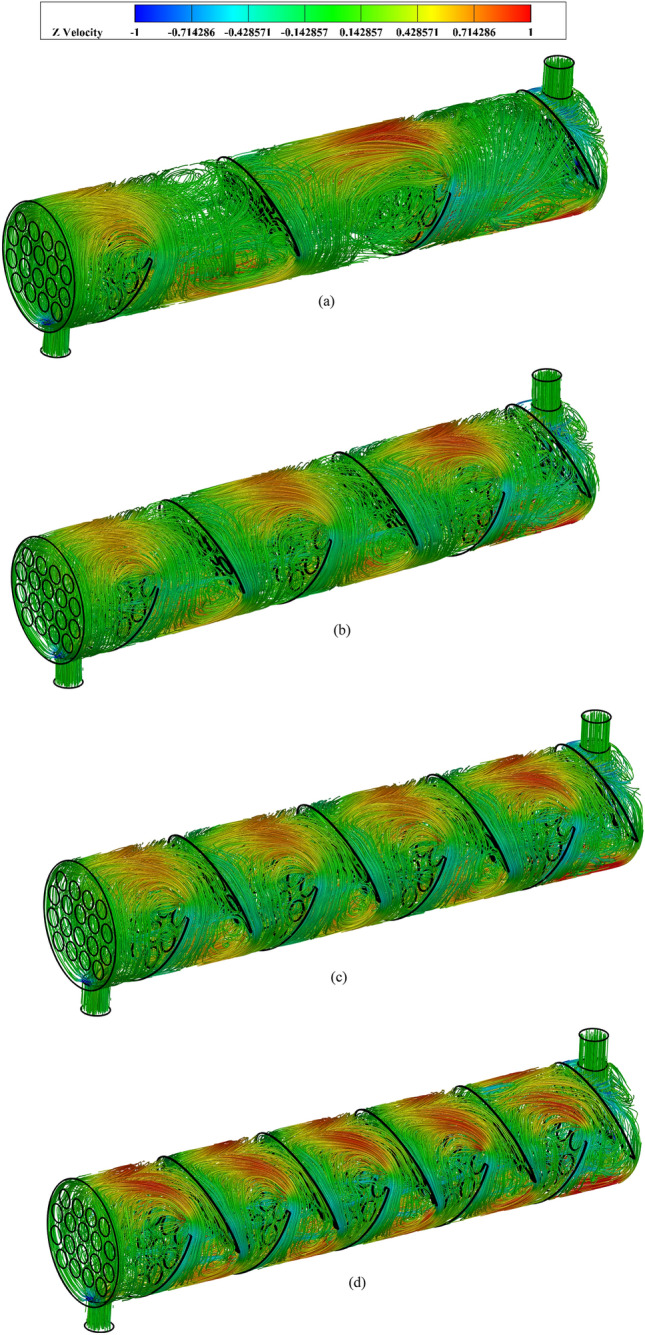
Velocity patterns of fluid flow, illustrated through streamlines, for varying numbers of 25° angled baffles: (a) 4, (b) 6, (c) 8, (d) 10. (shell side).
PEC for different numbers of 25° inclined baffles
Since PEC comprises the two most crucial STHE parameters—HTC and PD—it is the primary and most significant component in assessing STHE performance and selecting the optimal STHE. The PEC value increases with increased HTC and decreasing PD. Figure 21 shows that in a STHE with a flow rate of 1.5 kg/s, the PEC changes based on the number of baffles. The PEC values are 1.157, 1.206 and 1.203 for 6, 8, and 10 baffles respectively. The collected data suggests that among the various baffle configurations examined, the STHE equipped with eight baffles demonstrates superior performance compared to designs with different numbers of baffles. As depicted in Fig. 21, a remarkable finding emerges: STHE configured with 8 baffles exhibits peak performance at a flow rate of 2.5 kg/s. At this point in the simulation, it achieves an exceptionally high value of 1.24, which stands out as the maximum observed across all configurations tested.
Fig. 21.

The PEC values for various quantities of baffles inclined at 25°, plotted against the mass flow rate. (shell-side).
Conclusion
This study employed numerical modeling techniques to investigate how different baffle inclination angles, and the number of baffles affect the performance of STHEs. Research has also been done on the number of baffles—4, 6, 8, and 10—after the optimal inclination angle has been determined. The baffles’ inclination angles ranged from 0° to 30°.
When compared to other baffle forms, 30° inclined baffles showed improved thermal performance, resulting in a 4.2% improvement in OHT at 1.5 kg/s.
According to the simulations outcomes, by increasing the inclination angle of the baffles from 5° to 30°, at 1.5 kg/s mass flow rate, the shell side HTC raised by 1.42%, 3.97%, 5.13%, 6.044%, 10.8%, 24.85%, respectively.
At 1.5 kg/s, baffles with 0° to 20° inclinations show reductions in PD of 0.14%, 1.97%, 4.4%, and 5.25% compared to non-inclined baffles.
The data indicates that when operating at 1.5 kg/s, the temperature increase of cold water varies with baffle inclination angles from 0° to 30°. The observed temperature rises are 57.1, 57.24, 57.27, 57.19, 57.1, 57.43, and 57.7 K, corresponding to the increasing inclination angles.
Baffles with an inclination angle of 25° function better than others. For baffles that are inclined from 5° to 30°, the PEC values are 1.024, 1.05, 1.072, 1.08, 1.106, 1.08 at 1.5 kg/s, respectively in comparison with the 0° inclined baffles.
As the number of baffles increases, OHT Coefficients also rise. At 1.5 kg/s, the OHT values progress from 588.7 W/m2.K with 4 baffles, to 636.83 W/m2.K with 6 baffles, then 667.73 W/m2.K with 8 baffles, and finally 690.95 W/m2.K with 10 baffles. This data shows that increasing the number of baffles from 4 to 10 results in a 17.4% improvement in the OHT.
The shell-side HTC has been increased by raising in the number of 25° inclined baffles. At the 1.5 kg/s mass flow rate the HTC for the four, six, eight and ten 25° inclined baffles are 2588.2, 3246, 3705 and 4144 W/m2.K, respectively. It was observed that the HTC was maximum at the 2.5 kg/s mass flow rate and rose by 28.8% when the number of baffles was raised from 6 to 10.
PD increases as the number of baffles grows. At a flow rate of 1.5 kg/s, the PD measurements are 5544 Pa for 4 baffles, 7078 Pa for 6 baffles, 9305.5 Pa for 8 baffles, and 13,240 Pa for 10 baffles. Notably, the 10 baffle configuration at this flow rate exhibits a significant 138.8% increase in PD compared to the 4-baffle setup, demonstrating a substantial intensification.
For a STHE with 6, 8, 10 baffles at 1.5 kg/s, the PEC values are 1.157, 1.206 and 1.203, correspondingly in comparison with four 25° inclined baffle.
Abbreviations
- Pr
Prandtl number
- ṁ
Mass flow rate [kg/s]
- ε
Turbulent dissipation rate
- HTC
Heat transfer coefficient
- in
Inlet
- PEC
Performance evaluation criteria
- T
Temperature [K]
- Ds
Shell outer diameter [mm]
- μ
Dynamic viscosity [kg/m s]
- STHE
Shell and tube heat exchanger
- eff
Effective
- Do
Tubes outer diameter [mm]
- Q
Heat transfer rate [W]
- PD
Pressure Drop
- c
Cold
- k
Turbulent kinetic energy
- Nt
Number of tubes
- ρ
Density [kg/m3]
- out
Outlet
- cp
Specific heat capacity [J/(kg K)]
- HE
Heat exchanger
- As
Shell cross flow area [m2]
- h
Hot
- Δ
Difference
- o
Outer
- P
Pressure [pa]
- OHT
Overall heat transfer coefficient
- t
Total
Author contributions
M.M.: Software, Validation, Investigation B.J.: Supervision K.H.: Methodology, Software M.P.: Formal analysis, Writing—Original Draft, Writing—Review & Editing.
Data availability
The datasets used and/or analysed during the current study are available from the corresponding author on reasonable request.
Competing interests
The authors declare no competing interests.
Footnotes
Publisher’s note
Springer Nature remains neutral with regard to jurisdictional claims in published maps and institutional affiliations.
References
- 1.El-Said, E. M. S. & Al-Sood, M. M. A. Shell and tube heat exchanger with new segmental baffles configurations: A comparative experimental investigation. Appl. Therm. Eng.150, 803–810 (2019). [Google Scholar]
- 2.Mimi Elsaid, A. et al. Performance characteristics of shell and helically coiled tube heat exchanger under different tube cross-sections, inclination angles and nanofluids. Case Stud. Therm. Eng.49, 103239 (2023). [Google Scholar]
- 3.Tang, L. et al. Investigation of a falling film tube bank heat exchanger with baffle design for water recovery applications. Energy Built Environ.5(5), 817–828 (2024). [Google Scholar]
- 4.Vasconcelos-Segundo, E. H. D. et al. Economic optimization design for shell-and-tube heat exchangers by a Tsallis differential evolution. Appl. Therm. Eng.111, 143–151 (2017). [Google Scholar]
- 5.Ghanei, A. et al. Thermal-economic multi-objective optimization of shell and tube heat exchanger using particle swarm optimization (PSO). Heat Mass Transf.50(10), 1375–1384 (2014). [Google Scholar]
- 6.Kakaç, S., Liu, H. & Pramuanjaroenkij, A. Heat Exchangers: Selection, Rating, and Thermal Design 3rd edn. (Taylor & Francis, 2012). [Google Scholar]
- 7.Nagaeswara Rao, B. & Pavanu Sai, J. Numerical investigation of thermo-hydraulic ability of STHX with continuous helical baffles on the shell side. In Materials Today: Proceedings, (2023).
- 8.Akif-kartal, M. & Feyzioğlu, A. Numerical analysis of multipurpose shell-tube-heat exchanger withal stylized geometry at different baffle gaps and various flow rates. Case Stud. Therm. Eng.52, 103810 (2023). [Google Scholar]
- 9.Kunwer, R., Pandey, S. & Bhurat, S. S. Comparison of selected shell and tube heat exchangers with segmental and helical baffles. Therm. Sci. Eng. Prog.20, 100712 (2020). [Google Scholar]
- 10.He, L. & Li, P. Numerical investigation on double tube-pass shell-and-tube heat exchangers with different baffle configurations. Appl. Therm. Eng.143, 561–569 (2018). [Google Scholar]
- 11.Aridi, R. et al. CFD analysis on the spatial effect of vortex generators in concentric tube heat exchangers–a comparative study. Int. J. Thermofluids16, 100247 (2022). [Google Scholar]
- 12.Kallannavar, S., Mashyal, S. & Rajangale, M. Effect of tube layout on the performance of shell and tube heat exchangers. Mater. Today Proc.27, 263–267 (2020). [Google Scholar]
- 13.Fetuga, I. A. et al. Numerical analysis of thermal performance of waste heat recovery shell and tube heat exchangers on counter-flow with different tube configurations. Alex. Eng. J.64, 859–875 (2023). [Google Scholar]
- 14.Petinrin, M. & Dare, A. Performance of shell and tube heat exchangers with varying tube layouts. Br. J. Appl. Sci. Technol.12, 1–8 (2016). [Google Scholar]
- 15.Milcheva, I., Heberle, F. & Brüggemann, D. Modeling and simulation of a shell-and-tube heat exchanger for organic rankine cycle systems with double-segmental baffles by adapting the Bell-Delaware method. Appl. Therm. Eng.126, 507–517 (2017). [Google Scholar]
- 16.Mohammadzadeh, A. M., Jafari, B. & Hosseinzadeh, K. Comprehensive numerical investigation of the effect of various baffle design and baffle spacing on a shell and tube heat exchanger. Appl. Therm. Eng.249, 123305 (2024). [Google Scholar]
- 17.Naqvi, S. M. A. et al. Numerical analysis on performances of shell side in segmental baffles, helical baffles and novel clamping anti-vibration baffles with square twisted tubes shell and tube heat exchangers. Energy Proc.158, 5770–5775 (2019). [Google Scholar]
- 18.Zhou, G.-Y. et al. A numerical study on the shell-side turbulent heat transfer enhancement of shell-and-tube heat exchanger with trefoil-hole baffles. Energy Proc.75, 3174–3179 (2015). [Google Scholar]
- 19.Nasyrlayev, N. et al. A perforated baffle design to improve mixing in contact tanks. Water12(4), 1022 (2020). [Google Scholar]
- 20.Liu, J. J., Liu, Z. C. & Liu, W. 3D numerical study on shell side heat transfer and flow characteristics of rod-baffle heat exchangers with spirally corrugated tubes. Int. J. Therm. Sci.89, 34–42 (2015). [Google Scholar]
- 21.Karuppa, T. & Ganne, S. Shell side numerical analysis of a shell and tube heat exchanger considering the effects of baffle inclination angle on fluid flow using CFD. Therm. Sci.16, 1165–1174 (2012). [Google Scholar]
- 22.Youcef, A. & Saim, R. Numerical analysis of the baffles inclination on fluid behavior in a shell and tube heat exchanger. J. Appl. Comput. Mechanics7(1), 312–320 (2021). [Google Scholar]
- 23.Uosofvand, H., Abbasian Arani, A. A. & Arefmanesh, A. Effect of baffle orientation on shell tube heat exchanger performance. J. Heat Mass Transf. Res.4(2), 83–90 (2017). [Google Scholar]
- 24.Mellal, M. et al. Hydro-thermal shell-side performance evaluation of a shell and tube heat exchanger under different baffle arrangement and orientation. Int. J. Therm. Sci.121, 138–149 (2017). [Google Scholar]
- 25.Wang, X. et al. Numerical analysis and optimization study on shell-side performances of a shell and tube heat exchanger with staggered baffles. Int. J. Heat Mass Transf.124, 247–259 (2018). [Google Scholar]
- 26.Gugulothu, R., et al. Numerical Study on Shell and Tube Heat Exchanger with Segmental Baffle. in Proceedings of International Joint Conference on Advances in Computational Intelligence. (Singapore: Springer Singapore, 2021).
- 27.Abdelkader, B. A. & Zubair, S. M. The effect of a number of baffles on the performance of shell-and-tube heat exchangers. Heat Transf. Eng.40(1–2), 39–52 (2019). [Google Scholar]
- 28.Al-darraji, A. R. et al. Enhancement of heat transfer in a vertical shell and tube heat exchanger using air injection and new baffles: Experimental and numerical approach. Appl. Therm. Eng.236, 121493 (2024). [Google Scholar]
- 29.Wang, J., Wang, J. & Feng, L.-F. Numerical study on hydrodynamics, mixing and heat transfer of highly viscous fluid in a novel shell-and-tube heat exchanger with X-type baffles. Chem. Eng. Res. Des.205, 556–568 (2024). [Google Scholar]
- 30.Saini, P., Dhar, A. & Powar, S. Performance enhancement of fin and tube heat exchanger employing curved trapezoidal winglet vortex generator with circular punched holes. Int. J. Heat Mass Transf.209, 124142 (2023). [Google Scholar]
- 31.Brodnianská, Z. & Kotšmíd, S. Heat transfer enhancement in the novel wavy shaped heat exchanger channel with cylindrical vortex generators. Appl. Therm. Eng.220, 119720 (2023). [Google Scholar]
- 32.Zhao, L. et al. Analysis of the thermal improvement of plate fin-tube heat exchanger with straight and curved rectangular winglet vortex generators. Case Stud. Therm. Eng.51, 103612 (2023). [Google Scholar]
- 33.Gururatana, S. et al. Development of heat transfer performance in tubular heat exchanger with improved NACA0024 vortex generator. Case Stud. Therm. Eng.26, 101166 (2021). [Google Scholar]
- 34.Bai, Z. et al. Bow-shaped vortex generators in finned-tube heat exchangers; ANN/GA-based hydrothermal/structural optimization. Case Stud. Therm. Eng.55, 104135 (2024). [Google Scholar]
- 35.Dong, C. et al. An analysis of performance on trisection helical baffles heat exchangers with diverse inclination angles and baffle structures. Chem. Eng. Res. Des.121, 421–430 (2017). [Google Scholar]
- 36.Zhang, J.-F. et al. Experimental performance comparison of shell-side heat transfer for shell-and-tube heat exchangers with middle-overlapped helical baffles and segmental baffles. Chem. Eng. Sci.64(8), 1643–1653 (2009). [Google Scholar]
- 37.Jalili, P. et al. Investigation of thermal analysis and pressure drop in non-continuous helical baffle with different helix angles and hybrid nano-particles. Case Stud. Therm. Eng.36, 102209 (2022). [Google Scholar]
- 38.Shinde, S. & Chavan, U. Numerical and experimental analysis on shell side thermo-hydraulic performance of shell and tube heat exchanger with continuous helical FRP baffles. Therm. Sci. Eng. Prog.5, 158–171 (2018). [Google Scholar]
- 39.Lei, Y.-G. et al. Effects of baffle inclination angle on flow and heat transfer of a heat exchanger with helical baffles. Chem. Eng. Process.47(12), 2336–2345 (2008). [Google Scholar]
- 40.Gao, B. et al. Experimental study of effects of baffle helix angle on shell-side performance of shell-and-tube heat exchangers with discontinuous helical baffles. Exp. Therm. Fluid Sci.68, 48–57 (2015). [Google Scholar]
- 41.Andrews, M. J. & Master, B. I. Three-dimensional modeling of a helixchanger® heat exchanger using CFD. Heat Transf. Eng.26(6), 22–31 (2005). [Google Scholar]
- 42.Maghrabie, H. M., Attalla, M. & Mohsen, A. A. A. Performance of a shell and helically coiled tube heat exchanger with variable inclination angle: Experimental study and sensitivity analysis. Int. J. Therm. Sci.164, 106869 (2021). [Google Scholar]
- 43.Gu, H. et al. Numerical study on performances of small incline angle helical baffle electric heaters with axial separation. Appl. Therm. Eng.126, 963–975 (2017). [Google Scholar]
- 44.Wen, J. et al. Numerical investigation on the multi-objective optimization of a shell-and-tube heat exchanger with helical baffles. Int. Commun. Heat Mass Transf.89, 91–97 (2017). [Google Scholar]
- 45.Daneshparvar, M. R. & Beigzadeh, R. Multi-objective optimization of helical baffles in the shell-and-tube heat exchanger by computational fluid dynamics and genetic algorithm. Energy Rep.8, 11064–11077 (2022). [Google Scholar]
- 46.Kumaresan, G. et al. Numerical analysis of baffle cut on shell side heat exchanger performance with inclined baffles. Heat Transfer Eng.39(13–14), 1156–1165 (2018). [Google Scholar]
Associated Data
This section collects any data citations, data availability statements, or supplementary materials included in this article.
Data Availability Statement
The datasets used and/or analysed during the current study are available from the corresponding author on reasonable request.