

Abstract
Micro/nanomotors (MNMs) are highly versatile small‐scale devices capable of converting external energy inputs into active motion. Among the various energy sources, light stands out due to its abundance and ability to provide spatiotemporal control. However, the effectiveness of light‐driven motion in complex environments, such as biological tissues or turbid water, is often limited by light scattering and reduced penetration. To overcome these challenges, recent innovations have integrated light‐based actuation with other external stimuli—such as magnetic, acoustic, and electrical fields—broadening the functional range and control of MNMs. This review highlights the cutting‐edge developments in dual‐energy powered MNMs, emphasizing examples where light is paired with secondary energy sources for enhanced propulsion and task performance. Furthermore, insights are offered into the fabrication techniques, biomedical applications, and the future directions of such hybrid MNMs, while addressing the remaining challenges in this rapidly evolving field.
Keywords: biomedical applications, dual‐energy sources, multifunctional systems, photocatalytic micro/nanomotors
Photoresponsive micro/nanomotors combined with external stimuli such as magnetic, acoustic, and electrical fields enhance functionality and control in self‐propelled systems. This review presents an overview of hybrid micro/nanomotors, covering material design, fabrication methods, and biomedical applications. Challenges and future directions are highlighted to inspire further advancements in this rapidly evolving field.

1. Introduction
Light, as an abundant and renewable energy source, is fundamental to life on Earth, powering essential biological processes and presenting an ideal energy supply for various technological applications. Scientists are not only fascinated to explore different light‐assisted reactions, such as photocatalytic H2 production, CO2 reduction, and NH3 synthesis but also eager to develop appropriate photoactive materials that enable better solar light harvesting. Particularly, the study of light‐driven micro/nanomotors (LMNMs), also termed micro/nanorobots, micro/nanomachines, and micro/nanoswimmers, has emerged as a hot research field in recent decades, which refers to the micro/nanoscale objects with the ability of autonomous motion in solution upon light illumination. Similar to other externally powered MNMs that utilize magnetic, electric, and acoustic fields, LMNMs convert external energy into mechanical motion, enabling a diverse range of advanced applications, including environmental remediation, drug delivery, and therapeutical treatments.
Micro/nanoscale machines must overcome the challenges of low Reynolds number hydrodynamics (R << 1), which causes kinematic reversibility, as well as the random walking trajectory induced by Brownian force.[ 1 ] Significant progress in understanding the functioning of LMNMs has led to the development of sophisticated strategies to optimize their propulsion and precise manipulation. From an actuation perspective, the motion mechanisms of LMNMs can be classified into three categories: photo‐induced chemical reactions, photo‐induced thermal propulsion, and photo‐induced deformation. As many other excellent reviews have comprehensively covered the motion behaviors of LMNMs induced by different propulsion mechanisms,[ 2 , 3 , 4 ] in this review, we will primarily address the autonomous motion based on the photochemical reactions, in which the propulsive force is generated by an asymmetric gradient produced through a photocatalytic reaction. In addition, the photothermal effect of LMNMs is included in the discussion of biomedical applications, where light‐to‐heat is utilized to trigger therapeutic treatments.
Two main strategies have been employed to achieve the efficient self‐propulsion of LMNMs in terms of photocatalytic performance and constructing anisotropic structures. On the one hand, extensive efforts are being devoted to enhancing the separation efficiency of the photogenerated carriers of LMNMs through various approaches, such as bandgap engineering,[ 5 ] heterojunction formation,[ 6 ] surface functionalization,[ 7 ] and noble metal cooperation.[ 8 ] On the other hand, the design of asymmetric or anisotropic morphologies generates unbalanced gradient distributions around LMNMs, which in turn propels them to move forward efficiently.[ 9 , 10 ]
Besides material properties, precise motion control is critical for the practical applications of LMNMs. Typically, adjusting parameters such as light intensity, polarization, frequency, and propagation direction enables the controllability of the speed and motion direction of LMNMs. Compared to other stimuli, optically driven systems offer unrivaled merits, such as easy installation of the experimental setup and adjustability of multiple parameters. However, common limitations associated with this external energy source still persist. For instance, adjusting light intensity only alters the speed of LMNMs, without providing precise navigation unless more complex devices are used to modulate light polarization. Additionally, UV and visible light sources exhibit limited tissue penetration, restricting its biomedical uses. Alternative strategies for controlling the motion performance of LMNMs, including the optothermal manipulation,[ 11 , 12 ] opto‐hydrodynamic driven,[ 13 , 14 , 15 ] optical force‐driven,[ 16 , 17 , 18 ] and biohybrid phototaxis,[ 19 , 20 , 21 ] may also encounter the unavoidable challenges in biomedical applications, such as the limited light penetration depth, light scattering, light manipulation in vivo and immunoreactions. In this regard, optical actuation coupled with other types of stimuli, e.g., chemical fuel, magnetic, electric, and acoustic fields, offers potential advantages to achieve greater versatility and programmability.
Integrating the optical actuation of MNMs with other propulsion modes is not merely about combining different energy sources. Instead, it offers unique opportunities for synergistic effects, drawing on the specific advantages of each propulsion mechanism. For instance, chemical‐fuelled MNMs move under the impetus of chemical gradients generated by reactions occurring on their surfaces, which can be readily achieved.[ 22 ] Magnetic responsive MNMs are capable of being guided through external magnetic fields, providing a penetrating and safe way to access the biological environment.[ 23 ] Electric field‐powered MNMs are endowed with considerable potential for realizing more complex three‐dimensional (3D) motion.[ 24 , 25 ] Acoustic propulsion exhibits excellent tolerance to high ionic strength and viscous fluids, which is compelling for biomedical applications.[ 26 ] Therefore, depending on the selected combination, different motion behaviors can be predictably programmed.
Pioneering research has realized the combination of different energy sources into a single motor, including chemical/acoustic,[ 27 , 28 ] chemical/magnetic,[ 29 ] optical/chemical, and others,[ 30 , 31 ] which combine the advantages of each type of stimulus into a single system. For example, by applying a magnetic field to an LMNM, the direction of the LMNM can be oriented toward the direction of the magnetic field.[ 32 ] In addition, the magnetic field has the ability to enhance charge separation in photocatalytic nanomotors, thereby improving its motion speed and photoactivity.[ 33 ] With the cooperation of optical and chemical fuels, MNMs may exhibit various behaviors, such as acceleration, break, and even reverse motion, depending on whether these two propulsive forces are always in the same direction.[ 34 ] The application of electric fields to optical‐powered MNMs enables easy control over their rotational behaviors. For optical/acoustic‐powered MNMs, the collective behavior of MNMs can be triggered and manipulated by selectively irradiating the light pattern at different spots.[ 35 ]
In this review, we provide a comprehensive and current overview of LMNMs integrated with dual or multiple energy sources, a topic that remains underrepresented in the literature. Existing reviews predominantly focus on general aspects such as design and synthesis,[ 36 , 37 , 38 ] motion manipulation,[ 39 , 40 ] swarm dynamics,[ 41 , 42 , 43 ] or biomedical applications of general MNMs.[ 44 , 45 , 46 ] However, very few explore the specific advances in dual‐energy‐powered LMNMs. Those that do either offer broad discussions across all types of MNMs,[ 47 , 48 ] concentrate only on optical/magnetic combinations,[ 49 ] or lack detailed guidance on material design for future innovations.[ 50 ] Thus, there is a strong need for a holistic overview of light‐assisted dual‐energy‐powered systems, providing insight into their design and applications. Figure 1 provides an overview of the different types of dual‐responsive LMNMs discussed in this review and their corresponding advantages. First, we provide a comprehensive description of cutting‐edge fabrication methods, offering guidance for researchers to expand the possibilities in this field. This is followed by a detailed discussion of the recent developments in various combinations of dual‐energy‐powered LMNMs. Next, we highlight the most representative biomedical applications of these systems. Finally, we offer insights into overcoming current challenges and propose future perspectives on the design and practical applications of dual‐energy‐powered LMNMs.
Figure 1.

Schematic illustration showing the most representative examples of dual‐responsive LMNMs and the corresponding advantages they offer, including enhanced propulsion efficiency, improved control, adaptability in complex environments, and increased functionality in biomedical or environmental applications.
2. Fabrication Methods
The synthesis processes of MNMs are essential for defining their final shape and size, which significantly influence their kinematic behavior, and for equipping these MNMs with dual or multi‐engines capable of responding to multiple stimuli simultaneously. The dual/multi‐energy source‐powered LMNMs might either consist of a single component or multiple components, which can be obtained through a one‐ or multi‐step synthesis, respectively.[ 5 , 51 ] Accordingly, the fabrication strategies that we provide here cover the preparation of both single‐ and dual/multi‐energy‐powered LMNMs. Semiconductor‐based materials are typically used as photo‐responsive counterparts, combined with metals or other semiconductors to obtain heterojunction structures. Therefore, the bandgap of semiconductors is an essential property in the selection of materials, as it determines the wavelength range required to induce the photochemical reaction. Usually, metal/semiconductor MNMs respond to specific wavelengths,[ 52 ] while the design of semiconductor/semiconductor heterostructured MNMs enables exquisite motion manipulation under multiple wavelengths.[ 53 , 54 ] Besides, the decoration of photoactive MNMs with magnetic or electrical particles facilitates their motion actuation under combined external fields, such as optical/magnetic or optical/electrical inputs.[ 55 ]
Once the appropriate components have been selected, the next crucial consideration is the shape control of LMNMs, which plays a key role in breaking the symmetry of the system, leading to an uneven distribution of generated species through mechanisms such as diffusiophoresis or electrophoresis. To date, the most common shapes include Janus spheres, micro/nanorods, star‐shape, micro/nanotubes, nanotrees, and others. It is worth mentioning that the methodology for constructing asymmetric structures on dual‐energy source‐powered LMNMs is the same as that for single‐engine LMNMs, except that the selection of the combined materials requires more careful consideration of their properties. The most common fabrication techniques include hydrothermal synthesis, sol–gel, vapor deposition techniques, and electrodeposition processes, among others. Depending on the desired properties, e.g., size, shape, and propulsion mechanism, different methods are chosen to achieve specific characteristics in an LMNM, either based on one‐step synthesis or involving multistep fabrication techniques.
In this section, we will briefly describe the common techniques used for the synthesis of a dual‐energy‐powered LMNM intending to provide guidance to readers in selecting a viable method to achieve the ideal hybrid LMNMs. As presented in previous sections, the design of optical/chemical and optical/magnetic‐powered MNMs are mainly based on photocatalytic materials with the addition of materials responsive to the second energy source. Therefore, the synthesis of photo‐responsive support plays an important role in the whole fabrication procedure. Hydrothermal (or solvothermal) is the most used method to synthesize semiconductor supports of various shapes and sizes. Subsequently, the combination with other techniques provides a wider scope for obtaining MNMs with different functionalities. For instance, hydrothermal plus physical vapor deposition (PVD)/chemical vapor deposition (CVD) is typically used to achieve optical/chemical and optical/magnetic‐powered MNMs.
On the other hand, template‐assisted electrodeposition offers opportunities to fabricate bi‐component nanorods, which is beneficial for the design of optical/acoustic MNMs. Metal‐assisted chemical etching (MACE) is also a well‐established method for preparing silicon‐based nanowires, which is the ideal material for designing optical/electric‐powered MNMs. Figure 2 and 3 present the schematic illustration of each technique and the corresponding reported examples of LMNMs.
Figure 2.

Wet‐chemical fabrication methods of dual‐engine LMNMs. A) Hydrothermal reaction. B) Sol–gel synthesis. C) MACE. Scanning electron microscopy (SEM)/Transmission electron microscopy (TEM) images were adapted with permission. (A)[ 7 ] Copyright 2023, John Wiley and Sons, (B)[ 56 ] Copyright 2022, American Chemical Society, (C)[ 57 ] Copyright 2023, The American Association for the Advancement of Science.
Figure 3.
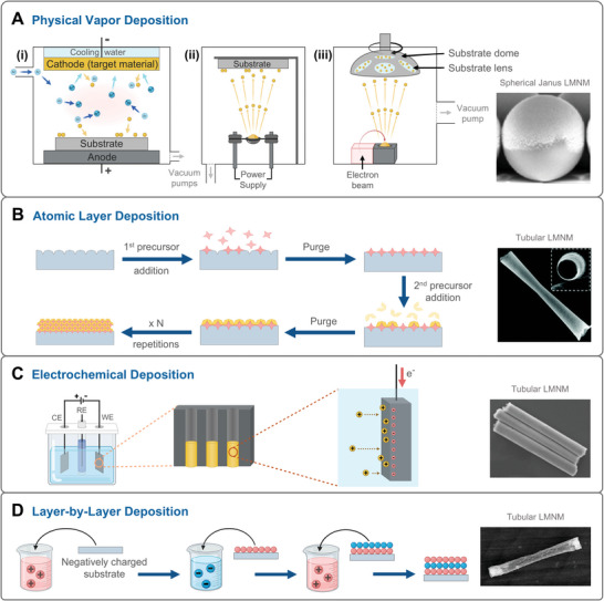
Main deposition techniques used for fabricating LMNMs. A) Physical Vapor Depositions: i) sputtering; ii) thermal evaporation; and iii) electron‐beam evaporation. B) Atomic Layer Deposition. C) Electrochemical deposition. D) Layer by Layer Deposition. SEM/TEM images were adapted with permission. (A)[ 83 ] Copyright 2021, Springer Nature, (B)[ 84 ] Copyright 2017, Royal Society of Chemistry, (C)[ 85 ] Copyright 2022, American Chemical Society, (D)[ 86 ] Copyright 2018, American Chemical Society.
2.1. Hydrothermal and Solvothermal
Hydrothermal (aqueous media) and solvothermal (non‐aqueous media) methods refer to processes where chemical reactions take place within a sealed vessel under high temperature and pressure,[ 58 ] as shown in Figure 2A. Hydrothermal synthesis offers the advantage of synthesizing LMNMs with controlled morphology, narrow size distribution, and low degree of agglomeration. Moreover, it can be used to prepare particles of a very wide range of materials with high purity and stability.[ 59 , 60 ] In general, during the hydrothermal process, the pressure inside the reactor increases with a temperature rise, leading to the formation of crystal growth along various morphologies. The heating temperature, pH, precursors, reaction time, solvent, and filling volume are critical factors that need to be considered when performing the synthesis.[ 61 , 62 ] Since temperature and reaction time affect the dissolution of the reagents and the nucleation process, these parameters enable the control of the crystalline phases and the resulting morphologies of the micromotors. An additional annealing step is sometimes performed after the hydrothermal reaction to increase the degree of crystallinity or to induce a change in the crystalline phase.[ 63 , 64 , 65 ] It has been previously demonstrated that the motion capabilities of photocatalytic micromotors are highly dependent on the crystalline properties of the semiconductor materials.[ 66 ]
Butterfly‐like shaped BiVO4, hollow Cu2O spheres or ZnO microneedles are some examples of LMNMs that can be obtained through hydrothermal synthesis.[ 7 , 67 , 68 ] Given that the hydrothermal process is relatively easy and simple to perform, it has been regarded as an ideal approach for large‐scale production of LMNMs. Moreover, it is considered more environmentally friendly than solvothermal synthesis as it does not require organic solvents.[ 59 , 60 ] The hydrothermal fabrication of micromotors with more complex structures may require the assistance of templates. There is a wide variety of templates that have been reported for the construction of specifically shaped LMNMs, such as polycarbonate and anodized aluminum oxide (AAO) membranes.[ 69 ] In addition, micelles are also considered to be good candidates as soft templates.[ 70 ]
2.2. Sol–gel
Sol–gel is a bottom‐up process that can be used to prepare a wide range of metal oxides, and it is also considered a cost‐efficient method for the preparation of LMNMs. In a typical sol–gel synthesis, the precursors containing ligands weaker than water, such as halides, sulfates, and nitrates, among others, are hydrolyzed to form a sol, which is a stable suspension of colloidal nanoparticles (NPs).[ 71 ] As the particles continue to hydrolyze, the sol turns into a porous gel. With solvent evaporation, the porosity of the gel decreases, and the hardness increases (Figure 2B).[ 72 , 73 , 74 ] Sol–gel method offers good control over the morphology, homogeneity, structure, and size of nanomaterials by finely tuning the stabilizers, temperature, reaction time, and corresponding precursors.
Silicon dioxide is one of the materials most used as a scaffold for manufacturing different types of MNMs, in particular the mesoporous silica. For instance, it has been widely employed to load enzymes and photocatalytic materials (optical/chemical‐powered MNMs) for biomedical applications. It is noteworthy to mention that, when SiO2 only acts as a template, it will be removed in further synthesis steps (e.g., chemical etching), leaving the desired structure of the micromotor.[ 56 ]
2.3. MACE
MACE has been recognized as an attractive way for the fabrication of silicon (Si) nanowires in the field of MNMs, especially for optical/electric‐powered MNMs. During the MACE process (Figure 2C), the Si substrate can be locally etched by the aqueous acid solutions, such as the mixture of HF and AgNO3. The galvanic displacement reaction between Ag+ ions and Si results in the formation of SiO2, which is later etched into SiF6 and removed by HF. Since the pits are created immediately at the same locations, Ag NPs sink into the pits and continue the further etching process, forming the Si nanowires on the substrate.[ 75 ] To obtain a larger diameter of Si nanowires/nanorods LMNMs, polystyrene spheres‐assisted MACE has been developed. Typically, a monolayer of polystyrene spheres is loaded onto the Si substrate and followed by a deposition of an Ag (or Au) thin layer. Then, the polystyrene spheres are removed by sonication before the MACE process, leaving arrays of holes.[ 76 ] Consequently, the area covered by noble metal will be digested by the etchant much faster than the non‐covered part, forming the Si rods/wires on the substrate.[ 77 , 78 , 79 , 80 ] Another method to acquire the defined diameter of Si rods/wires is the use of lithography techniques,[ 9 ] in which the patterns are transferred onto the surface of a Si substrate coated with a photoresist layer. During the lithography procedure, the irradiation source (UV light, laser, electron beam) alters the solubility of the exposed parts of the photoresist, and the most soluble part is dissolved later in the developing step.[ 81 , 82 ] The resulting Si nanowires are commonly used to fabricate the nano‐tree structured LMNMs.
2.4. Physical and Chemical Deposition Techniques
Deposition techniques refer to those methods that are based on depositing a material layer on the surface of a substrate. Depending on how the deposited materials convert into gas, physically or chemically, two main types of depositions are identified: PVD (Figure 3A) and CVD (Figure 3B).[ 87 ]
PVD techniques use physical evaporation to convert the material, including metals, alloys, or semiconductors, into vapor, which is then allowed to condense on the substrate to form a thin film.[ 87 , 88 ] Sputtering and thermal/electron beam evaporation are widely known PVD techniques for the synthesis of Janus‐structured MNMs. The main difference between these PVD techniques lies in how the target material is converted into its gaseous state. In sputtering, high‐energy argon (Ar) ions bombard the target material to eject atoms, while in thermal evaporation, the target material is heated in a crucible until it vaporizes. In electron beam evaporation, the target material is also placed in a crucible but is vaporized by bombardment with a high‐energy electron beam (Figure 3A).[ 80 , 87 ] Half‐coated Janus structures, such as Au/TiO2 and Au/SiO2 LMNMs, can be easily obtained by PVD techniques.[ 89 , 90 ] Furthermore, since the deposition technique has unbeatable advantages for the formation of asymmetric structures consisting of different components, it has been widely considered in the fabrication of optical/magnetic‐powered MNMs by simply sputtering magnetic metal materials (Ni, Fe, Co) onto the immobilized photoactive MNMs. On the other hand, CVD procedures involve the reaction of gas precursors, the formation of generated products, and the deposition of products onto a substrate. Among CVD techniques, Atomic Layer Deposition (ALD) is the most used method for the fabrication of LMNMs. We discuss it in more detail below.[ 87 , 91 ]
2.4.1. ALD
Contrary to other CVD techniques where the precursors are injected together into the chamber, in an ALD process, the precursors are introduced one by one. The target materials are deposited as a single atomic film onto the supports, and it consists of two stages: i) one of the gas precursors is introduced into the chamber and then it is chemisorbed by the substrate, occupying every available surface site, and thus, forming a reactive layer on its surface. ii) After purging the chamber, the second gas precursor is introduced, and it reacts with the chemisorbed one, producing a monolayer of the product directly on the substrate (Figure 3B).[ 80 , 91 ] Consequently, the thickness of the deposited material can be controlled by the number of cycles performed.
By selectively choosing the structure of the substrate material, ALD can realize the desired shape of MNMs. For instance, it is possible to use a spherical substrate material to obtain a homogeneous additional layer but only leave a small portion of the support material uncovered. This is because this small area would be in contact with the substrate during the deposition process and therefore no target material could be deposited. Taking advantage of this, the deposition of different layers of material that can respond to different external energy fields can be easily realized. Another interesting use of ALD is the design of tubular LMNMs in collaboration with templates.[ 92 ]
2.4.2. Electrochemical Deposition
Electrochemical deposition or electrodeposition has gained much attention for the fabrication of LMNMs in the last few years. This technique enables the deposition of metal ions from a solution onto a semiconductive or conductive substrate during a redox reaction occurring under the applied electric field (Figure 3C).[ 93 ] The electrochemical deposition follows the same basics and setup as electrochemical analysis. A typical electrochemical cell includes a working electrode (WE), a counter electrode (CE), a reference electrode (RE), and the electrolyte. During an electrochemical process, a reduction reaction happens in the WE (cathode), and the generated electrons transfer from the WE to the metal precursors in the solution, which are then converted into their metallic states and deposited on the WE.[ 80 , 94 ] Templates are broadly used in the electrodeposition method to achieve the target shape of LMNMs. To use a template as the WE, a membrane needs to be coated first with a thin layer of a metallic film to become conductive, and then, with a second layer of copper or silver as the sacrificial layer. Afterward, the metals, semiconductors, or polymers in the solution can be deposited into the membrane template during the electrochemical reaction.
Two main types of MNMs structures can be generated through the electrochemical deposition method: bimetallic nanorods and hollow microtubes. In the former case, different metals are sequentially deposited to form the templated nanorods, leading to asymmetric MNMs with spatially separated catalytic regions.[ 85 ] The resulting bimetallic rod‐like MNMs with asymmetric convex/concave tips are the ideal candidates for optical/acoustic‐powered MNMs.[ 95 ] In the latter case, the semiconductors and/or metals are sequentially formed on the inner wall of tubular‐like pores of the template to obtain the targeted MNMs with a multi‐component design.[ 96 , 97 ]
2.4.3. Layer‐by‐Layer
Layer‐by‐layer (LbL) deposition is another simple and feasible method that can also be used to deposit multiple layers. It consists of dipping a charged substrate in a solution containing molecules or ions of opposite charge. Through electrostatic interactions, these molecules attach to the surface and neutralize the charge of the substrate, thus reversing the electrical polarity of the surface. Then, the substrate can be dipped into another solution containing molecules with opposite charges compared to the previously formed layer, alternating between positive and negative charges (Figure 3D).[ 98 , 99 , 100 ] To date, LbL deposition has been primarily used for template‐assisted fabrication of MNMs, since a specific template is required as deposition substrate to obtain the desired shape.[ 101 , 102 ]
2.5. Other Fabrication Techniques
The synthesis of single‐ or multi‐engine LMNMs often involves the combination of two or more fabrication techniques, which are carefully selected based on the desired shapes and material properties. Various strategies can be employed in the fabrication of LMNMs, including microemulsions, Pickering emulsions, and 3D printing,[ 103 , 104 , 105 ] each offering unique advantages depending on the specific design requirements. For instance, 3D‐printed helical microstructures are widely used in the development of near‐infrared (NIR)‐driven/magnetically powered MNMs for various biomedical applications.[ 106 , 107 ] The typical fabrication methods used for the design of dual‐energy source‐powered MNMs based on each engine and the most representative morphologies have been included in Table 1 .
Table 1.
Typical fabrication approaches of different self‐propelled micro/nanomotors, and the corresponding representative morphologies.
| Types of MNM | Optical | Chemical | Magnetic | Acoustic | Electric |
|---|---|---|---|---|---|
| Typical fabrication approaches |
|
|
|
|
|
| Representative morphologies |
|
|
|
|
|
3. Dual‐Energy‐Powered LMNMs
Light is a versatile stimulus for inducing micromotor propulsion due to its easy accessibility, a wide variety of light sources, and ability to induce a rapid response. With such a vast diversity of parameters to be explored, LMNMs offer an unmatched variety of choices that can be tailored for specific functionalities. The most interesting property of light actuation is the easy modulation of wavelength, light intensity, and polarization. UV, a high‐energy light, has been widely used as the stimulus for LMNMs. The most investigated UV photoresponsive micromotors are based on the TiO2 and ZnO, due to the low cost and high activity.[ 89 , 108 , 109 ] To obtain the asymmetric distribution of generated ions during the photocatalytic reactions, one viable method is to combine the TiO2 or ZnO (active) with passive materials (e.g., SiO2, polymer). Nevertheless, in practical applications, especially in biomedical contexts, eco‐friendly and biocompatible energy sources are an essential factor to consider.
In comparison to UV radiation, visible light has proved to be harmless to human beings and represents a larger part of the electromagnetic spectrum, resulting in a wider choice of wavelengths, and ultimately granting better flexibility for desired applications. In order to initiate the photoreaction under the visible region, the optical properties of LMNMs need to be carefully regarded to fulfill the redox potential and the light absorption (bandgap ≈< 3 eV). For instance, WO3, g‐C3N4, BiVO4, Fe2O3, and Cu2O have been widely used for the fabrication of visible‐activated LMNMs according to their proper bandgaps (Figure 4 ). Furthermore, to enhance the potential biomedical applications of LMNMs, there is a strong demand for NIR light‐driven motors, as they operate within biological windows where tissues exhibit greater transparency. For NIR‐driven MNMs, temperature gradients generated by the NIR laser (via self‐thermophoresis) enable LMNMs to move in a fuel‐free environment, eliminating the reliance on toxic fuels.[ 101 ]
Figure 4.

Representative illustration of electromagnetic spectrum and commonly used photoresponsive materials.
Other light properties on the motion actuation of LMNMs, such as the intensity and polarization are also feasible ways to precisely control the movement of LMNMs.[ 8 , 110 ] It is well known that the intensity of light is directly proportional to the photon flux. Thus, increasing the intensity of incident light enriches the number of photons per unit area that are absorbed by micromotors, increasing the photocatalytic efficiency. In general, within a certain range of the light power (depending on the material being studied), the motion speed of LMNMs can be boosted due to a higher generated species concentration gradient (for self‐electrophoresis and self‐diffusiophoresis) and/or the local temperature (for self‐thermophoresis). It should be noted that excessive light intensity may also lead to structural damage, especially for hollow‐structured LMNMs, due to an excessive accumulation of overheated interior liquid.[ 70 ] Besides, manipulating the polarization state of light is also capable of precisely controlling the movement of LMNMs. For example, it has been reported that under parallel polarized light irradiation, an antimony selenide‐based core‐shell Sb2Se3/ZnO LMNM with one‐dimensional structure moves three times faster than that under perpendicular polarized light.[ 110 ]
While modulating optical properties is a viable way to achieve more controllable motion characteristics (e.g., speed and direction) of LMNMs, their motion efficiency and ability to penetrate physical barriers in biological media are still highly limited. To address this, integrating optical stimuli with additional energy inputs, such as chemical fuels, or magnetic, electrical, or acoustic fields, offers more possibilities for accomplishing tasks in real‐world applications, which has gained significant attention in recent years. This new generation of dual/multi‐energy powered LMNMs has the potential to overcome the intrinsic limitations of single‐stimulus systems, enhancing their responsiveness and adaptability to specific applications. In this section, we will examine key examples of optically powered dual‐energy LMNMs, including combinations such as optical/chemical, optical/magnetic, optical/acoustic, and optical/electric. Table 2 summarizes the advantages, challenges, and principal fabrication strategies of these combinations. Moreover, a comprehensive overview of employed experimental setups and the distinct functionalities they enable is provided in Figures 5 , 6 , 7 , 8 .
Table 2.
Advantages and disadvantages of dual‐energy‐powered micro/nanomotors and the corresponding typical fabrication strategies.
|
Optical/chemical
|
Optical/magnetic
|
Optical/acoustic
|
Optical/electric
|
|
|---|---|---|---|---|
| Pros |
|
|
|
|
| Cons |
|
|
|
|


Figure 5.

Representative illustration of optical/chemical‐powered MNMs and the typical motion modes. The inset indicates: an increase in chemical fuel concentrations accelerates the movement of LMNM; an increase in light intensity can lead to the acceleration, break, or reversal behavior of LMNM.
Figure 6.

Representative illustration of optical/magnetic‐powered MNMs and the typical motion modes. Insets: the upper panel presents the commonly used setups; the lower panel describes the functionalities that a magnetic field may provide, such as directionality and acceleration.
Figure 7.

Representative illustration of optical/acoustic‐powered MNMs and the typical motion modes. Insets: the upper panel presents the commonly used setups; the lower panel describes the functionalities that an acoustic field may offer, such as acceleration, brake, reverse, and collective behaviors.
Figure 8.

Representative illustration of optical/electric‐powered MNMs and the typical motion modes. Insets: the upper panel presents the commonly used setups; the lower panel describes the functionalities that an electric field may offer, such as rotation and acceleration.
3.1. Optical Actuation Combined with Chemical Fuels
It is well‐known that MNMs fuelled with chemical sources generate autonomous propulsion via the concentration gradient of product species or bubbles from the employed catalytic reactions.[ 111 , 112 , 113 ] Inspired by natural chemotaxis, efforts have been devoted to the development of artificial chemotactic MNMs in recent years. However, their precise motion control in chemical fuel systems still remains a challenge as they always tend to move toward regions with higher gradient concentrations. To achieve precise control over the movement of MNMs—including acceleration, braking, and reversing direction—coupling chemical activation with light actuation has proven to be highly effective, as illustrated in Figure 5. In conventional LMNMs, chemical fuel is primarily utilized to drive the photocatalytic reaction. In this section, however, we explore MNMs powered by both optical and chemical energy, where the chemical fuel can also propel the system in the absence of light. We present a comprehensive overview of these dual‐energy powered LMNMs, with a focus on material selection, the underlying chemical reactions, and the resulting motion behaviors.
3.1.1. Materials Selection
A variety of optical/chemical‐powered MNMs with Janus structure have been investigated, utilizing photoresponsive materials as the scaffold and incorporating a catalytic cap that reacts with the chemical medium. Different catalytic caps have been explored based on the specific chemical reactions involved. For example, when H2O2 is used as the chemical fuel, noble metals (Pt, Au) are commonly employed to catalyze the H2O2 decomposition.[ 52 , 114 ] However, since these noble metals can independently trigger the chemical reaction, it is crucial to assess the specific contribution of light when both stimuli are applied simultaneously. Mesoporous SiO2 is one of the most popularly used enzyme carriers, because of its bio‐combability, ease of surface modification, and obtaining different shapes and sizes.[ 115 ] However, as an insulator, silica lacks the ability to move autonomously. Therefore, the incorporation of silica with other photothermal materials, such as Fe3O4 NPs, Au, carbon, and polydopamine (PDA), among others, to fabricate the optical‐thermophoresis system has been widely developed for (bio‐)chemical/NIR‐light‐driven MNMs.
3.1.2. Chemical‐Powered LMNMs
In an optical/chemical‐powered system, light can act as an accelerator,[ 84 , 116 ] or a breaker, depending on whether the forces generated by the two stimuli act in the same or opposite directions. A pioneering study of dual optical/chemical Janus TiO2/Au/Pt micromotors was proposed by Chen et al.[ 34 ] In this work, the photoelectrochemical reaction on the TiO₂ side and H₂O₂ decomposition on the Pt side occur simultaneously, generating competing propulsion forces within the motor. By adjusting the UV light intensity, the photochemical reaction rates can be easily modulated, allowing for control over the dominant direction of motor movement (acting as an optical braking system). Likewise, chemical fuels can influence the movement of LMNM, e.g., adjusting the concentration of the reagents can readily modulate its motion speed. Table 3 summarizes additional notable examples of optical/chemical‐powered MNMs fabricated by different support materials.
Table 3.
Different combinations of optical energy sources with other stimuli for LMNMs. The abbreviations used in this table (from top to bottom): DMS: modified dendritic silica, C: carbon, CDT: chemodynamic therapy, WSP: water‐soluble conjugated polymer, PMOs: periodic mesoporous organosilicas, PS: polystyrene.
| Dual‐energy source | Materials | Morphology | Light range (wavelength) | Primary fabrication methods | Light‐induced motion mechanism | Role of the second energy source | Application | Refs. |
|---|---|---|---|---|---|---|---|---|
| Optical/chemical | Lipase‐DMS/C@Pt | Janus sphere |
NIR (980 nm) |
Sol–gel + Post‐grafting |
Self‐thermophoresis | Speed modulation | N/A | [145] |
| Cu2+1O | N/A |
Visible (450–750 nm) |
One‐pot chemical reaction | Self‐diffusiophoresis | Speed modulation | N/A | [5] | |
| Carbon‐MnO2 | Jellyfish‐like |
NIR (808 nm) |
Emulsion‐induced interface anisotropic assembly + Sol–gel | Self‐thermophoresis | Motion propulsion | CDT | [146] | |
|
TiO2/WSP/ GOx |
Janus sphere |
Visible (433 nm) |
Sol–gel + Pickering emulsion | Self‐diffusiophoresis | Speed modulation | N/A | [147] | |
|
SiO2@Au& PMOs |
Nanocube + core@shell nanosphere |
NIR (808 nm) |
Seed growth + Anisotropic island nucleation and growth | Self‐thermophoresis | Direction control | Cellular uptake | [119] | |
| TiO2/Au/Pt | Janus sphere |
UV (365 nm) |
Sol−gel + Sputtering | Self‐diffusiophoresis | Direction control | N/A | [34] | |
| Optical/magnetic | TiO2/Ni‐Au | Janus sphere |
UV (330−380 nm) |
Solvent extraction/ evaporation | Self‐electrophoresis | Direction control | N/A | [65] |
| Fe2O3/Au | Janus rod |
Visible (N/A) |
Electrochemical deposition | Self‐electrophoresis | Direction control | N/A | [31] | |
| TiO2/Fe | Janus sphere |
UV (330–380 nm) |
Sol−gel + Sputtering | Self‐electrophoresis | Direction control | N/A | [32] | |
|
Fe3O4/ BiVO4 |
Star shape |
Visible (N/A) |
Hydrothermal + Impregnation | Self‐diffusiophoresis | Direction control and sample recovery | Removal of yeast cells | [55] | |
| Fe3O4/C3N4 | Foam‐like |
Visible (N/A) |
Hydrothermal | Self‐diffusiophoresis | Direction control and sample recovery | Degradation of Tetracycline | [148] | |
| PS‐AgCl, or, TiO2, ZnO, Fe2O3 | Dimeric sphere |
UV (365 nm) |
Soften and fuse | Self‐diffusiophoresis | Direction control | N/A | [149] | |
| Fe2O3/TiO2 | Core‐shell peanut |
UV (365 nm) |
Hydrothermal + ALD | Self‐diffusiophoresis | Direction control | Degradation of 2,4‐ Dichlorophenoxyacetic acid | [51] | |
| CoO/TiO2 | Janus sphere |
Visible (400–700 nm) |
Sputtering | Self‐electrophoresis | Direction control | N/A | [54] | |
| ZnO/Ni | Janus tube |
UV (340–380 nm) |
ALD + Electrochemical deposition | Bubble propulsion | Direction control | N/A | [123] | |
|
Fe3O4@ TiO2/Pt |
Janus sphere |
UV (N/A) |
Hydrothermal + Sol–gel + Electron‐beam evaporation | Self‐electrophoresis | Direction control and speed modulation | Degradation of methylene blue | [150] | |
| Optical/electric | Si | Nanowire |
Visible (532 nm) |
MACE | Optomechanical effect | Rotation and direction control | N/A | [76] |
| Si | Nanowire |
Visible (532 nm) |
MACE | Electric polarisation | Motion control and synchronous alignment | Transmitting meaningful words | [142] | |
| Si | Nanowire |
Visible (532 nm) |
MACE | Induced dipole interactions | Assembling and disassembling behaviors | N/A | [57] | |
| TiO2‐Pt | Micro‐sphere |
UV (365 nm) |
Chemically coating + Sputtering | Self‐electrophoresis | Speed modulation | N/A | [130] | |
| SiO2‐Pt | Micro‐sphere |
Visible (625 nm) |
Sputtering | Self‐electrophoresis | Motion control along configurable pathways | N/A | [143] | |
|
Optical/ acoustic |
Au | Nanorod |
Mercury lamp (N/A) |
Electrochemical deposition | Optical radiation force breaking the equilibrium of acoustic force | Firework behavior | N/A | [35] |
| TiO2‐Au | Microbowl |
UV (365 nm) |
Electron‐beam evaporation | Self‐electrophoresis | Direction control and speed modulation | N/A | [140] |
As extensively reported, H2O2 is an efficient chemical fuel for powering MNMs. However, at high concentrations, H2O2 acts as a strong oxidant, potentially causing corrosion of metallic biomaterials, and even leading to the degradation of MNMs themselves.[ 117 ] Besides, it is also considered a cytotoxic agent at concentrations up to ca. 50 µM because it can oxidize the DNA, lipids, and proteins, which limits its applicability in biomedical environments.[ 118 ]
3.1.3. Biochemical‐Powered LMNMs
Enzymes have been widely recognized as a greener alternative energy source for powering MNMs due to their versatility, biocompatibility, and operations at mild reaction conditions. Nevertheless, enzyme‐driven MNMs also face the challenge of uncontrollable speed in stable physiological environments. The combination of enzymes with light‐driven motors presents an opportunity to achieve more controllable movement. For the architecture of artificial MNMs, which can enable both photocatalytic and biocatalytic reactions, specific enzymes need to be integrated into the photoresponsive carriers. The most widely researched enzymes include glucose oxidase (GOx), catalase (CAT), urease, acetylcholinesterase (AChE), and adenosine triphosphatase (ATPase). Recently, the multi‐enzyme engine MNMs have attracted considerable attention, for example, the cascade reaction of GOx and CAT. In this configuration, GOx breaks down β‐D‐glucose to H2O2, which then serves as fuel for the CAT‐driven bioreaction, ultimately leading to self‐propulsion. In this context, light can also be used to accelerate, break, or change the motion direction of enzyme‐based MNMs. For instance, Liu et al. presented a Janus SiO2@Au&periodic mesoporous organosilica (PMOs) MNM functionalized with GOx and CAT.[ 119 ] The obtained optical/chemical‐powered MNMs could realize self‐propelled motion based on self‐diffusiophoresis (from GOx and CAT side) and thermophoresis (from Au side) under only glucose solution or 808 nm NIR irradiation, respectively. Whereas, when the biofuel is considered as the dominant stimulus and additional NIR light is further introduced, a decelerating behavior can be observed due to the simultaneous application of opposite driving forces to MNM. The investigation of enzyme‐based optical/chemical‐powered MNMs, which can be remotely manipulated with an NIR optical break at fixed glucose concentrations, offers great potential for drug delivery application.
3.2. Optical Actuation Combined with Magnetic Fields
In the past decade, combining a light source with a magnetic field has proven to be an effective strategy for overcoming the intrinsic limitation of non‐directional motion in MNMs. Several excellent reviews have been published on the fundamentals of magnetically driven MNMs.[ 120 , 121 ] Therefore, in this section, we focus specifically on optical/magnetic dual‐source powered MNMs, providing a detailed methodological guide on their fabrication and design. This includes material selection, synthesis strategies, and key insights for future research. Moreover, we cover the experimental setups currently used in the field.
3.2.1. Setup and Materials Selection
In principle, the magnetic field can be generated by conventional permanent magnets or free electric currents.[ 120 , 121 , 122 ] Different experimental setups have been reported to combine magnetic fields with a light source, as shown in Figure 6. Up to date, the simplest method for magnetic steering of MNMs involves attaching a movable permanent magnet to the optical‐driven system. In contrast, using electromagnets provides more precise control over MNM motion by allowing adjustments to the horizontal or vertical orientation of the magnetic field. Similar to the previous optical/chemical‐powered MNMs, the idea behind the design of optical/magnetic‐powered MNMs is to integrate the photocatalytic and magnetic properties into a single device. Ni, Co, Fe, Fe2O3, Fe3O4, and alloys such as FeCo and NiFe, are the most broadly explored magnetic materials for developing dual‐responsive LMNMs. We summarized some examples in Table 3, such as Au‐Ni‐TiO2 Janus sphere,[ 65 ] TiO2‐Fe Janus sphere,[ 32 ] CoO/TiO2 Janus sphere,[ 54 ] ZnO‐Ni microtube,[ 123 ] g‐C3N4/Fe3O4@kapok fibre,[ 124 ] among others. Bare iron oxides (typically α‐Fe2O3 and Fe3O4 NPs) can be regarded as a promising hybrid photocatalytic/magnetic engine, because of their capability of responding to both light and magnetic field at the same time. α‐Fe2O3, so‐called hematite (weak ferromagnetic), with a narrow bandgap of ≈2.2 eV can be activated by visible light.[ 125 ] Nevertheless, its narrow band gap also leads to the fast recombination of excited electrons and holes, resulting in low photoactivity. In this regard, fabricating a heterojunction between hematite and other metals and/or semiconductors offers a more effective way to extend the lifetime of photogenerated carriers.
To design efficient optical/magnetic powered MNMs, the first important factor that needs to be taken into consideration is: does the light source and the magnetic field work independently or synergistically? In an optical/magnetic‐powered MNM system, when the light source provides propulsion, the magnetic field can serve three roles: remote directional control, enhancing electron transfer, or facilitating the recovery of MNMs. Conversely, when the magnetic component drives the LMNMs, the light, particularly NIR, can be used to provide photothermal or photodynamic therapy (PTT or PDT) in biomedical applications.
3.2.2. Optical and Magnetic Fields Operating Independently
As we mentioned above, when two energy sources are applied to MNMs simultaneously, one energy source contributes to the motion and the other to the function. For example, Fe3O4 NPs are widely recognized as materials with both highly efficient magnetic and photothermal properties, which usually have no interaction with each other. Owing to their superparamagnetic properties, Fe3O4 NPs are predominantly employed to provide directionality and recyclability during motion characterization under a magnetic field, especially in practical applications.[ 126 ] Pure magnetic metals, for example, Co and Ni, are not considered to be the ideal materials in environmental and biomedical utilizations, as they are susceptible to exhibiting high toxicity to cells and oxidative behavior in acidic/alkaline environments;[ 127 ] whereas, in this regard, Fe3O4 NPs are favored for their outstanding chemical stability and biochemical compatibility. Moreover, there is a consensus that nanosized Fe3O4 particles are important photothermal materials that can either convert the NIR light to generate a temperature gradient to propel the LMNMs or offer a heating environment for PTT. In the latter case, upon NIR light irradiation, the photothermal effect of Fe3O4 NPs can induce an increase in local temperature and further trigger the disease treatment in vivo or in vitro conditions. For instance, under the precise guidance of a rotating magnetic field and NIR irradiation of 808 nm (1 W/cm2), Fe3O4 NPs can be navigated to the targeted myotube and increase the local temperature up to ≈42 °C, enabling precise contraction of the myotube.[ 128 ] Moreover, the inactivation of bacteria and tumor cells is another common use of Fe3O4‐based magnetic/NIR powered MNMs,[ 129 ] which also relies on the cooperation of magnetically powered engine and photothermal effect. In addition to the heating ability, light irradiation is capable of triggering drug release in the target spot. Bozuyuk et al. reported a double‐helical Chitosan MNM able to self‐propel under a rotating magnetic field and release doxorubicin by switching on–off a UV light.[ 107 ] Another unparalleled common advantage of magnetic materials is the recycling of the used MNMs, which is a pivotal factor for practical application.[ 55 ]
3.2.3. Optical and Magnetic Field Working Synergistically
Concerning the synergistic effects, improvements in motor behavior can be mainly obtained from two mechanisms: i) the magnetic field influences the charge separation in photocatalytic LMNMs and ii) the magnetic field rectifies the zenith angle of LMNMs, as shown in Figure 6.[ 130 ] Very recently, Villa et al. presented a rod‐like TiO2/NiFe nanomotor with outstanding photocatalytic performance for phenol generation under UV light illumination in 0.05% H2O2 solution.[ 33 ] After applying an external homogeneous magnetic field, the nanomotors could not only align their motion direction with the direction of the magnetic field but also exhibit significantly enhanced velocities and photocatalytic performance. Authors proposed that the transfer of excited carriers from the TiO2 to the NiFe alloy of nanomotors was accelerated with the assistance of the magnetic field during the photocatalytic reaction process, thus, resulting in superior behavior. To the best of our knowledge, this is the first demonstration that a magnetic field can accelerate electron transfer in LMNMs. In fact, it has been widely recognized that the external magnetic field can improve the performance of photocatalysts by increasing their efficacy of light absorption, charge separation, and surface reactions.[ 131 ] Especially, in the case of the modulation of charge separation, the magnetic field is able to influence the photocatalytic systems through inducing magnetoresistance effect, spin polarization, and Lorentz force.[ 132 , 133 ] There remains significant potential for future research to investigate the motion behavior and underlying mechanisms of magnetic field‐assisted photocatalytic MNMs.
3.2.4. Multi‐Energy Source‐Powered LMNMs
The combination of multiple energy sources in LMNMs also have been explored, such as the combination of light energy with chemical fuel and magnetic fields. In the reported study on Pt/Fe2O3/quantum dots MNM,[ 134 ] each component served a different and complementary purpose, wherein Pt NPs decomposed H2O2 propelling the motor, quantum dots absorbed UV or visible light to improve catalytic activity, and Fe2O3 served as magnetic steering. Although unprecedented control over speed and position can be achieved, the described synthesis also involves multiple steps, which might be challenging depending on the task that MNMs are designed to perform. Nonetheless, the combination of several different energy modes remains promising, providing more opportunities for designing LMNMs capable of accomplishing complex tasks.
3.3. Optical Actuation Combined with Acoustic Fields
Ultrasound, as a pressure wave, has emerged as a promising method for achieving fuel‐free propulsion of MNMs. By applying acoustic waves, MNMs can achieve directional propulsion, offering a significant advantage in traversing biological media with high viscosity and ionic strength.[ 135 ] The strong penetration capabilities of acoustic waves allow for the effective movement of MNMs in complex environments, such as dense tissues or fluids, where traditional propulsion methods may struggle. To achieve effective acoustophoretic translational propulsion, it is essential to introduce density or shape asymmetry in the MNMs. Ultrasound‐induced motion can be classified into two types based on wave propagation: standing waves and traveling waves. Standing waves generate stable patterns that can trap or manipulate MNMs while traveling waves provide continuous propulsion by pushing the MNMs in the direction of wave propagation. More details on the actuation of sound waves have been discussed elsewhere.[ 95 , 136 , 137 ] To the best of our knowledge, there are many examples of acoustic/chemical and acoustic/magnetic propulsions been reported,[ 138 , 139 ] but the combination of a light source with an acoustic field is still in its infancy. So herein, we will introduce the important concepts in such combination, as well as highlight the possible advantages.
3.3.1. Setup and Materials Selection
The experimental setup to study the behavior of optical/acoustic‐powered MNMs is relatively simple. It involves placing a piezoelectric transducer beneath the sample substrate in a standard microscope equipped with light sources, enabling simultaneous optical and acoustic stimulation (Figure 7). Additionally, resonant cavities are often used as sample chambers in systems employing ultrasonic standing waves. These can be created by assembling a ring of a specific height (e.g., Kapton tape of known thickness) on the substrate (such as silicon, glass, or a metallic plate) and covering it with a glass slide.[ 95 ]
From the point of view of materials design, both the density (acoustic contrast) and shape of the MNMs are crucial for achieving effective acoustic propulsion. Simultaneously, for efficient light‐driven MNMs, material selection must be carefully aligned with the desired wavelength of the light source. Therefore, to successfully integrate acoustic and optical fields for dual‐source propulsion, both factors—acoustic properties and optical responsiveness—must be considered. Nanorods and cavity structures are commonly constructed to provide asymmetric shapes. The nanorods can be easily synthesized through template‐assisted electrodeposition approach companying with concave and convex ends. Besides, a cone‐shaped micromotor with Au nanoshells was reported to achieve fast perforation to a cell membrane under ultrasound propulsion (metallic materials + cone shape) and NIR light (photothermal effect of Au).[ 102 ] As acoustic waves can propagate deep into complex liquid media, their combination with NIR irradiation opens a new range of biological and electronic applications, from drug delivery and sensing to microfabrication and microchip operations.[ 35 , 140 ]
3.3.2. Motion Manipulation
Typically, acoustic fields mainly afford the function of motion manipulation when integrated with an optical system. In the presence of acoustic waves, the nanorods are levitated to the midplane of the cell and driven autonomously through their asymmetric structure. When thousands of MNMs are clustered together, collective behavior can be observed due to the hydrodynamic interactions between them. Zhou et al. exploited this interesting aggregation/separation behavior of acoustic‐driven Au nanorods and further combined it with light irradiation to achieve more precise manipulation.[ 35 ] Au nanomotors aggregate and form the cluster in an acoustic field (ca. 3 MHz of frequency and 10 V of applied voltage); while the Au nanomotors at or near the edges of the cluster move away upon light irradiated. This fireworks behavior is attributed to the additional optical forces breaking the equilibrium in the nodal plane created by acoustic radiation forces. Moreover, by adjusting the angle of light incidence, the spot can be selectively diffused, which opens up more possibilities for motion control in MNMs.
The speed and direction of MNM motion can also be easily adjusted by changing the direction of the acoustic and optical propulsive forces. For example, adjusting the frequency, phase, and amplitude of an acoustic wave can re‐program the position of the nodes of MNMs.[ 26 ] Yet, real‐time and precise control still remains a challenge under ultrasound conditions. Alternatively, the manipulation of light position or light‐responsive material structures can realize the easier motion control of MNMs. The propulsion direction of a light‐driven material is determined by its self‐electrophoretic direction, which can be switched by changing the electron transfer pathway (Figure 7). For instance, two different configurations of microbowl motors made of TiO2 and Au were designed, depending on the location of the Au coating (inner or outer).[ 140 ] The oscillations of the sharp edges in microbowl motors enable the movement induced by second‐order acoustic streaming flow, regardless of the TiO2 or Au position. When the UV light was switched on at the same time, the photochemical reaction and catalytic H2O2 decomposition reaction took place at the TiO2 and Au sides, respectively, resulting in the self‐phoretic motion always directed to the TiO2 side. As a result, behaviors such as braking, acceleration, and direction reversal can be achieved by adjusting the position of Au/TiO₂ and varying the light intensity.
3.4. Optical Actuation Combined with Electric Field
The directionality control of LMNMs can also be achieved by combining light with electric fields (E). It is well‐known that electric fields operating at direct current (DC) and alternating current (AC) enable precise manipulation and actuation of MNMs.[ 135 ] Two propulsion mechanisms have been proposed for the motion of MNMs under AC electric fields: self‐dielectrophoresis and induced‐charge electrophoresis.[ 24 ] The feasible approach to steering the motors toward the patterned route is to adjust the applied AC and DC electric fields on both, the x‐ and y‐axes (sequence and duration).[ 141 ] Taking advantage of this, the application of an electric field in a light‐driven system is a viable way to overcome the random motion of LMNMs for practical application. The schematic of a commonly used setup is shown in Figure 8.
3.4.1. Modulation of LMNM‐Electric Field‐Interaction
To achieve the light‐semiconductor‐electric configuration, Liang et al. designed an optical/electric setup for reconfigurable manipulation using Si nanowires.[ 76 ] Si nanowires were dispersed in deionized water and dropped in a quadruple microelectrode consisting of 100 nm of Au and 5 nm of Cr on glass. Under dim conditions (without laser), the LMNMs exhibited consistent cofield rotation in a range of AC frequency from 5 kHz to 2 MHz. While under laser irradiation (532 nm, 4 mW), the acceleration, deceleration, stop, and reversal of rotation chirality of motors could be readily accessed by manipulating the AC frequency, which can be attributed to the enhanced electrical conductivity of Si under laser excitation. Additionally, the same optoresponsive rotation phenomena were observed by adjusting the laser power, the diameter, and the length of Si nanowires. Theoretical analysis revealed that this phenomenon was caused by tuning the imaginary part of the electric polarization of LMNMs. Furthermore, the authors later studied the optical effects on the real‐part (in‐phase) polarization of the Si nanowires.[ 142 ] The manipulation of electro‐alignment could be obtained by solely controlling the light intensity. In contrast to the previous work, the tuneable in‐phase polarization can not only precisely control the angular position of a LMNM, but also align the orientation of motor arrays.
3.4.2. Electric Field Rectifying Orientation of LMNMs
It is worth noting that in addition to manipulating the motion direction, applying an AC field also can enhance the motion speed of LMNMs. An unexpected synergy on the movement of LMNMs induced by UV light/AC field was reported by Xiao et al.,[ 130 ] using a simple TiO2‐Pt dielectric‐metal Janus structure. The results indicated that 90% of the increase in the speed of a micromotor can be obtained under the combined sources rather than simply adding up the speed powered by either source. The authors demonstrated that when the LMNM was solely exposed to light irradiation, it moved near a substrate at a zenith angle of <90°, which reduces its velocity. This phenomenon is the so‐called tilting‐induced retardation and is likely due to the propulsive force vector of MNMs being perpendicular to its equator, which is decomposed into the vertical and horizontal components. As a result, only part of the force can be utilized to drive the particles to move forward. Nevertheless, when an AC electric field was applied to the system perpendicularly, the zenith angle of the LMNM could be rectified by the E field to be vertical to the substrate, thus facilitating the speed.
3.4.3. Setup Design
Besides the light and AC field, substrate modulation is another viable approach for realizing LMNM programmable optoelectronic steering. For example, a photoconductive substrate has been designed with a layer of hydrogenated amorphous silicon (a‐Si:H) on a glass slide together with indium tin oxide (ITO) coating.[ 143 ] Upon the red light (625 nm) illumination, the substrate generated nonuniform electric fields that attain a maximum at the edge of the exposed light area. The employed LMNM, SiO2‐Pt Janus particle, self‐propelled following the edge of light pattern due to the positive dielectrophoresis (DEP). Notably, this work is distinct from the typical optoelectronic tweezers (OET) operation, although they share the same concept of light‐induced nonuniform electric fields. Two reasons have been indicated: i) the manipulated target was different−using LMNMs instead of passive micro‐objects; and ii) the LMNM was self‐propelled, so the light acted as guidance rather than forcing. Regarding the OET,[ 144 ] and the photovoltaic optoelectronic tweezers (PVOET), being highly dependent on the specific substrates and devices rather than materials, we will not discuss them further; as it is beyond the scope of this review.
After a comprehensive literature survey, we found that the studies of optical actuation combined with electric fields are still rare. However, as we discussed above, the combination of these two energy sources holds many advantages for precise control of LMNMs. Therefore, researchers are encouraged to design more efficient optical/electric‐powered MNMs systems based on a holistic understanding and implementation of fundamentals of both light and electric fields. In addition, simplifying the experimental setup to make it easier for practical applications is also desirable.
4. Biomedical Applications
Biomedical applications have attracted significant interest in the research of MNMs. However, the development of self‐electrophoresis‐based LMNMs in complex biological scenarios still remains challenging, such as the reduction of movement velocity in high ionic strength environments. To this end, researchers have endeavored to investigate the LMNMs with enhanced ion tolerance ability, for example, the coating of surface polyelectrolyte layer,[ 151 ] increasing the porosity,[ 152 ] and optimizing the dimension of LMNMs.[ 64 ] In this context, the dual‐energy‐powered LMNMs provide superior motion control and actuation compared to single‐engine LMNMs, making them highly promising for a wide range of applications. In this section, we highlight the most representative examples of dual‐energy source‐powered LMNMs in biomedical applications and the unique advantages they offer for specialized applications, such as PTT, PDT, and drug delivery. It is worth noting that in this section the optical source, such as NIR light, is predominantly used to induce the photothermal effect of LMNMs for therapeutic treatments.
4.1. PTT
It is well known that the LMNMs can be propelled by a local temperature gradient under light illumination through self‐thermophoretic mechanisms.[ 153 ] The photothermal effect of LMNMs not only enables motion by generating asymmetric thermo‐osmotic flow but also can be used for phototherapeutic treatment in biomedical scenarios. In brief, during thePTT process, the MNM is propelled to the target location by means of magnetic actuation or acoustic propulsion, as the self‐thermophoretic mechanism usually lacks directionality. Then it converts the photon energy to heat in the presence of an external light source, ultimately killing the cancer cells (Figure 9A).[ 154 ] The mechanism is that, since cancer cells are less tolerant to high temperatures than healthy cells, after 10 min at temperatures between 42 and 46 °C (or even higher), cancer cells will be irreversibly damaged.[ 155 ] A PTT process of MNMs consists of two steps: the MNM moves to the target site and the PTT is triggered. As we mentioned above the first step can be achieved in various ways, whereas the second step is solely controlled by the light source.
Figure 9.

Schematic illustration of dual‐energy source‐powered MNMs in biomedical application. A) Photothermal therapy (PTT). Fe3O4, Au, polydopamine (PDA), transition metal sulfides (TM sulfides), carbon, and graphene are the commonly used photothermal materials. NIR light used in biomedical applications normally includes the NIR‐I (750–900 nm) and NIR‐II (1000–1700 nm) regions. B) Photodynamic therapy (PDT). Two types of ROS can be generated from the PDT process: type‐I (•OH, O2 •− and H2O2) and type‐II (1O2). Upconversion nanoparticles (UCNPs) are promising to be integrated into the MNMs to achieve efficient PDT treatment. C) Drug delivery and release. Magnetic or acoustic fields are utilized to actuate the LMNM, and the light source is used to trigger the drug release.
In terms of the light source, compared to UV and visible regions, NIR light holds great promise for biomedical applications due to better biological penetration and relatively low damage to the tissues. Since the traditional first NIR region (NIR‐I, 750–900 nm) only shows the shallow tissue penetration depth in vivo application, the ability of the second NIR window (NIR‐II, 1000–1700 nm) to overcome high tissue scattering is of increasing interest nowadays. It has been reported that to cause the same damage to cells, the laser intensity of 808 nm (NIR‐I) irradiation would have to be twice that of 1064 nm (NIR‐II) irradiation.[ 156 ] The commonly used materials for PTT include Fe3O4 NPs, Au, carbon, Pt, graphene, PDA, Ga, Ti2O3, and transition metal sulfides (TM sulfides, Fe1‐xS, Cu2‐xS, CoS2).[ 153 , 157 ] Cu9S8, particularly, has drawn much attention recently for PTT because of its plasmonic effect under NIR‐II irradiation.
Up to now, the hybrid magnetic‐assisted PTT is the most developed system as it shows an unrivaled potential in its inherent magnetic field orienting capability, which can be achieved by simply adding the magnetic materials to the photothermal materials. It is worth mentioning that the decoration of MNMs with Fe3O4 NPs can realize the magnetic and photothermal response at the same time.[ 154 ] Besides, ultrasound has been extensively used in biomedical applications due to its favorable tissue penetration capability, exceeding 10 cm). The speed of acoustically actuated MNMs can be manipulated by the power controller to reach the specific sites for PTT treatment.[ 158 ] In addition to the commonly investigated acoustic radiation propulsion force, ultrasound can also be used to trigger mechanoluminescent materials to achieve persistent luminescence, which may serve as an internal NIR source to activate photothermal materials, such as PDA, producing a mild photothermal treatment.[ 159 ]
In recent years, synergistic electrodynamic‐photothermal‐antibiotic therapies have been proposed by Li's group. They developed Janus pyroelectric NPs capped with PDAs that could be propelled by thermophoretic force upon NIR irradiation. Meanwhile, the built‐in pyroelectric field generated by pyroelectric tetragonal BaTiO3 (tBT) NPs affects membrane potentials, promoting the internalization of tumor cells. Furthermore, the loading of camptothecin (CPT) or ciprofloxacin (CIP) realized the desirable synergistic effect of pyroelectric dynamic therapy/PTT/chemotherapy.[ 160 , 161 ]
4.2. PDT
PDT is another valuable application of MNMs for treating malignant cells, infections, and other diseases. The process requires three key elements: a light source, photodynamically active materials (photosensitizers), and the generation of cytotoxic reactive oxygen species (ROS).[ 162 ] Upon activation by light, the photosensitizer produces ROS, which induces cell damage and death in targeted areas, as illustrated in Figure 9B.[ 163 ] The use of MNMs in PDT offers the potential for precise delivery of the photosensitizer to specific locations, improving the efficiency and selectivity of the therapy while minimizing damage to healthy tissues. In PDT process, two types of photochemical reactions can occur.[ 164 ] In type‐I, proton or electron transfer generates oxygenated reactive species such as superoxide anion (O2 •−), hydroxyl radical (•OH), and peroxide (H2O2). In type‐II, energy transfer results in the formation of singlet oxygen (1O2). The process begins when the photosensitizer is excited by light irradiation, typically from a NIR laser, which transfers the light energy to surrounding oxygen molecules, producing ROS. These ROS, in turn, induce cytotoxic effects that effectively kill tumor cells. Nevertheless, it is well known that the lifetime of 1O2 is very short (<40 ns),[ 165 , 166 ] which limits its diffusion distance and hampers further practical application. To improve the PDT efficiency, the design of directionally controllable MNMs to the target sites is expected. Similar to the PTT process, the integration of a magnetic field or acoustic field is capable of realizing remotely targeted transportation of MNMs. Additionally, enzyme‐powered nanomotors are also developed for biocompatible cancer treatment. For example, in a photothermal interference (PTI) urease‐modified PDA nanomotor, where urea decomposition generates self‐propulsion, biocompatible and biodegradable PDAs are used to induce photothermal effects in the NIR region.[ 167 ]
Since the activation of photosensitizer molecules occurs predominantly in UV and visible regions, PDT of large or internal tumors is highly restricted. To address this limitation, the incorporation of upconversion nanoparticles (UCNPs) with MNMs has been developed to enable efficient PDT in these regions, upon NIR illumination. UCNPs refer to the NPs that can convert long‐wavelength excitation to shorter‐wavelength emission via multiphoton absorption processes. Chen and co‐authors fabricated a nanomotor with UCNP/mesoporous silica core/shell structure,[ 168 ] half‐covered by an Au layer and incorporating surface modifications by photosensitizer, Raman reporter, and CAT. The resulting MNMs could move by the catalytic H2O2 decomposition of CAT, which is then facilitated by NIR light. The existence of UCNPs converts the NIR light source into visible light, which further activates the photosensitizer to generate ROS for PDT treatment. In fact, the combination of UCNPs and photosensitizer has been widely investigated for PDT over the past decades.[ 169 , 170 ] However, the exploration of introducing UCNPs/photosensitizer into LMNMs is still scarce, which will open an enlightened path for future biomedical applications.
4.3. Drug Delivery and Release
In general, the ability of drug loading, accurate transportation, and on‐demand drug release are the main factors in evaluating the effectiveness of an MNM. Since the self‐electrophoresis mechanism over LMNMs would be impacted by the highly ionic nature of the biofluids, photocatalytic propulsion is not ideal for drug delivery. For this reason, much effort has been devoted to the study of magnetically and acoustically‐driven, light‐triggered drug delivery/release systems (Figure 9C).[ 171 ] Among the magnetically actuated drug delivery MNMs, the helical shape gains considerable interest owing to its high efficiency of magnetic torque for microscale actuation.[ 106 , 107 , 172 , 173 ] To improve the ability of drug loading, porous structures are extensively employed as support materials, such as the most popular mesoporous silica.[ 174 ] In particular, MCM‐41 (Mobil Composition of Matter) is of more interest because of its hexagonal ordered pores, adjustable pore size, high specific surface area, and its ability to enhance the solubility of hydrophobic drugs. Similarly, metal‐organic frameworks (MOFs) with nanoporous coordination polymers are also proven to be good candidates for drug delivery applications.[ 175 ] The addition of magnetic materials (such as Fe3O4 NPs) into the construction of the basic frames of MOFs is a direct approach to achieving magnetic properties for MNMs. However, premature drug release is always the primary drawback for many MOF‐based drug delivery systems. To address this drawback, the synthesis of core/shell MOF/inorganic structures has been widely explored, which offers a versatile system for intelligent targeted therapy.
As we mentioned above, unlike magnetic and acoustic fields, light irradiation in drug delivery and release systems primarily controls the drug release step. By switching on–off the light source, on‐demand drug release can be easily achieved. For instance, magnetically driven carbon nanocoil/Fe3O4 helical nanomotors loaded with anticancer drug doxorubicin (DOX) have been shown to effectively release DOX in a short‐term under NIR irradiation, due to the sensitive photo‐response of carbon nanocoil to NIR light.[ 172 ] This combination of magnetic propulsion and light‐triggered release offers a promising strategy for targeted cancer therapy.
5. Conclusions and Outlook
The field of LMNMs has significantly advanced in recent years, particularly in terms of actuation, controllability, and collective interactions. Researchers are now focused not only on assessing the performance of LMNMs in real‐world applications but also on understanding the underlying mechanisms. In this Review, we highlighted the advantages of dual/multi‐source‐powered LMNMs and offered guidelines for designing LMNMs tailored to specific applications. While substantial progress has been made, we believe there is much to explore regarding the potential and benefits of the next generation of dual‐responsive LMNMs. Here, we discuss the current challenges and future opportunities in this evolving research area.
1) Designing dual‐energy‐powered LMNMs for complex environments.
A significant challenge for LMNMs is navigating through highly complex media. In real‐world applications, these LMNMs should be able to operate in physiological environments containing various components, such as ionic species, proteins, and bloodstreams. These elements increase the viscosity of the medium, potentially disrupting the self‐generated gradients required for propulsion. To address this, enhancing the intrinsic structural porosity of LMNMs is a promising strategy to improve their tolerance to ionic environments and maintain efficient propulsion under such challenging motion conditions.[ 152 ] Since MOFs can accommodate ions within their porous crystal structures, they help minimize the impact of complex media on the propulsion of MNMs. In fact, MOF‐based MNMs have shown great promise in both environmental and biomedical applications due to their high porosity and tunable structures. However, the development of light‐assisted MOF‐based MNMs remains limited, as pristine MOFs are inherently poor light‐harvesting materials. Overcoming this limitation by integrating more efficient light‐absorbing components or optimizing MOF structures for better photoreactivity could unlock new possibilities for these systems in complex environments. To address this, photoresponsive MOFs can be designed by incorporating photoswitchable or photochromic molecules, making them more suitable for light‐driven applications. The fabrication of MNMs that combine photoresponsive MOFs with other materials, such as magnetic, electrical, or acoustic components, offers considerable potential for future research and development, paving the way for more versatile and efficient dual‐responsive LMNMs. Similarly, other porous structures, such as covalent organic frameworks (COFs), hydrogen‐bonded organic frameworks (HOFs), and zeolites may also emerge as promising candidates for a new class of LMNMs. Additionally, the coating of LMNMs with biocompatible polymers, such as polycaprolactone and poly lactic‐co‐glycolic acid, has recently been demonstrated to enable their propulsion under diluted blood conditions.[ 176 ] Furthermore, biocompatible co‐catalysts such as Zn and Mg, which serve as vital trace elements for enzymatic and metabolic processes in the human body, are promising candidates for fabricating multicomponent LMNMs. Hence, refining the existing strategies to construct LMNMs with high tolerance and biocompatibility for complex biomedical contexts is essential to broaden the applications of MNMs.
2) The integration of UCNPs into LMNMs.
UCNPs have been widely explored for in vivo imaging, sensing, and thermometry due to their excellent ability to absorb multiple photons in the NIR region and emit visible light. However, their integration with LMNMs remains relatively unexplored.[ 177 , 178 ] While UCNPs have been successfully incorporated into LMNMs for particle tracking,[ 179 ] this only scratches the surface of their potential. Future studies could focus on more advanced applications, such as combining UCNPs with dye‐based LMNMs for active sensing and imaging across different wavelengths, rather than limiting them to passive detection.
3) The development of advanced artificial intelligence (AI, machine learning) for LMNMs.
The synthesis of LMNMs with highly effective properties has always intrigued researchers. However, in such an enormous database, relying solely on human investigations is not efficient as there are many factors, such as material types, structures, and fabrication methods. To address this issue, machine learning (ML) offers a more feasible path to identify data and generate the material‐structure‐property relationships via using algorithms, thus reducing time and homogenizing data across various groups. This approach has been already implemented in electrocatalytic and photocatalytic studies,[ 180 , 181 ] yet it still needs to be further elaborated in the study of LMNMs. Collecting a comprehensive database of LMNMs and then training AI algorithms to narrow down candidates is an excellent prospect to achieve LMNMs with improved specific features, such as higher speeds, more directional motion, and more environmental sustainability. In addition, when LMNMs are exposed to a complex environment, correctly identifying the targets throughout the tracking period is not an easy task, as the tracking programs may confront difficulties in distinguishing LMNMs from objects in the media that are similar in shape/size to them, especially for the nanoscale motors. For instance, a deep‐learning U‐Net architecture was successfully utilized for tracking tubular MnO2‐laccase bubble‐propelled MNMs to differentiate them from surrounding bubbles.[ 182 ] Therefore, researchers are encouraged to develop ML models that are capable of tracking small‐size and high‐speed LMNMs in dense environments.
4) Fabrication reproducibility of LMNMs.
A common issue in LMNM research is the lack of detailed descriptions of fabrication processes, especially for wet chemical methods. For example, providing the exact volumes of reagents and reactors (or their volume ratios) in hydrothermal reactions is crucial, as these ratios significantly impact the pressure generated during synthesis. Similarly, other experimental parameters should be reported with as much clarity as possible to ensure reproducibility. Including sufficient SEM/TEM images to verify the target morphology is also essential for validating the results. As the field of LMNMs rapidly advances, comprehensive and transparent reporting is key to guiding future research and ensuring reproducibility across laboratories.
5) Overcoming the challenges of dual‐source powered LMNMs in real‐world usability.
As discussed in this review, combining optical actuation with another stimulus offers significant advantages over light excitation alone. While optical/chemical and optical/magnetic‐powered MNMs have been the most studied, optical/electric and optical/acoustic systems require further exploration. Despite promising proof‐of‐concept studies on dual‐energy‐source‐powered LMNMs, real‐world applications remain in their early stages. The primary goal of integrating a second energy source is to address the limitations of light‐driven MNMs in practical scenarios. To advance their real‐life usability, comprehensive testing is needed, particularly regarding biocompatibility, motion controllability, directionality in biological environments, and tissue permeability. Only by overcoming these challenges can LMNMs transition from laboratory studies to effective real‐world applications in fields such as biomedicine and environmental remediation. H2O2, as a common fuel for chemical‐driven MNMs, is not desirable for biomedicine as it causes oxidative stress and protein denaturation at high concentrations. Therefore, in the development of optical/chemical‐powered MNMs, researchers are encouraged to explore more biocompatible fuels, such as water, urea, glucose, and stomach acid.
In optical/magnetic actuation systems, while the use of movable permanent magnets is the most straightforward way of applying magnetic guidance to LMNMs, the accuracy and repeatability of experiments are greatly dependent on the manipulation of the operator. In contrast, electromagnetic devices provide a more stable and programmable approach to generating a magnetic field on demand. Nonetheless, it is noteworthy that the conversion of magnetic energy to heat radiation may occur during long‐term experiments, thus consequently affecting the practical application.
For optical/acoustic actuation, acoustic waves are predicted to propagate well under complex media without being affected by ion concentration or the presence of proteins, favoring medical applications. However, steering individual MNM for specific tasks remains challenging, particularly in optical/acoustic systems, where ultrasound is applied globally, limiting precise control. Nonetheless, it is evident from this review that significant advances can be anticipated for dual‐energy‐powered LMNMs, positioning them as the next generation of artificial micromachines. We are optimistic that ongoing research efforts will resolve the remaining challenges and fully translate this field into real‐world applications in the near future.
Conflict of Interest
The authors declare no conflict of interest.
Acknowledgements
The research was funded by the European Union (ERC, PhotoSwim, 101076680). Views and opinions expressed are however those of the author(s) only and do not necessarily reflect those of the European Union or the European Research Council. Neither the European Union nor the granting authority can be held responsible for them. This publication is also part of the grant PID2022‐136886OA‐I00 financed by MCIN/AEI/10.13039/501100011033/ FEDER, UE. K.V. acknowledges the support from the Spanish Ministry of Science (MCIN/AEI/10.13039/501100011033) and the European Union (Next generation EU/PRTR) through the Ramón y Cajal grant, RYC2021‐031075‐I. Y. C. acknowledges the support from “Juan de la Cierva Grant” JDC2023‐051508‐I, funded by MICIU/AEI/10.13039/501100011033.
Biographies
Yufen Chen is a postdoctoral researcher affiliated with the Institute of Chemical Research of Catalonia (ICIQ, Spain). She received her Ph.D. degree from the Universitat Politècnica de Catalunya, Spain, in 2023. Currently, her research focuses on the design, synthesis, and applications of photocatalytic micro/nanomotors, especially in the visible and near‐infrared light regions.

João Marcos Gonçalves is a postdoctoral researcher at the Institute of Chemical Research of Catalonia (ICIQ, Spain), holding a Marie Curie fellowship. He received his Ph.D degree from the University of São Paulo (Brazil) in 2020 with a 6‐month stay at the University of Aveiro. His research focuses on the combination of light‐driven nano/micromotors and luminescent materials, especially lanthanoid‐doped nanoparticles.

Rebeca Ferrer Campos received her BCs and MSc in chemistry and nanoscience from the University Rovira i Virgili. She is currently pursuing her Ph.D. degree in chemistry at the Institute of Chemical Research of Catalonia (ICIQ), under the supervision of Prof. Katherine Villa. Her main research focuses on designing and developing photocatalytic micro/nanomotors for different applications.

Katherine Villa completed her Ph.D. in Chemistry at the Autonomous University of Barcelona. She currently leads the “Advanced Photocatalytic Materials ” group at the Institute of Chemical Research of Catalonia (ICIQ). Her scientific trajectory has been recently recognized with the EuChemS Lecture Award by the European Chemical Society and the Young Researcher Award by the Spanish Royal Society of Chemistry. Furthermore, Prof. Villa has secured international competitive funding, including a prestigious ERC Starting Grant 2022 for her project “PhotoSwim”. Her research interests include light‐driven micro/nanomotors, nanomaterials, renewable energy, and environmental remediation.

Chen Y., Gonçalves J. M., Ferrer Campos R., Villa K., Dual‐Energy Integration in Photoresponsive Micro/Nanomotors: From Strategic Design to Biomedical Applications. Small 2025, 21, 2410901. 10.1002/smll.202410901
References
- 1. Dey K. K., Angew. Chem., Int. Ed. 2019, 58, 2208. [DOI] [PubMed] [Google Scholar]
- 2. Xu L., Mou F., Gong H., Luo M., Guan J., Chem. Soc. Rev. 2017, 46, 6905. [DOI] [PubMed] [Google Scholar]
- 3. Šípová‐Jungová H., Andrén D., Jones S., Käll M., Chem. Rev. 2020, 120, 269. [DOI] [PubMed] [Google Scholar]
- 4. Zhou D., Zhuang R., Chang X., Li L., Research 2020, 2020, 6821595. [DOI] [PMC free article] [PubMed] [Google Scholar]
- 5. Wang Q., Dong R., Yang Q., Wang J., Xu S., Cai Y., Nanoscale Horiz. 2020, 5, 325. [Google Scholar]
- 6. Villa K., Chem. Commun. 2023, 59, 8375. [DOI] [PMC free article] [PubMed] [Google Scholar]
- 7. Yuan X., Ferrer‐Campos R., Garcés‐Pineda F. A., Villa K., Small 2023, 19, 2207303. [DOI] [PubMed] [Google Scholar]
- 8. Du S., Wang H., Zhou C., Wang W., Zhang Z., J. Am. Chem. Soc. 2020, 142, 2213. [DOI] [PubMed] [Google Scholar]
- 9. Dai B., Wang J., Xiong Z., Zhan X., Dai W., Li C. C., Feng S. P., Tang J., Nat. Nanotechnol. 2016, 11, 1087. [DOI] [PubMed] [Google Scholar]
- 10. Debata S., Panda S. K., Trivedi S., Uspal W., Singh D. P., Nanoscale 2023, 15, 17534. [DOI] [PubMed] [Google Scholar]
- 11. Peng X., Chen Z., Kollipara P. S., Liu Y., Fang J., Lin L., Zheng Y., Light Sci. Appl. 2020, 9, 141. [DOI] [PMC free article] [PubMed] [Google Scholar]
- 12. Ding H., Chen Z., Kollipara P. S., Liu Y., Kim Y., Huang S., Zheng Y., ACS Nano 2022, 16, 10878. [DOI] [PMC free article] [PubMed] [Google Scholar]
- 13. Li X., Shi Y., Pan T., Lu D., Zhu G., Xiong J., Wang D., He Z., Huang J., Xin H., Laser Photonics Rev. 2024, 18, 2300480. [Google Scholar]
- 14. Shi Y., Wang D., Xiao Y., Pan T., Lu D., Zhu G., Xiong J., Li B., Xin H., Laser Photonics Rev. 2022, 16, 2200533. [Google Scholar]
- 15. Xiong J., Shi Y., Pan T., Lu D., He Z., Wang D., Li X., Zhu G., Li B., Xin H., Adv. Sci. 2023, 10, 2301365. [DOI] [PMC free article] [PubMed] [Google Scholar]
- 16. Xin H., Zhao N., Wang Y., Zhao X., Pan T., Shi Y., Li B., Nano Lett. 2020, 20, 7177. [DOI] [PubMed] [Google Scholar]
- 17. Pan T., Shi Y., Zhao N., Xiong J., Xiao Y., Xin H., Li B., Adv. Funct. Mater. 2022, 32, 2111038. [Google Scholar]
- 18. Zhu G., Xiong J., Li X., He Z., Zhong S., Chen J., Shi Y., Pan T., Zhang L., Li B., Xin H., Light Sci. Appl. 2024, 13, 258. [DOI] [PMC free article] [PubMed] [Google Scholar]
- 19. Weibel D. B., Garstecki P., Ryan D., DiLuzio W. R., Mayer M., Seto J. E., Whitesides G. M., Proc. Natl. Acad. Sci. USA 2005, 102, 11963. [DOI] [PMC free article] [PubMed] [Google Scholar]
- 20. Yasa O., Erkoc P., Alapan Y., Sitti M., Adv. Mater. 2018, 30, 1804130. [DOI] [PubMed] [Google Scholar]
- 21. Xiong J., Li X., He Z., Shi Y., Pan T., Zhu G., Lu D., Xin H., Light Sci. Appl. 2024, 13, 55. [DOI] [PMC free article] [PubMed] [Google Scholar]
- 22. Fernández‐Medina M., Ramos‐Docampo M. A., Hovorka O., Salgueiriño V., Städler B., Adv. Funct. Mater. 2020, 30, 1908283. [Google Scholar]
- 23. Sun M., Fan X., Meng X., Song J., Chen W., Sun L., Xie H., Nanoscale 2019, 11, 18382. [DOI] [PubMed] [Google Scholar]
- 24. Zhuang R., Zhou D., Chang X., Mo Y., Zhang G., Li L., Appl. Mater. Today 2022, 26, 101314. [Google Scholar]
- 25. Guo J., Gallegos J. J., Tom A. R., Fan D., ACS Nano 2018, 12, 1179. [DOI] [PubMed] [Google Scholar]
- 26. Mu G., Qiao Y., Sui M., Grattan K. T. V., Dong H., Zhao J., Front. Bioeng. Biotechnol. 2023, 11, 1276485. [DOI] [PMC free article] [PubMed] [Google Scholar]
- 27. Ren L., Zhou D., Mao Z., Xu P., Huang T. J., Mallouk T. E., ACS Nano 2017, 11, 10591. [DOI] [PubMed] [Google Scholar]
- 28. Ren L., Wang W., Mallouk T. E., Acc. Chem. Res. 2018, 51, 1948. [DOI] [PubMed] [Google Scholar]
- 29. Gao W., Manesh K. M., Hua J., Sattayasamitsathit S., Wang J., Small 2011, 7, 2047. [DOI] [PubMed] [Google Scholar]
- 30. Solovev A. A., Smith E. J., Bof ’ Bufon C. C., Sanchez S., Schmidt O. G., Angew. Chem., Int. Ed. 2011, 50, 10875. [DOI] [PubMed] [Google Scholar]
- 31. Zhou D., Ren L., Li Y. C., Xu P., Gao Y., Zhang G., Wang W., Mallouk T. E., Li L., Chem. Commun. 2017, 53, 11465. [DOI] [PubMed] [Google Scholar]
- 32. Wang Q., Wang C., Dong R., Pang Q., Cai Y., Inorg. Chem. Commun. 2018, 91, 1. [Google Scholar]
- 33. Ferrer Campos R., Bakenecker A. C., Chen Y., Spadaro M. C., Fraire J., Arbiol J., Sánchez S., Villa K., ACS Appl. Mater. Interfaces 2024, 16, 30077. [DOI] [PMC free article] [PubMed] [Google Scholar]
- 34. Chen C., Tang S., Teymourian H., Karshalev E., Zhang F., Li J., Mou F., Liang Y., Guan J., Wang J., Angew. Chemie 2018, 130, 8242. [DOI] [PubMed] [Google Scholar]
- 35. Zhou D., Gao Y., Yang J., Li Y. C., Shao G., Zhang G., Li T., Li L., Adv. Sci. 2018, 5, 1800122. [DOI] [PMC free article] [PubMed] [Google Scholar]
- 36. Wang D., Mukhtar A., Humayun M., Wu K., Du Z., Wang S., Zhang Y., Chem. Rec. 2022, 22, e202200016. [DOI] [PubMed] [Google Scholar]
- 37. Wang H., Pumera M., Chem. Rev. 2015, 115, 8704. [DOI] [PubMed] [Google Scholar]
- 38. Chen C., Ding S., Wang J., Nat. Rev. Mater. 2024, 9, 159. [Google Scholar]
- 39. Fusi A. D., Li Y., Llopis‐Lorente A., Patiño T., van Hest J. C. M., Abdelmohsen L. K. E. A., Angew. Chemie 2023, 135, 202214754. [DOI] [PMC free article] [PubMed] [Google Scholar]
- 40. Tu Y., Peng F., Wilson D. A., Adv. Mater. 2017, 29, 1701970. [DOI] [PubMed] [Google Scholar]
- 41. Yuan K., Pacheco M., Jurado‐Sánchez B., Escarpa A., Adv. Intell. Syst. 2021, 3, 2100002. [Google Scholar]
- 42. Law J., Yu J., Tang W., Gong Z., Wang X., Sun Y., ACS Nano 2023, 17, 12971. [DOI] [PubMed] [Google Scholar]
- 43. Wang Y., Chen H., Xie L., Liu J., Zhang L., Yu J., Adv. Mater. 2024, 2312956. [DOI] [PMC free article] [PubMed] [Google Scholar]
- 44. Wang W., Luo H., Wang H., J. Mater. Chem. B 2024, 12, 5000. [DOI] [PubMed] [Google Scholar]
- 45. Liu W., Liu Y., Li H., Nie H., Tian M., Long W., Adv. Funct. Mater. 2023, 33, 2212452. [Google Scholar]
- 46. Oral C. M., Pumera M., Nanoscale 2023, 15, 8491. [DOI] [PubMed] [Google Scholar]
- 47. Joh H., Fan D. E., Adv. Mater. 2021, 33, 2101965. [DOI] [PubMed] [Google Scholar]
- 48. Chen C., Soto F., Karshalev E., Li J., Wang J., Adv. Funct. Mater. 2019, 29, 1806290. [Google Scholar]
- 49. Hou Y., Wang H., Fu R., Wang X., Yu J., Zhang S., Huang Q., Sun Y., Fukuda T., Lab Chip 2023, 23, 848. [DOI] [PubMed] [Google Scholar]
- 50. Gao Y., Xiong Z., Wang J., Tang J., Li D., Nano Res. 2022, 15, 5355. [Google Scholar]
- 51. Urso M., Ussia M., Peng X., Oral C. M., Pumera M., Nat. Commun. 2023, 14, 6969. [DOI] [PMC free article] [PubMed] [Google Scholar]
- 52. Li Y., Mou F., Chen C., You M., Yin Y., Xu L., Guan J., RSC Adv. 2016, 6, 10697. [Google Scholar]
- 53. O'Neel‐Judy É., Nicholls D., Castañeda J., Gibbs J. G., Small 2018, 14, 1801860. [DOI] [PubMed] [Google Scholar]
- 54. Sridhar V., Park B. W., Guo S., Van Aken P. A., Sitti M., ACS Appl. Mater. Interfaces 2020, 12, 24149. [DOI] [PMC free article] [PubMed] [Google Scholar]
- 55. Villa K., Vyskočil J., Ying Y., Zelenka J., Pumera M., Chem. A Eur. J. 2020, 26, 3039. [DOI] [PubMed] [Google Scholar]
- 56. Xie L., Yan M., Liu T., Gong K., Luo X., Qiu B., Zeng J., Liang Q., Zhou S., He Y., Zhang W., Jiang Y., Yu Y., Tang J., Liang K., Zhao D., Kong B., J. Am. Chem. Soc. 2022, 144, 1634. [DOI] [PubMed] [Google Scholar]
- 57. Liang Z., Joh H., Lian B., Fan D. E., Sci. Adv. 2023, 9, eadi9932. [DOI] [PMC free article] [PubMed] [Google Scholar]
- 58. Shi W., Song S., Zhang H., Chem. Soc. Rev. 2013, 42, 5714. [DOI] [PubMed] [Google Scholar]
- 59. Suvaci E., Özel E., Hydrothermal Synthesis, Elsevier Inc., Netherlands: 2021. [Google Scholar]
- 60. Feng S., Guanghua L., Hydrothermal and Solvothermal Syntheses, Elsevier B.V., Netherlands: 2011. [Google Scholar]
- 61. Gupta T., Samriti, J. Cho , Prakash J., Mater. Today Chem. 2021, 20, 100428. [Google Scholar]
- 62. Byrappa K., Adschiri T., Prog. Cryst. Growth Charact. Mater. 2007, 53, 117. [Google Scholar]
- 63. Singh D. P., Choudhury U., Fischer P., Mark A. G., Adv. Mater. 2017, 29, 1701328. [DOI] [PubMed] [Google Scholar]
- 64. Yu L., Yang M., Guan J., Mou F., Nanomaterials 2023, 13, 1370. [DOI] [PMC free article] [PubMed] [Google Scholar]
- 65. Dong R., Zhang Q., Gao W., Pei A., Ren B., ACS Nano 2016, 10, 839. [DOI] [PubMed] [Google Scholar]
- 66. Enachi M., Guix M., Postolache V., Ciobanu V., Fomin V. M., Schmidt O. G., Tiginyanu I., Small 2016, 12, 5497. [DOI] [PubMed] [Google Scholar]
- 67. Tan H., Chen B., Liu M., Jiang J., Ou J., Liu L., Wang F., Ye Y., Gao J., Sun J., Peng F., Tu Y., Chem. Eng. J. 2022, 448, 137689. [Google Scholar]
- 68. Mou F., Li X., Xie Q., Zhang J., Xiong K., Xu L., Guan J., ACS Nano 2020, 14, 406. [DOI] [PubMed] [Google Scholar]
- 69. Villa K., Parmar J., Vilela D., Sánchez S., ACS Appl. Mater. Interfaces 2018, 10, 20478. [DOI] [PubMed] [Google Scholar]
- 70. Xuan M., Mestre R., Gao C., Zhou C., He Q., Sánchez S., Angew. Chemie – Int. Ed 2018, 57, 6838. [DOI] [PubMed] [Google Scholar]
- 71. Lei Q., Guo J., Noureddine A., Wang A., Wuttke S., Brinker C. J., Zhu W., Adv. Funct. Mater. 2020, 30, 1909539. [Google Scholar]
- 72. Fick J., Crystalline Nanoparticles in Glasses for Optical Applications, Elsevier Inc., Netherlands: 2001. [Google Scholar]
- 73. Skink S., Encyclopedia of Nanotechnology, Springer, Netherlands: 2012. [Google Scholar]
- 74. Bokov D., Turki Jalil A., Chupradit S., Suksatan W., Javed Ansari M., Shewael I. H., Valiev G. H., Kianfar E., Adv. Mater. Sci. Eng. 2021, 2021, 5102014. [Google Scholar]
- 75. Leonardi A. A., Lo Faro M. J., Irrera A., Nanomaterials 2021, 11, 383.33546133 [Google Scholar]
- 76. Liang Z., Fan D., Sci. Adv. 2018, 4, eaau0981. [DOI] [PMC free article] [PubMed] [Google Scholar]
- 77. Huang Z., Geyer N., Werner P., De Boor J., Gösele U., Adv. Mater. 2011, 23, 285. [DOI] [PubMed] [Google Scholar]
- 78. Han H., Huang Z., Lee W., Nano Today 2014, 9, 271. [Google Scholar]
- 79. Zheng J., Dai B., Wang J., Xiong Z., Yang Y., Liu J., Zhan X., Wan Z., Tang J., Nat. Commun. 2017, 8, 1438. [DOI] [PMC free article] [PubMed] [Google Scholar]
- 80. Prakash S., Yeom J., Advanced Fabrication Methods and Techniques, Elsevier Inc., Netherlands: 2014. [Google Scholar]
- 81. Baek D., Lee S. H., Jun B. H., Lee S. H., Nanotechnology for Bioapplications, Springer, Singapore: 2021. [Google Scholar]
- 82. Aassime A., Hamouda F., Mod. Technol. Creat. Thin‐Film Syst. Coatings, InTech, USA: 2017, 43. [Google Scholar]
- 83. Kadiri V. M., Günther J. P., Kottapalli S. N., Goyal R., Peter F., Alarcón‐Correa M., Son K., Barad H. N., Börsch M., Fischer P., Eur. Phys. J. E 2021, 44, 74. [DOI] [PMC free article] [PubMed] [Google Scholar]
- 84. Dong R., Wang C., Wang Q., Pei A., She X., Zhang Y., Cai Y., Nanoscale 2017, 9, 15027. [DOI] [PubMed] [Google Scholar]
- 85. Cui D., Lyu X., Duan S., Peng Y., Wang W., ACS Appl. Nano Mater. 2022, 5, 14235. [Google Scholar]
- 86. Liang C., Zhan C., Zeng F., Xu D., Wang Y., Zhao W., Zhang J., Guo J., Feng H., Ma X., ACS Appl. Mater. Interfaces 2018, 10, 35099. [DOI] [PubMed] [Google Scholar]
- 87. Martín‐Palma R. J., Lakhtakia A., Vapor‐Deposition Techniques, Elsevier Inc., Netherlands: 2013. [Google Scholar]
- 88. Murri R., Silicon Based Thin Film Solar Cells, Bentham Science Publishers, Netherlands: 2013. [Google Scholar]
- 89. Chen B., Liu L., Liu K., Tong F., Wang S., Fu D., Gao J., Jiang J., Ou J., Ye Y., Wilson D. A., Tu Y., Peng F., Adv. Funct. Mater. 2021, 31, 2008667. [Google Scholar]
- 90. Maric T., Løvind A., Zhang Z., Geng J., Boisen A., Adv. Healthcare Mater. 2023, 12, 2203018. [DOI] [PMC free article] [PubMed] [Google Scholar]
- 91. Zhang L., Knez M., Atomic Layer Deposition for Biomimicry, Elsevier Inc., Netherlands: 2013. [Google Scholar]
- 92. Villa K., Viktorova J., Plutnar J., Ruml T., Hoang L., Pumera M., Cell Reports Phys. Sci. 2020, 1, 100181. [Google Scholar]
- 93. Li C., Iqbal M., Lin J., Luo X., Jiang B., Malgras V., Wu K. C. W., Kim J., Yamauchi Y., Acc. Chem. Res. 2018, 51, 1764. [DOI] [PubMed] [Google Scholar]
- 94. Nasirpouri F., Fundamentals and Principles of Electrode‐Position, Springer, Cham: 2017. [Google Scholar]
- 95. McNeill J. M., Mallouk T. E., ACS Nanosci. Au 2023, 3, 424. [DOI] [PMC free article] [PubMed] [Google Scholar]
- 96. Wei Y., Lu X., Ou H., Li Z., Liu Y., Bao J., Yin J., Liu W., Int. J. Mech. Sci. 2023, 248, 108226. [Google Scholar]
- 97. Mushtaq F., Asani A., Hoop M., Chen X. Z., Ahmed D., Nelson B. J., Pané S., Adv. Funct. Mater. 2016, 26, 6995. [Google Scholar]
- 98. Lu P., Ding B., Surface Modification of Textiles, Woodhead Publishing Limited, UK: 2009. [Google Scholar]
- 99. Hua F., Lvov Y. M., The New Frontiers of Organic and Composite Nanotechnology, Elsevier Ltd., Netherlands: 2008. [Google Scholar]
- 100. Costa R. R., Mano J. F., Nanomaterials in Tissue Engineering: Fabrication and Applications, Woodhead Publishing Limited, UK: 2013. [Google Scholar]
- 101. Wu Z., Lin X., Wu Y., Si T., Sun J., He Q., ACS Nano 2014, 8, 6097. [DOI] [PubMed] [Google Scholar]
- 102. Wang W., Wu Z., Lin X., Si T., He Q., J. Am. Chem. Soc. 2019, 141, 6601. [DOI] [PubMed] [Google Scholar]
- 103. Liu J., Lv Y., Li X., Feng S., Yang W., Zhou Y., Tao S., Smart Mol 2023, 1, e20230006. [Google Scholar]
- 104. Lv H., Xing Y., Du X., Xu T., Zhang X., Soft Matter 2020, 16, 4961. [DOI] [PubMed] [Google Scholar]
- 105. Chen Y., Yang H., Li M., Zhu S., Chen S., Dong L., Niu F., Yang R., Adv. Mater. Technol. 2022, 7, 2100687. [Google Scholar]
- 106. Lee H., Kim D. I., Kwon S. H., Park S., ACS Appl. Mater. Interfaces 2021, 13, 19633. [DOI] [PubMed] [Google Scholar]
- 107. Bozuyuk U., Yasa O., Yasa I. C., Ceylan H., Kizilel S., Sitti M., ACS Nano 2018, 12, 9617. [DOI] [PubMed] [Google Scholar]
- 108. Liu M., Jiang J., Tan H., Chen B., Ou J., Wang H., Sun J., Liu L., Wang F., Gao J., Liu C., Peng F., Liu Y., Tu Y., Nanoscale 2022, 14, 12804. [DOI] [PubMed] [Google Scholar]
- 109. Fang L., Liu X., Gao Y., Lin Y., Wu K., Wang J., Lu W., Li D., Sci. China Mater. 2024, 67, 179. [Google Scholar]
- 110. Zhan X., Zheng J., Zhao Y., Zhu B., Cheng R., Wang J., Liu J., Tang J., Tang J., Adv. Mater. 2019, 31, 1903329. [DOI] [PubMed] [Google Scholar]
- 111. Feng Y., An M., Liu Y., Sarwar M. T., Yang H., Adv. Funct. Mater. 2023, 33, 2209883. [Google Scholar]
- 112. Somasundar A., Sen A., Small 2021, 17, 2007102. [DOI] [PubMed] [Google Scholar]
- 113. Ghosh S., Mohajerani F., Son S., Velegol D., Butler P. J., Sen A., Nano Lett. 2019, 19, 6019. [DOI] [PubMed] [Google Scholar]
- 114. Ma E., Wang K., Hu Z., Wang H., J. Colloid Interface Sci. 2021, 603, 685. [DOI] [PubMed] [Google Scholar]
- 115. Tang F., Li L., Chen D., Adv. Mater. 2012, 24, 1504. [DOI] [PubMed] [Google Scholar]
- 116. Wu Y., Si T., Lin X., He Q., Chem. Commun. 2015, 51, 511. [DOI] [PubMed] [Google Scholar]
- 117. Rahimi E., Sanchis‐Gual R., Chen X., Imani A., Gonzalez‐Garcia Y., Asselin E., Mol A., Fedrizzi L., Pané S., Lekka M., Adv. Funct. Mater. 2023, 33, 2210345. [Google Scholar]
- 118. Mathesh M., Sun J., Wilson D. A., J. Mater. Chem. B 2020, 8, 7319. [DOI] [PubMed] [Google Scholar]
- 119. Liu M., Chen L., Zhao Z., Liu M., Zhao T., Ma Y., Zhou Q., Ibrahim Y. S., Elzatahry A. A., Li X., Zhao D., J. Am. Chem. Soc. 2022, 144, 3892. [DOI] [PubMed] [Google Scholar]
- 120. Zhou H., Mayorga‐Martinez C. C., Pané S., Zhang L., Pumera M., Chem. Rev. 2021, 121, 4999. [DOI] [PMC free article] [PubMed] [Google Scholar]
- 121. Rikken R. S. M., Nolte R. J. M., Maan J. C., Van Hest J. C. M., Wilson D. A., Christianen P. C. M., Soft Matter 2014, 10, 1295. [DOI] [PubMed] [Google Scholar]
- 122. Cao Q., Fan Q., Chen Q., Liu C., Han X., Li L., Mater. Horiz. 2020, 7, 638. [Google Scholar]
- 123. Wang C., Dong R., Wang Q., Zhang C., She X., Wang J., Cai Y., Chem. – An Asian J 2019, 14, 2485. [DOI] [PubMed] [Google Scholar]
- 124. Zheng C., Song X., Gan Q., Lin J., J. Colloid Interface Sci. 2023, 630, 121. [DOI] [PubMed] [Google Scholar]
- 125. Palacci J., Sacanna S., Vatchinsky A., Chaikin P. M., Pine D. J., J. Am. Chem. Soc. 2013, 135, 15978. [DOI] [PubMed] [Google Scholar]
- 126. Zhan Z., Wei F., Zheng J., Yin C., Yang W., Yao L., Tang S., Liu D., Mater. Lett. 2020, 258, 126825. [Google Scholar]
- 127. Rezaei B., Yari P., Sanders S. M., Wang H., Chugh V. K., Liang S., Mostufa S., Xu K., Wang J. P., Gómez‐Pastora J., Wu K., Small 2024, 20, 2304848. [DOI] [PubMed] [Google Scholar]
- 128. Liu L., Wu J., Chen B., Gao J., Li T., Ye Y., Tian H., Wang S., Wang F., Jiang J., Ou J., Tong F., Peng F., Tu Y., ACS Nano 2022, 16, 6515. [DOI] [PubMed] [Google Scholar]
- 129. Si L., Zhang S., Guo H., Luo W., Feng Y., Du X., Mou F., Ma H., Guan J., Research 2024, 7, 0438. [DOI] [PMC free article] [PubMed] [Google Scholar]
- 130. Xiao Z., Duan S., Xu P., Cui J., Zhang H., Wang W., ACS Nano 2020, 14, 8658. [DOI] [PubMed] [Google Scholar]
- 131. Wang Z., Li Y., Wu C., Tsang S. C. E., Joule 2022, 6, 1798. [Google Scholar]
- 132. Dai B., Guo J., Gao C., Yin H., Xie Y., Lin Z., Adv. Mater. 2023, 35, 2210914. [DOI] [PubMed] [Google Scholar]
- 133. Li X., Wang W., Dong F., Zhang Z., Han L., Luo X., Huang J., Feng Z., Chen Z., Jia G., Zhang T., ACS Catal. 2021, 11, 4739. [Google Scholar]
- 134. Yuan K., de la Asunción‐Nadal V., Jurado‐Sánchez B., Escarpa A., Chem. Mater. 2020, 32, 1983 [DOI] [PubMed] [Google Scholar]
- 135. Xu T., Gao W., Xu L. P., Zhang X., Wang S., Adv. Mater. 2017, 29, 1603250. [DOI] [PubMed] [Google Scholar]
- 136. Xiao Y., Zhang J., Fang B., Zhao X., Hao N., Micromachines 2022, 13, 481. [DOI] [PMC free article] [PubMed] [Google Scholar]
- 137. Wu G., Xian W., You Q., Zhang J., Chen X., Adv. Drug Delivery Rev. 2024, 207, 115201. [DOI] [PubMed] [Google Scholar]
- 138. Wang W., Duan W., Zhang Z., Sun M., Sen A., Mallouk T. E., Chem. Commun. 2015, 51, 1020. [DOI] [PubMed] [Google Scholar]
- 139. Valdez‐Garduño M., Leal‐Estrada M., Oliveros‐Mata E. S., Sandoval‐Bojorquez D. I., Soto F., Wang J., Garcia‐Gradilla V., Adv. Funct. Mater. 2020, 30, 2004043. [Google Scholar]
- 140. Tang S., Zhang F., Zhao J., Talaat W., Soto F., Karshalev E., Chen C., Hu Z., Lu X., Li J., Lin Z., Dong H., Zhang X., Nourhani A., Wang J., Adv. Funct. Mater. 2019, 29, 1809003. [Google Scholar]
- 141. Kim K., Guo J., Liang Z., Fan D., Adv. Funct. Mater. 2018, 28, 1705867. [Google Scholar]
- 142. Liang Z., Teal D., Fan D., Nat. Commun. 2019, 10, 5275. [DOI] [PMC free article] [PubMed] [Google Scholar]
- 143. Chen X., Chen X., Elsayed M., Edwards H., Liu J., Peng Y., Zhang H. P., Zhang S., Wang W., Wheeler A. R., ACS Nano 2023, 17, 5894. [DOI] [PubMed] [Google Scholar]
- 144. Zhang S., Xu B., Elsayed M., Nan F., Liang W., Valley J. K., Liu L., Huang Q., Wu M. C., Wheeler A. R., Chem. Soc. Rev. 2022, 51, 9203. [DOI] [PubMed] [Google Scholar]
- 145. Xing Y., Du X., Xu T., Zhang X., Soft Matter 2020, 16, 9553. [DOI] [PubMed] [Google Scholar]
- 146. Xing Y., Zhou M., Liu X., Qiao M., Zhou L., Xu T., Zhang X., Du X., Chem. Eng. J. 2023, 461, 142142. [Google Scholar]
- 147. Noh W., Jo S., Kim J., Lee T. S., Langmuir 2021, 37, 6301. [DOI] [PubMed] [Google Scholar]
- 148. Feng K., Gong J., Qu J., Niu R., ACS Appl. Mater. Interfaces 2022, 14, 44271. [DOI] [PubMed] [Google Scholar]
- 149. Geng D., Chen L., Du S., Yang X., Wang H., Zhang Z., Molecules 2023, 28, 3048. [DOI] [PMC free article] [PubMed] [Google Scholar]
- 150. Li J., He X., Jiang H., Xing Y., Fu B., Hu C., ACS Appl. Mater. Interfaces 2022, 14, 36027. [DOI] [PubMed] [Google Scholar]
- 151. Zhan X., Wang J., Xiong Z., Zhang X., Zhou Y., Zheng J., Chen J., Feng S. P., Tang J., Nat. Commun. 2019, 10, 3921. [DOI] [PMC free article] [PubMed] [Google Scholar]
- 152. Sridhar V., Podjaski F., Alapan Y., Kröger J., Grunenberg L., Kishore V., Lotsch B. V., Sitti M., Sci. Robot. 2022, 7, eabm1421. [DOI] [PMC free article] [PubMed] [Google Scholar]
- 153. Feng J., Li X., Xu T., Zhang X., Du X., Acta Biomater. 2024, 173, 1. [DOI] [PubMed] [Google Scholar]
- 154. Liu S., Lu Q., Liang Z., Du D., Chen B., Feng Y., Gao C., Jiang T., Tu Y., Peng F., Adv. Ther. 2024, 7, 2300334. [Google Scholar]
- 155. Zhang Y., Zhang S., Zhang Z., Ji L., Zhang J., Wang Q., Guo T., Ni S., Cai R., Mu X., Long W., Wang H., Front. Chem. 2021, 9, 728066. [DOI] [PMC free article] [PubMed] [Google Scholar]
- 156. Wu Z. C., Li W. P., Luo C. H., Su C. H., Yeh C. S., Adv. Funct. Mater. 2015, 25, 6527. [Google Scholar]
- 157. Cui X., Ruan Q., Zhuo X., Xia X., Hu J., Fu R., Li Y., Wang J., Xu H., Chem. Rev. 2023, 123, 6891. [DOI] [PMC free article] [PubMed] [Google Scholar]
- 158. Gao C., Lin Z., Wang D., Wu Z., Xie H., He Q., ACS Appl. Mater. Interfaces 2019, 11, 23392. [DOI] [PubMed] [Google Scholar]
- 159. Zhang Z., Yan H., Cao W., Xie S., Ran P., Wei K., Li X., ACS Nano 2023, 17, 16089. [DOI] [PubMed] [Google Scholar]
- 160. Meng J., Wei K., Xie S., Zhang Z., Ran P., Zhang P., Li X., J. Controlled Release 2023, 357, 342. [DOI] [PubMed] [Google Scholar]
- 161. Meng J., Zhang P., Liu Q., Ran P., Xie S., Wei J., Li X., Acta Biomater. 2023, 162, 20. [DOI] [PubMed] [Google Scholar]
- 162. Younis M. R., He G., Qu J., Lin J., Huang P., Xia X. H., Adv. Sci. 2021, 8, 2102587. [DOI] [PMC free article] [PubMed] [Google Scholar]
- 163. Zhao X., Liu J., Fan J., Chao H., Peng X., Chem. Soc. Rev. 2021, 50, 4185. [DOI] [PubMed] [Google Scholar]
- 164. Sai D. L., Lee J., Nguyen D. L., Kim Y. P., Exp. Mol. Med. 2021, 53, 495. [DOI] [PMC free article] [PubMed] [Google Scholar]
- 165. Kolarikova M., Hosikova B., Dilenko H., Barton‐Tomankova K., Valkova L., Bajgar R., Malina L., Kolarova H., Med. Res. Rev. 2023, 43, 717. [DOI] [PubMed] [Google Scholar]
- 166. Zhang P., Wu G., Zhao C., Zhou L., Wang X., Wei S., Colloids Surf., B 2020, 194, 111204. [DOI] [PubMed] [Google Scholar]
- 167. Wu M., Liu S., Liu Z., Huang F., Xu X., Shuai Q., Colloids Surf., B 2022, 212, 112353. [DOI] [PubMed] [Google Scholar]
- 168. Chen S., Sun X., Fu M., Liu X., Pang S., You Y., Liu X., Wang Y., Yan X., Ma X., Biomaterials 2022, 288, 121744. [DOI] [PubMed] [Google Scholar]
- 169. Ho T. H., Yang C. H., Jiang Z. E., Lin H. Y., Chen Y. F., Wang T. L., Int. J. Mol. Sci. 2022, 23, 8757.35955888 [Google Scholar]
- 170. Tian B., Liu S., Lu W., Jin L., Li Q., Shi Y., Li C., Wang Z., Du Y., Sci. Rep. 2016, 6, 21335. [DOI] [PMC free article] [PubMed] [Google Scholar]
- 171. Garcia‐Gradilla V., Sattayasamitsathit S., Soto F., Kuralay F., Yardimci C., Wiitala D., Galarnyk M., Wang J., Small 2014, 10, 4154. [DOI] [PubMed] [Google Scholar]
- 172. Sun Y., Pan R., Chen Y., Wang Y., Sun L., Wang N., Ma X., Wang G. P., ACS Nanosci. Au 2023, 3, 94. [DOI] [PMC free article] [PubMed] [Google Scholar]
- 173. Ceylan H., Yasa I. C., Yasa O., Tabak A. F., Giltinan J., Sitti M., ACS Nano 2019, 13, 3353. [DOI] [PMC free article] [PubMed] [Google Scholar]
- 174. Fang L., Zhou H., Cheng L., Wang Y., Liu F., Wang S., Front. Cell. Infect. Microbiol. 2023, 13, 1124411. [DOI] [PMC free article] [PubMed] [Google Scholar]
- 175. Falahati M., Sharifi M., Hagen T. L. M. T., J. Nanobiotechnology 2022, 20, 153. [DOI] [PMC free article] [PubMed] [Google Scholar]
- 176. Pacheco M., Jurado‐Sánchez B., Escarpa A., Nanoscale 2021, 13, 17106. [DOI] [PubMed] [Google Scholar]
- 177. Brites C. D. S., Balabhadra S., Carlos L. D., Adv. Opt. Mater. 2019, 7, 1801239. [Google Scholar]
- 178. Zhou J., Liu Q., Feng W., Sun Y., Li F., Chem. Rev. 2015, 115, 395. [DOI] [PubMed] [Google Scholar]
- 179. Mena‐Giraldo P., Kaur M., Maurizio S. L., Mandl G. A., Capobianco J. A., ACS Appl. Mater. Interfaces 2024, 16, 4249. [DOI] [PubMed] [Google Scholar]
- 180. Mai H., Le T. C., Chen D., Winkler D. A., Caruso R. A., Chem. Rev. 2022, 122, 13478. [DOI] [PubMed] [Google Scholar]
- 181. Sun Y., Liao H., Wang J., Chen B., Sun S., Ong S. J. H., Xi S., Diao C., Du Y., Wang J. O., Breese M. B. H., Li S., Zhang H., Xu Z. J., Nat. Catal. 2020, 3, 554. [Google Scholar]
- 182. Ferrer Campos R., Bachimanchi H., Volpe G., Villa K., Nanoscale 2023, 15, 15785. [DOI] [PMC free article] [PubMed] [Google Scholar]