

Abstract
A wave energy converter (WEC) utilizing the inertial gyroscope coupled with a hydraulic power take-off (PTO) unit for energy transformation and application is investigated. The structure design of various components of WEC are introduced. Power is obtained by the dynamic response of the floating body under the excitation of wave energy, and converted into gyroscopic precession in the form of swing angle and torque, and directly to drive the hydraulic pump module of the hydraulic PTO system to output the hydraulic energy. The fluctuation of pressure and flow in the hydraulic PTO system can be adjusted and smoothed by means of the accumulator, which can effectively improve power output stationarity of the hydraulic motor-generator. The mathematical models of energy conversion and transmission process encompassing the wave-to-hydraulic PTO unit are established. The impact rules of major variables in the gyroscope and hydraulic PTO unit acting on WEC system are investigated by numerical simulations. It can provide scientific basis for optimizing utilization of this wave energy conversion system, and provide mathematical guidance for the optimization control of the WEC system. To improve the computation real time and control precision of power output of the hydraulic motor-generator unit, an Adaptive Hierarchical Model Predictive Control (AHMPC) method is proposed and put into used. The AHMPC strategy utilizes a larger wave prediction sequence level to solve the offline unconstrained energy maximization control problem, and then a smaller level to deal with the online constraints. The AHMPC method saves 3 times the computation time compared to the traditional MPC method, reduces the energy fluctuation amplitude in the system by 96%, so that the hydraulic motor-generator can operate at the desired speed based on the available wave forecast information while satisfying the state constraints.
Keywords: Wave energy converter, Gyroscope, Hydraulic PTO, Modeling and analysis, Model predictive control
Subject terms: Ocean sciences, Energy science and technology, Engineering
Introduction
Ocean wave energy, as a renewable energy source, is widely distributed in marine areas, with an estimated global potential of 2.11 TW1. Wave Energy Converter (WEC) can harness wave energy to power ships, buoys, beacons, and other offshore sea equipment in marine exploration and development. Nowadays, there are some different types of WECs that have been studied and developed through laboratory experiment and prototype testing2, such as oscillating water column (OWC) device3, over-topping type device4, attenuating type PELAMIS5 and so on. Despite wave energy resource abundance, commercial wave power development and implementation are not yet widespread.
Point absorbers (PAs) are a commonly used type of WEC device that are renowned for their compact size, adaptable arrangement, and steady performance. These devices are typically smaller in size compared to the wavelengths of sea waves, and they can be deployed flexibly, including floating, moored, or anchored configurations. Early designs of PAs, such as the well-known Nodding Duck presented by Stephen Salter6,7, demonstrate the exceptional performance in capturing wave power.
Extensive researches have been conducted on various floating structures and their interaction with wave power, such as piston-type or cantilever-type structures8, hinged multi-raft-type structures9, enhanced duck-type structures10, and so on. While these structures have demonstrated effective and reliable performance in common sea conditions, they are less satisfactory in harsh environments. To address the harsh ocean wave conditions, some inertial WECs with multi-body have been developed. These systems feature complex mechanical structures and flexible degrees of freedom, convert wave energy through the interaction of internal components. For instance, the PS Frog Mk 5 converts wave energy by utilizing internal reactive masses to resonate with the waves, functioning as a sliding linear type inertial WEC11. There are some oscillating inertial WECs, such as SEAREV12and WIIT13, which use eccentric masses to create oscillation that activates the PTO system. The PEWEC14is another typical oscillating inertial structure that includes a pendulum mechanism, which activates the PTO through a gearbox. Currently, the application of inertial gyro in WEC is becoming a groundbreaking area of research. The Inertial Sea Wave Energy Converter (ISWEC) presented by the Polytechnic University of Turin was an innovative structure of WEC device15. This type of WEC utilizes precession effects produced by the spinning gyroscope and pitching hull to convert wave power16. The sensitive nature of inertial elements enables it to detect the minor wave vibration, which is effective even in low latitude areas with barely noticeable wave excitation condition. The effectiveness of ISWEC has been confirmed by tank experiments and real-world testing17. A spectral domain model had been employed to analyze the nonlinear factors of ISWEC, effectively improving the accuracy of the model18. The Pitch Resonance Tuning Tanks (PRTT) method has also been implemented to enhance the conversion efficiency of oscillating WEC19. A mooring ISWEC has been investigated to analyze some impacts on the dynamics of the WEC20.
The Power Take-Off (PTO) system is connected to the WEC, and acts as a mechanism to convert the energy absorbed from sea waves into usable electrical power. It plays a critical role as it directly determines the energy efficiency of WEC device. Many researches have put forward various types of PTO mechanisms, including turbine-based, direct-mechanical drive system, hydraulic systems and more21. The turbine has a simple and reliable structure, and it is applied in some large-scale WEC devices such as Limpet22, Aquabuoy23and Wave Dragon24. The direct-mechanical PTO system is well-suited for WECs with translational or rotational motion, with the mechanism including rack-and-pinion, slider-crank and so on25. The hydraulic PTO has been demonstrated excellent performance in low-frequency and high-power density waves26. The hydraulic circuits are commonly consist of the hydraulic pumping module, hydraulic rectification module, hydraulic energy storage module, hydraulic motor and hydraulic safety protection elements. Normally, the hydraulic PTO system uses check valves for rectification, and employs accumulators as storage elements to smooth the fluctuation of hydraulic energy, to maintain a relatively constant pressure state in the circuit. This provides a consistent and nominal operating environment for the hydraulic motor coupled with the generator27. The hydraulic PTO systems have been applied in various types of WECs, and the structures of hydraulic PTO are various, such as vertical translation or swing rotation28,29. A pumping actuator including a double-acting cylinder with single rod has been applied30, with two-check valves for rectification. A double-rod double-acting hydraulic actuator is presented for solving the loading unbalance problem31. A double-action hydraulic PTO system with two hydraulic actuators also has been applied on pendulum-type WEC device24. Some advanced researches have used directional valves as rectification module instead of a group of check valves, to achieve a constant pressure output from hydraulic cylinders32,33. Consequently, for different operation of WEC devices, different hydraulic PTO configurations are required.
An advanced study has proposed a techno-economic design tool for ISWEC equipped with a hydraulic PTO system34. This tool, based on spectral domain modeling, facilitates the development of WEC technology through effective and accurate power assessment. The design inspiration on our work is developed from ISWEC, but the major difference is that our research focuses more on the instantaneous changes in the hydraulic system, leading to develop a system model based on the time domain. This paper puts forward an inertial gyro WEC coupling with the hydraulic PTO system. The inertial WEC employs a high-speed flywheel within a vacuum shell to provide sufficient angular momentum, so that it is significantly smaller than the design parameters of ISWEC. The previous work that a direct mechanical drive composed with gearbox acted as PTO unit has validated the feasibility of gyroscope prototype35. A drawback is that the bidirectional oscillation of gyro precession results that the generator hardly sustain steady operation at its rated state. To tackle this problem, we developed a dual hydraulic cylinder pump mechanism driven by gyroscope precession, which supplies pressure fluid to the hydraulic circuit. The smoothing effect of the accumulator on pressure has been validated. Nevertheless, due to the complex fluid charging and discharging process of the accumulator, pressure fluctuations persist in the hydraulic circuit, albeit considerably diminished. To further smooth the pressure fluctuation, the controllable throttle elements is incorporated into the hydraulic circuit, which preforms pressure and flowrate control through modulation of valve orifice.
The design of controller for WEC and hydraulic PTO faces challenges due to complex states of sea wave energy. Our control objective is to overcome the irregular wave excitation effect and to achieve desired power output. For safety considerations, it is desirable to minimize the control signal to prevent substantial impacts on hydraulic components. Thus, this PTO system control can be treated as an optimal control problem with explicit constraints. Optimal control can be categorized into offline control and online control based on the optimization event36,37. Offline optimal control strategy refers to a predetermined control strategy based on the obtained data of wave state. And online control could execute the optimal control actions at every moment, which is adapting to various waves.
Model Predictive Control (MPC) is the effective approach to handle online optimization control problems38–40, and numerous MPC or MPC-like algorithms have been developed for the application41,42. The existing MPC methods require wave prediction information, which can be estimated using Kalman filter and Neural Network (NN)43, or predicted by an auto-regressive model44–46. It should be noted that, in order to obtain a comprehensive information of sea wave, a longer prediction horizon is required, which increases the computational burden of MPC. When the WEC model includes nonlinear factors, its computation becomes intricate, and leads to less effective control implementation47. To tackle this problem, we develop a hierarchical MPC method for PTO model. The components of the model related to wave prediction are computed offline, utilizing the information within the wave prediction horizon. Subsequently, a regulation mechanism is defined to handle constraints in online state. This method can alleviate the computational burden during online operation, thereby achieving a harmonious balance between system efficiency and performance.
The organization of this paper is outlined as follows. In Sect. 2, the structural design of the inertial WEC is presented, along with the establishment process of the entire model coupled with hydraulic PTO system. Section 3 introduces an Adaptive Hierarchical MPC (AHMPC) strategy and formulates a feasible MPC framework. In Sect. 4, a numerical simulation on the impact of various parameters on the performance of the inertial WEC and hydraulic PTO are performed and analyzed. Then the implementation of control is conducted to validate the effectiveness of proposed novel approach. Finally, our work is concluded in Sect. 5.
Model establishment of inertial WEC
Structural description
The inertial WEC is developed based on the sensitive nature of the inertial gyroscope component that can detect minute positional variations induced by wave excitation, and may amplify them significantly by up to five- to tenfold. Our previous work has developed a compact inertial WEC, which incorporates a high-speed flywheel to generate sufficient angular momentum35, significantly downsizing the dimension of WEC device compared to the current ISWEC. Figure 1 depicts the internal configuration of the WEC and PTO system, mainly comprising the gyroscope unit and a hydraulic PTO unit. The precession effect of spinning gyroscopic flywheel will generate a torque in the orthogonal direction. This torque serves as the driving force for the hydraulic PTO, enables to output useful power from the hydraulic motor-generator unit by means of transmission and control.
Fig. 1.

Schematic diagram of inertial WEC
The gyroscope is a crucial component of the WEC. Figure 2 presents an exploded diagram showcasing the internal structure of the gyroscope, which includes the gyro shell (comprised of left, mid and right shell), bearings (supporting at left and right), sealing rings (arranging at left and right), flywheel (comprised of hub and rim) and motor (comprised of stator and rotor), etc. These elements are sealed inside the gyro shell with vacuum, which can minimize the frictional losses with air during rapidly spinning period. The motor stator is securely fixed to the gyro shell, and its rotor is connected to the flywheel hub. When operation start, the flywheel is accelerated to a predetermined speed by a disc-type motor, then the motor rotor becomes an effective part of the rotating mass of flywheel.
Fig. 2.
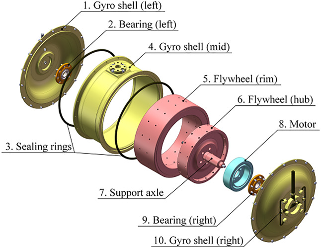
Inner structure of Gyroscope unit
Equation of floater motion
In general, the motions of floater induced by wave excitation involves six degrees of freedom (DOF). However, the floater motion of three translation DOFs cannot affectively generate gyro precession, and the gyro precession exhibits insensitivity in roll and yaw motion DOF of the floater motion. Therefore, we mainly investigate the motion effect in pitch DOF of the floater, which have been validated by reference48,49. and that have been verified in section of “Hydrodynamic analysis of the floater” later.
In this paper, some assumptions are given, that the fluid is both incompressible and inviscid, and the fluid motion exhibits small-amplitude irrotational behavior. Linear wave theory could model the irregular wave surfaces by superposing of numerous harmonic waves, with a specific energy distribution at different frequency. These waves could be represented by a collection time-domain motion of various water particle as
 |
1 |
where an, ωn and ψn are the amplitude, angular frequency and phase of the n-th harmonic wave, respectively. While, for the irregular waves, the energy of these harmonic wave components can be discretized with interval Δω as
 |
2 |
in which the spectral function S(ω) is determined by a double-parameters spectrum with the significant wave height ζs and peak period Tp (or peak frequency ωp), developed by the Joint North Sea Wave Project (JONSWAP). And the spectrum function is given by
 |
3 |
where ε is the factor of wave form defined as
 |
4 |
Thus, these theoretical models of a sequence of irregular waves could be used to examine the effects of wave excitation on floater. Once the wave surface function is derived, potential flow method is typically used to calculate the wave forces on floating body, as detailed in reference40. Additionally, the application of computational fluid dynamics (CFD) could expediently address this problem efficiently.
In the framework of linear wave theory, the time-domain motion equation of the floater can be formulated as
 |
5 |
where δ is the motion angle of floater, If and I∞ denote the inherent and added inertia of the floater, respectively; The second term is the function of radiation force caused by floater oscillation; The third term represents the hydrostatic restoring force with the stiffness coefficient κ; Texc expresses the torque caused by wave excitation; and Trea expresses the reaction torque from the gyroscopic.
The radiation force function in Eq. (1) incorporates a convolution term, which complicates the time-domain model calculation. To tackle this issue, reference49 replaced the convolution term with frequency-domain identification. Base on the linear assumptions, an approximation of convolution term is expressed by an equivalent state-space model as
 |
6 |
where
 |
7 |
 |
8 |
 |
9 |
and ξ = [ξ1, ξ2, ξ3, …, ξn]T represents the state vector with n states for the approximation of the wave radiation convolution term. Arad, Brad and Crad represent the coefficient matrices of state space model. Here, the coefficients ai, b1 and ci (i = 1, 2, …, n) can be referenced from reference49.
Gyroscope model
To study the dynamics of the gyroscope system, the specific coordinate systems are employed, as shown in Fig. 3. The coordinate systems include the inertial reference frame (O-XYZ), the floater reference frame (O-x1y1z1), and the gyro shell reference frame (O-x2y2z2). In the absence of external forces, these reference frames align with each other. Assuming that the gyro flywheel spins with a constant speed υ around Oz2, when sea wave propagates along the positive Z-axis direction, the motion of WEC takes place within the YOZ plane. The floater experiences wave forces and rotates by an angle δ along OX axis, then the shell will also produce an angular displacement θ around Oy1 axis due to the precession effect of the gyroscope. To bring these angular vectors into a reference frame, a transformation of angular velocity ω can be represented as follows
 |
10 |
 |
11 |
Fig. 3.

Gyroscope reference frame definition
where ωgyro and ωshell is angular velocity vector of the shell and gyro flywheel in the floater reference frame (O-x1y1z1), respectively. Ctr is the transformation matrix defined by
 |
12 |
Coriolis theorem asserts that when analyzing a vector within a rotating coordinate system, its absolute variation rate is equivalent to the sum of the relative variation rate in a moving coordinate system and the cross product of the angular velocity of the coordinate system and the vector itself. Consequently, combining the equation of angular momentum, it is possible to derive the dynamic equation for an individual gyroscope flywheel as follows.
 |
13 |
where Tgyro is torque vector of gyroscope flywheel, the angular momentum Hgyro of gyro flywheel is given by
 |
14 |
and its inertial matrix Jg is defined as
 |
15 |
When employing an approximation Igt ≈ Igs = Ig, the Eq. (13) can be expanded as
 |
16 |
where Tgx, Tgy and Tgz correspond to the components of Tgyro along the Ox, Oy and Oz axes, respectively. Tgx acts perpendicularly to the flywheel spinning direction, exerting an indirect force on the float to counteract its motion. Tgy provides the precession torque, which is balanced by the hydraulic PTO. Tgz refers to the axial component, and it will be balanced by the resistance and friction of the medium during flywheel rotation. Hence, the torque provided by the gyroscope to the PTO can be regarded as
 |
17 |
The current research has considered that the output torque of PTO system Tptois assumed as linear15,16. However, it hardly describes the intricate state of the novel inertial gyro and hydraulic PTO system with strong non-linear factors. The model of the dynamics about hydraulic PTO unit coupling with gyroscope precession would be established in the next section, to clarify how the inertial WEC is used to drive the hydraulic PTO unit.
Referring to the coordinate transformation in Fig. 3, the reaction torque exerted by the gyroscope on the float can be derived by
 |
18 |
Then an augmented state variable vector will be utilized to construct the new system state-space Eq.
 |
19 |
While the state-space model representation of the wave energy transfer to gyroscope can be expressed as
 |
20 |
where the coefficient matrices of the wave to gyroscope state-space model are denoted by
 |
21 |
 |
22 |
Hydraulic PTO model
The hydraulic PTO system is used to rectify and smooth the energy fluctuation from inertial WEC device, to maintain the hydraulic motor - generator unit running at its nominal state. Additionally, the hydraulic PTO minimizes the impact of energy fluctuations on electrical and mechanical components, and ensures the safe operation of the system. We have designed a hydraulic PTO unit with the hydraulic cylinder pumping mechanism as shown in Fig. 4, the hydraulic piston driving rods are linked to the ends of a crankshaft. This crankshaft is propelled by the precession shaft of gyroscope, where the precession torque generated by the gyroscope is utilized to actuate the hydraulic pistons back-and-forth oscillating motion, and to output hydraulic power.
Fig. 4.

Schematic diagram of pumping mechanism
The relationship between the hydraulic piston displacements xa, xb and the gyro precession angle θ can be expressed by follows,
 |
23 |
where rc is the radius length of the crankshaft.
Figure 5 shows that the rodless chamber of pump cylinder A is connected to the rod chamber of pump cylinder B, which is defined as Chamber 1, with an assumed uniform internal pressure of p1. Conversely, the rod chamber of pump cylinder A is connected to the rodless chamber of pump cylinder B, defined as Chamber 2, with an internal pressure of p2. Therefore, the forces experienced by the two pistons fa and fb can be represented as
 |
24 |
Fig. 5.

Connection of Hydraulic Cylinder Chambers
where Ap is the action area of the rodless chamber of cylinder; and σ is the ratio of the effective piston area between the rod chamber and rodless chamber.
Figure 6 depicts the system composition and principle of the hydraulic PTO unit. The gyroscopic precession drives the hydraulic cylinder pump to output pressure oil into the hydraulic circuit. A rectifier unit consists of four check valves, which are employed to manage the direction of hydraulic oil flow. When piston A compressing inward and piston B pulling outward, high-pressure hydraulic oil flows into the circuit through check valve 2, while low-pressure hydraulic oil is drawn into the pump cylinder through check valve 3. Consequently, the flow rate in the two chambers of the hydraulic pump cylinder can be expressed as
 |
25 |
Fig. 6.

Structural diagram of Hydraulic PTO system
where q1, q2, q3 and q4 correspond to the flow rate through check valve 1, 2, 3 and 4, respectively.
Subsequently, the flow rates and pressures of the high-pressure accumulator and low-pressure accumulators have their respective relationships, as
 |
26 |
where pH, pL are the pressure inside high-pressure and low-pressure accumulators, respectively; and VH, VL are the volume of high-pressure and low-pressure accumulators, respectively; qH, qL donates the flowrate through the accumulators. Commonly, the accumulator operation is assumed as adiabatic, meaning that the adiabatic index γ = 1.4.
Before entering the hydraulic motor, hydraulic oil flows through a throttle valve, the relationship between the valve orifice opening and the flow rate qm can be described as
 |
27 |
where Cd is the flow coefficient, Av is the valve orifice area, ρo is the density of fluid, and pm is the pressure acting on the hydraulic motor.
The hydraulic system ultimately generates electricity by a hydraulic motor driving a generator. Therefore, the dynamic equation of the hydraulic motor-generator load is
 |
28 |
where,Tgen represents the electrical load of the generator, which is considered to be resistive and is treated as a constant in this study. And the flow rate through the hydraulic motor can be expressed as
 |
29 |
where Jg and Bg represent the inertia and damping of the hydraulic motor-generator unit, respectively. Dm is the displacement of the hydraulic motor, and ωm is the rotation speed of the hydraulic motor.
The dynamics models of wave energy transferred by the inertial WEC coupling with the hydraulic PTO are formed by combining with above equations.
Adaptive hierarchical MPC strategy
The MPC method uses the hierarchical concept, which can solve a model-based unconstrained optimization problems offline by means of the prediction information of waves; then the online constraint handling can be performed based on real-time data feedback. Consequently, the burden of online computations is alleviated, and the real-time control effectiveness and precision are guaranteed.
Control model establishment
According to the mathematic models established in Sect. 2, we could combine these to create a comprehensive model that encompasses the entire process from wave energy to generator power output. Taking into account the nonlinear factors in these models, such as the gyroscope precession effect, hydraulic valves, and accumulators, we made an effort to linearize these factors locally starting from the zero position with θ = 0 in Eq. (17).
The volume and pressure of the high-pressure accumulator can be approximated as VH0 and pH0 at the initial state, then Eq. (26) can be linearized as
 |
30 |
where
 |
31 |
And the flow Eq. (27) of the hydraulic valve is linearized at zero position (xv0, pH0). Assuming that the valve orifice area Av is proportional to the valve spool displacement xv, then the linearized function is expressed by
 |
32 |
where kq0 and kc0 denote the flowrate coefficient and differential pressure of valve spool, respectively, which is given by
 |
33 |
 |
34 |
It is worth noting that the linearization assumptions in Eqs. (31) and (32) are valid only at the zero position. In the following subsection, a method of “Adaptive Gain Scheduling” is introduced, which is a concept of local linearization. Within a single wave period, multiple linearization positions can be selected for expanding to achieve global linearization.
These coefficients that can be affected by friction, leakage and pressure pulse in the fluid flowing process may cause power losses. To prevent pressure from exceeding the safety range in the hydraulic circuit, the valve orifice cannot be completely closed, so that the initial value xv0 is assigned as a constant, and the control input is determined by
 |
35 |
where kv0 denotes the displacement coefficient of valve spool, u denotes the control input of valve spool, respectively.
Based on the models established in Sect. 2, the state variable of inertial WEC and hydraulic TPO control system is redefined as follows
 |
36 |
A comprehensive state space representation of the control-oriented model of the inertial WEC and hydraulic TPO is expressed as
 |
37 |
where w is the input of wave acting on floater, the coefficient matrices Ac, Bc and Dc are respectively composed by
 |
38 |
 |
39 |
 |
40 |
in which.

In order to design the MPC controller, the continuous time model of the inertial WEC and hydraulic PTO is discretized using a Zero-Order Holder (ZOH) with the sampling time ts, so that the discrete model corresponding to Eq. (37) is obtained by
 |
41 |
where A, B and D respectively represent the discrete-time state space coefficient matrices.
An Np-step wave prediction sequence at instant step k of the wave energy input wk is given by
 |
42 |
The primary control aim of the inertial WEC and hydraulic PTO system is to maintain the running at constant speed of the hydraulic motor-generator unit, which means the output value error from the desired value is minimized. Hence the desired state is defined as xd, which is designed as a constant value in this paper. Thus, an augmented form of state space vector is given by
 |
43 |
An augment state space function is expressed by
 |
44 |
where Aa, Ba and Da respectively represent the discrete-time state space coefficient matrices of the inertial WEC and hydraulic PTO system.
The error vector ea is defined by
 |
45 |
where
 |
46 |
Based on the economic and safe concerns, constraints on the state and control inputs are incorporated into the control of the inertial WEC and hydraulic PTO. Constraints are applied to the input u to ensure that it does not exceed the maximum allowable valve orifice umax. The system variable pitch angle of the floater d is constrained to remain within dmax to ensure the safety of the pitch motion of floater. Additionally, constraints are imposed to the gyro precession q; if the precession angle exceed qmax, it may cause the piston displacement of hydraulic cylinder surpassing its permissible stroke range, which could potentially damage the hydraulic components. Hence the constrained optimal control problem of the inertial WEC and hydraulic PTO can be resolved as follows
 |
47 |
In Eq. (47), the terminal cost FNp is defined as
 |
48 |
The stage cost function of each k + i step is defined as L(k + i|k), which is expressed by
 |
49 |
where P0, S0 are the final coefficients, and the augment matrices Qa and R are the weight of state variable and input leading to convex quadratic programming (QP), respectively.
AHMPC controller design
The optimal control problem in Eq. (47) can be solved by dividing it into an offline unconstrained QP problem and an online real-time constraint handling problem. At each step k with given w(k), the objective of unconstrained optimal control is to minimize the value of cost function within the prediction horizon Np, and to compute the solution µ(k) that satisfies the control requirement. Then the unconstrained optimization formulation is
 |
50 |
Bellman principle states that the solution to an optimal problem can be obtained recursively by solving the sub-problems. By iteratively solving these sub-problems and updating the optimal cost function, which represents the maximum expected value at each state, then the overall optimal solution can be achieved. The optimal cost function at step k + i can be always represented as the sum of the stage cost and optimal cost function at k + i + 1. Moreover, it is believed that this function follows a quadratic programming form as follows
 |
51 |
where F*(k + i|k) represents the optimal cost function at step k + i.
In order to compute the control law, Eq. (51) should be satisfied the following relationship,
 |
52 |
Furthermore, to guarantee the Eq. (51) attaining the minimum value at µ(k + i|k), it is simultaneously necessary to meet the follows expression
 |
53 |
Thus, the control law of unconstrained optimal problem can be solved as the following expression
 |
54 |
where Kx|i is the feedback gain Kw|i is the gain coefficient of the wave prediction sequence.
 |
55 |
 |
56 |
 |
57 |
where
 |
58 |
 |
59 |
with
 |
60 |
The control law sequence within the horizon Np can be arranged by the expression based on the initial state xa(k|k) at instant time k. To simplify the expression, we substitute xa(k|k) with xk, then the state vectors within an entire predicted horizon are arranged by
 |
61 |
where the coefficient matrices are given as follows
 |
62 |
 |
63 |
 |
64 |
 |
65 |
with
 |
66 |
 |
67 |
 |
68 |
 |
69 |
So far, we have presented a comprehensive solution process offline for the control law of the unconstrained optimal problem, in which the coefficients Kx|i and Kw|i can be calculated offline based on wave force prediction wk.
In order to handle the explicit constraint problems, we contemplate to bring an additional optimization variable νk in control law that can be determined online. νk is only active when there is a violation of physical constraints, and its calculation as follows
 |
70 |
where µ(k + i|k) is consistent with the computation results offline.
In contrast to offline computation, online constraints handling involves a considerably shorter step horizon Nc, thereby greatly reducing the complexity of real-time calculations. The online solution is formulated by expression organized with in the horizon length as
 |
71 |
in which
 |
72 |
where gx|min, gx|max, gu|min, gu|max denote the boundary constraints on uk and Xk, respectively. And control law at the instant time k, is extracted from the first value of the vector uk.
 |
73 |
 |
74 |
Adaptive gain scheduling
The MPC control law has been designed based on a linear time invariant system, which is derived by approximating the model through linearization at the zero point. However, as the precession motion deviates from the zero position, the effectiveness of this linear system diminishes gradually. Since the system dynamic is quite slow, the gain coefficients in the computed control law can be scheduled as functions of the instant precession angle θ. The system is linearized at specific positions to calculate the feedback and feedforward gains for each point.
In order to compute the gains for a given state within the prediction horizon from step k to k + np, the approximate values of the nonlinear factors in the state coefficient matrix Ac, Bc and Dc at different positions can be chosen in an adaptive manner to match the precession angle θ, as depicted in Fig. 7. The calculation of control law remains consistent with the approach described above section.
Fig. 7.

Gyroscope at different position for gain scheduling
In order to facilitate a smooth transition of gain value between adjacent approximate points, a linear interpolation method can be used, as follows
 |
75 |
 |
76 |
where θmea is the instantaneous measurement value of the precession angle, and θj and θj+1 represent the boundary points of the discrete range, respectively.
Based on the control model and controller design law of the inertial WEC and hydraulic PTO system above, the procedural steps of the AHMPC algorithm is presented as shown in Fig. 8, along with a summary of its implementation.
Fig. 8.

Flowchart of AHMPC algorithm
Numerical simulation and analysis
Simulation model construction
In this section, a dynamic model was established using MATLAB/Simulink software based on the mathematical relationships discussed in Sect. 2, to provide an integrated environment for modeling, simulating and analyzing the dynamic characteristics of system. Figure 9 shows the energy conversion process from wave energy to electric energy, as well as the dynamic relationships between different subsystems. The simulation construction of the entire inertial WEC and hydraulic PTO system is established based on this depiction.
Fig. 9.

Wave energy conversion process
The simulation purpose is to investigate the influence of the major variables of individual unit on the overall system performance. The physical parameters of the WEC floater and gyroscope, which align with the design values of the real experimental platform, are presented in Table 1. For numerical simulation, a set of wave sequences, with different peak periods, which coming from the wave spectrum developed by JONSWAP, is employed as the wave-induced force acting on the WEC device.
Table 1.
Physical parameters of the WEC floater and gyroscope.
| Quantity | Units | Value | |
|---|---|---|---|
| Floater | Length | m | 1.60 |
| Width | m | 1.02 | |
| Draught | m | 0.587 | |
| Mass | kg | 682 | |
| Inertial radius of pitch | m | 0.458 | |
|
Center of gravity (from water surface) |
m | 0.204 | |
| Gyroscope | Flywheel radius | m | 0.152 |
| Flywheel mass | kg | 29.8 | |
| Inertia of flywheel | kg·m2 | 0.211 |
In this section, the Simscape/Multibody toolbox is used to establish a mechanical simulation model of gyroscope unit, as depicted in Fig. 10. The main components include the floater, the gyroscope shell and flywheel. The model takes the wave excitation pitching torque as its input and generates the gyro precession torque as its output.
Fig. 10.

Gyroscope model developed in MATLAB/Simulink
The hydraulic PTO model is constructed using Simscape/Fluids, as shown in Fig. 11, and the components consist of pump module, rectifying valves, power regulation and output modules. In the low-pressure circuit, a tank is set the pressure as one standard atmosphere.
Fig. 11.

Hydraulic PTO model developed in MATLAB/Simulink
In the follow subsections, the major variables of the gyroscope and hydraulic PTO unit are separately studied to evaluate their impact on the entire system, which serves as a basis for selecting actuators and designing controller for the subsequent control implementation.
Hydrodynamic analysis of the floater
The hydrodynamic parameters in the frequency domain could be computed using commercial program ANSYS AQWA, and the hydrodynamic parameters of the floating body, including additional inertia and radiation damping, were obtained, as shown in Fig. 12.
Fig. 12.

Calculation results of (a) Added inertial and (b) Radiation damping of floating body
The simulation results from AQWA show that the amplitude of rolling and yawing motion is much lower than that of pitching motion of the floating body, when the low-frequency wave incidence direction is in the positive direction of Ozf axis. Therefore, in this section, the motion of floating body is only represented by the pitch motion.
According to the frequency domain regression method mentioned above, the linear approximation system of the convolution term is obtained by identifying the original radiant force, and the state space coefficient of the linear system can be solved. The identification results of delay function h(w) in the pitch mode are highly consistent with the original system, as shown in Fig. 13. Therefore, the results can be used to approximate the radiant force of the floating body in the time domain.
Fig. 13.

Identification result of (a) amplitude and (b) phase of delay function h(w)
The time delay function in the pitch direction is identified to obtain a linear approximate system of 7-order, whose state-space coefficient matrix is as follows:

All poles of the linear system are located in the left half of the complex plane s, which ensures the stability of the system. The comparison of the calculated results of the RAO (response amplitude operator) of the WEC floating body in the frequency domain and the time domain are shown in Fig. 14. It can be seen that the time domain calculation results of the identified state space have a good agreement with the frequency domain calculation results, which verifies the validity of the system identification results. The model can be used to investigate the dynamic interaction between an inertial gyro system and a floating body.
Fig. 14.

Comparison of RAO calculation results in time domain and frequency domain of floating body pitching
Influence analysis of the gyroscope
The wave energy absorption capacity of WEC is significantly influenced by the gyroscope angular momentum that is mainly contributed by the spin speed of the gyro flywheel. In the simulation process, a certain hydraulic-load is acted on system, while only the rotation speed of the flywheel is varied, the simulation results of the output power are shown in Fig. 15, which depicts the variation of instantaneous output power with different flywheel spin speeds as 5000 r/min, 6000 r/min and 7000 r/min, respectively. It can be seen that the inherent sinusoidal-like fluctuations of the waves are significantly weakened to remain a minor oscillation, this result is due to hydraulic transmission system as pulsation dampener. It is noteworthy that the output power occurs at 6000 r/min exceeding the values at 5000 r/min or 7000 r/min, which suggests a non-monotonic impact of flywheel speed on energy absorption, so that an optimal speed of the gyro flywheel should be existing.
Fig. 15.

Instantaneous output power changing with flywheel speed
In order to elucidate this phenomenon, sampling within the range from 4000 to 10,000 r/min, the time-average output powers are investigated respectively under wave peak period Ts of 3s, 4s and 5s. The results are shown in Fig. 16.
Fig. 16.

Average output power changing with flywheel speed
Figure 16 shows that the average output power increase with the wave peak period decreasing. In Fig. 16, it can be also observed that the average output power of system initially increases and then decreases with flywheel spin speed increasing. This indicates that for a specific wave state, there exists an optimal flywheel spin speed υ at which the wave power absorption is maximum. This phenomenon can be explained by the Eq. (17) and Eq. (18). An increasing υ intensifies the precession effect of the gyro flywheel, at the same time, the angular momentum increasing exhibits more pronounced axial stability, and suppresses the pitch oscillation of the floater. When the flywheel spinning speed continues to increase, the influence of reactive torque becomes dominant, and leads to the output power gradual to decrease. These competing factors result in an optimal υ at which the corresponding absorption power reaches its peak.
The parameters of the gyroscope have some effects on the wave energy absorption capacity, but they are not exclusive determining factors. The variations of hydraulic system parameters also effect on the gyro flywheel power system.
Influence analysis of the hydraulic system
The hydraulic energy conversion system can serve as actuating elements in the system control process. The physical and operating parameters of the hydraulic system are presented in Table 2. The hydraulic accumulator, flow valve, and hydraulic motor-generator unit are primary elements that are employed to regulate and to control the pressure and flowrate in the hydraulic circuit. When the gyro flywheel speed is set to 8000 r/min, the simulation results provide a clear demonstration on the system adjustability.
Table 2.
Physical parameters of the hydraulic system.
| Quantity | Units | Value |
|---|---|---|
| Rodless chamber area (Ap) | m2 | 0.00049 |
| Ratio of the piston area (σ) | — | 0.4 |
| Torque of load (Tl) | N·m | 0.1 |
| Crank length (2rc) | m | 0.2 |
| Inertia of generator (Jg) | kg·m2 | 0.005 |
| Damping of generator (Bg) | N·m/rad/s | 0.012 |
Accumulator plays an important role in absorbing energy fluctuations in the hydraulic circuit. It stores pressure energy during the higher pressure than mean value period and releases it at lower pressure than mean value, thereby protects the hydraulic elements from the pressure impact. The capacity of accumulator to absorb energy pulsations is determined by its volume and pre-charge pressure, which directly influence the energy transfer capability and effect of hydraulic PTO system.
Figure 17 depicts the influence of accumulator initial volume VH0 and pre-charge pressure pH0 on the average output power of the hydraulic motor-generator unit with different wave states. In this case, Av is set to 1.2 × 10⁻⁶m2, Dm is set to 1.5 × 10⁻⁶ m3/r, and the wave peak period is 3s, 4s and 5s, respectively. Figure 17(a) depicts the average output power with different volume VH0 with a defined pH0 at 1.0 MPa, and Fig. 17(b) shows the average output power changing with various pre-charge pressure pH0 with VH0 set as 1.0 L. The simulation results show that the average output power increases with the wave peak period decreasing, but does not change with VH0 or pH0 changing. Therefore, it can be concluded that within the exploration range, the average output power remains constant with variations in the parameters VH0 or pH0. However, these parameters only affect the amplitude of the fluctuations of the power, serving to change the damping capacity of the hydraulic system.
Fig. 17.

Variation of average output power with (a) accumulator initial volume VH0 and (b) pre-charge pressure pH0
Figure 18 shows the influence of accumulator initial volume VH0 and pre-charge pressure pH0 on the fluctuation of output power with different wave periods. The simulation results show that the fluctuation of output power decreases with the wave peak period decreasing. While in Fig. 18(a), the fluctuation of output power in the hydraulic circuit decreases when the accumulator initial volumes increasing, and clearly demonstrating that larger volumes result in smaller output power pulsations. This implies that a larger-sized accumulator can absorb energy fluctuations more efficiently. In Fig. 18(b), the fluctuation of output power grows monotonically with pre-charge pressure increasing. However, in simulations, it was found that in the hydraulic system with either large initial volume or small pre-charge pressure, the accumulator requires a longer time to achieve a stable state when facing the external environment changing. In such cases, real-time responsiveness becomes challenging. So that it is crucial to determine the appropriate parameters of the accumulator.
Fig. 18.

Output power fluctuation with (a) accumulator initial volume VH0 and (b) pre-charge pressure pH0
Flow valve controls the flowrate of hydraulic circuit by adjusting the valve orifice area, thereby regulates the output speed of the hydraulic motor. Figure 19 shows the variations in average output power with respect to the valve orifice area under different wave states with period of 3s, 4s and 5s, respectively, when Dm is assigned a value of 1.5 × 10⁻⁶ m3/r. To prevent the hydraulic pressure from exceeding the safety threshold, it is necessary to avoid completely closing the valve orifice. Therefore, the minimum valve orifice area is set to 0.4 × 10⁻⁶m2. The simulation results indicate that the average output power rapidly increases as the valve orifice area Av increases from the minimum value to 1.0 × 10⁻⁶m2. Once a specific threshold is reached, the rate of change becomes more gradual, ultimately leading to a stationary state. This result suggests that the average output power is extremely responsive to variations in the smaller valve orifice area, and this adjustability is constrained within a specific range. When surpassing this range, the power regulating ability significantly diminishes.
Fig. 19.

Average output power changing with valve orifice area
The displacement of the hydraulic motor is another crucial factor that requires to be thoroughly analyzed. It directly determines the transmission performance of the hydraulic system, then affects the output capacity of the hydraulic motor. Figure 20 presents the variations in average output power with respect to hydraulic motor displacement Dm under different wave states with period of 3s, 4s and 5s, respectively, when Av is designated as 1.2 × 10⁻⁶m2. It can be observed that the output power decrease with Dm increasing, and the rate of descent is relatively consistent. When designing the hydraulic motor-generator unit, it is necessary to consider compatibility both the hydraulic motor Dm and rated speed of the generator. This imposes a limitation on the hydraulic motor displacement within a specific range, in order to ensure the stable and secure operation on the hydraulic motor-generator unit.
Fig. 20.

Average output power changing with motor displacement
In this section, the simulation results are summarized as follows. First, the average output power of the inertial WEC and hydraulic PTO system increases with the wave peak period decreasing within a specified range, it is important to adapt the WEC system operation to the different wave states. Second, the adjustment of the gyro flywheel speed has a peak effect on the average output power of the system, which requires the identification of an optimal speed to maximize power generation. Third, in the hydraulic system, the volume of accumulator has minimal impact on the average output power of the hydraulic motor-generator unit at steady state, but plays a critical role in managing energy fluctuations. Then, both the valve orifice area Av and the hydraulic motor displacement Dm can regulate the output power of the inertial WEC and hydraulic PTO system, with different characteristic curves of variation. The former allows for small valve orifice sensitive control but with lower precision, while the latter enables nearly proportional control but within limited adjustment range. Therefore, the selection of control method should be determined based on specific scenarios and control objectives.
Analysis of power loss
Analyzing the power loss of WEC is an important work. In this paper, the power loss of the WEC mainly occurs in two parts: the rotating gyroscopic flywheel and the hydraulic PTO circuit. Due to the vacuum treatment inside the gyroscope, with the vacuum level is around 10 Pa, the power loss caused by air resistance is limited to below 1 W. At this point, the mechanical losses caused by the bearing friction in the inertial gyroscope play a dominant role in power losses. There are many factors that affect the friction losses between the flywheel and the bearings, including the coefficient of friction, normal force, flywheel rotational speed, and lubrication conditions. Friction losses can lead to a reduction in the overall efficiency of the system, causing energy to be converted into heat, which may subsequently lead to an increase in the temperature of the bearings and flywheel, affecting the performance and lifespan of the materials. Based on the parameters of the gyroscope in Table 1, In the case of well-lubricated (rolling friction coefficient (µ ≤ 0.001), the power loss during the rotation of the flywheel is illustrated in the Fig. 21. It can be seen that the power loss has a linear relationship with the gyro rotational speed, and its impact becomes more significant at higher speeds. The ratio of the power loss in the output power can approximately reach 7%.
Fig. 21.

Mechanical power loss changing with gyro flywheel speed
The power losses in hydraulic PTO systems are a complex phenomenon that can occur anywhere within the hydraulic circuit, including hydraulic cylinders, hydraulic motors, pipes, and valves. It is typically caused by leakage in hydraulic components or friction in the hydraulic fluid. The power losses models for each hydraulic component are referenced from the reference50. In this section, we present the power losses generated by several major hydraulic components during operation under different wave periods, as shown in Fig. 22.
Fig. 22.

Power losses in the hydraulic circuit
From Fig. 22, it can be seen that the power loss generated by the hydraulic motor is the most prominent, accounting for about 16% of the total power losses, which is caused by the leakage in the hydraulic motor. Then the power loss at the throttle valve is the second most significant, accounting for about 7% of the total power losses, which is due to the pressure drop across the throttle valve. The remaining power loss is approximately 4%, primarily consisting of pressure drops in the check valves, hydraulic cylinder, piping, and fluid friction.
Implementation and validation of AHMPC controller
In this section, the AHMPC controller mentioned above is applied to inertial WEC device, to verify its effectiveness. The simulation parameters of the system are determined as list in the Tables 1 and 2. The flywheel speed υ is set as 6000 r/min, the volume of accumulator Vh is selected as 1.6 L and the displacement of hydraulic motor Dm is assigned as 1.5 × 10⁻⁶ m3/r. Considering the operation safety of the equipment, the constraints on pitch angle δ of the floater and the precession angle θ of the gyroscope are defined as follows.
 |
77 |
A wave sequence with a significant wave height ζs = 0.5 m and a peak period Ts =3 s, based on the JONSWAP spectrum, is utilized in the simulation to act as the excitation on the WEC device. And the wave prediction length is set as 10 s with a discrete time intervals ts=0.1 s, with a Np-step of horizon length is 100, and an online Nc-step of horizon length is 10. The running time range from 800 s to 1000 s. Initially, the purposed AHMPC controller could match the desired control requirements of the hydraulic system was validated. The control goal is to regulate and maintain the rotational velocity of the hydraulic motor at a predefined speed value. Figure 23 shows two conditions: the time varying of the hydraulic motor rotation speed without the controller activated and with the controller engaged. The desired speed is set as 300 r/min, and their corresponding curves in the steady state is given in Fig. 23(a) and (b), respectively.
Fig. 23.

Motor speed changing under condition (a) without controller and (b) with AHMPC controller
Figure 24 shows the behavior of some other variables in the simulation results related to the proposed control. Figure 24(a) shows the precession behavior of the gyro system, and Fig. 24(b) represents the pressure variations in the hydraulic circuit. In this figure, p1 and p2 denote the pressures in the two chambers of the hydraulic pump given in Fig. 6, and these pressures represents the total pressure pH the hydraulic circuit.
Fig. 24.

(a) Precession angle of Gyro and (b) Pressure in hydraulic circuit
Previous numerical simulations in Sect. 3 have already demonstrated the fluctuations absorption capability of hydraulic system from the wave energy transmission process. Due to the inherent irregular and randomness of ocean waves, the energy transmitted in the hydraulic circuit still experiences localized fluctuations. During the time range depicted in Fig. 24, the motor speed fluctuated as much as 13.18 r/min without the introduction of control. However, when the controller is activating, this variation is significantly reduced to 0.52 r/min, and marking 96% decrease in fluctuation. In order to quantify these differences, the root mean squared error (RMSE) is used as evaluation index for tracking, as defined by
 |
78 |
where N is the total number of steps, ωi corresponds to the speed of the hydraulic motor-generator at each step, and ωd is the desired speed, set as 500 r/min in the simulation. The implementation of the MPC controller offers additional mitigation of energy fluctuations. Figure 23 (a) shows that, in the absence of control, the value of RMSE measures 2.7302 × 10⁻². While, with the adoption of purposed AHMPC in Fig. 23 (b), RMSE reduces to 9.8944 × 10⁻⁴, representing a significant decrease in error. This result shows the robust tracking performance of the AHMPC controller, further smoothing the energy fluctuation in the hydraulic system.
Speed control is related to the control and regulation of the flow uniformity into the motor. AHMPC strategy can have a good real-time control ability on the hydraulic circuit flow control valve, ensure the flow balance of the hydraulic motor, and thus improve the running stability of the hydraulic motor driven engine. Furthermore, research about the instant output power of the hydraulic motor is shown in Fig. 25. It is evident that the controller smoothens the hydraulic power well, thereby improving the safety and reliability of the motor and generator unit. In this study, it is assumed that the electrical load of the generator is constant, allowing the output power of the generator to be expressed accordingly as
 |
79 |
Fig. 25.

Instant output power of the hydraulic motor
It can be observed that the power output of the generator is proportional to its speed. Therefore, in a system where the load is defined, maintaining a constant speed of the hydraulic motor ensures the stability of the output power of the generator. The curves in Fig. 25 shows that the output power of hydraulic motor have the similarly behaviors following those of the motor speed in Fig. 23, provided that the driving load on the hydraulic motor is known. It means that the output power could be adjusted and controlled indirectly.
Additional studies were carried out to assess the fluctuations in the hydraulic motor speed with various wave excitations, under the control regime, as depicted in Fig. 26. The mean power of waves is introduced, denoted as Pw, which is a function related to the significant wave height ζs and peak period Tp, referenced by reference12.
 |
80 |
Fig. 26.

RMSE of motor speed changing with various mean wave power
In Fig. 26, The RMSE value of the hydraulic motor speed increases as the wave mean power escalates under controlled, which show a decline on the control accuracy with the severe wave conditions, the RMSE value is also corresponding raising with the desired speed increasing. The analysis indicates that increasing the mean power can enhance the load characteristics of the hydraulic PTO system (such as equivalent damping). This results in pressure increase in the high-pressure side in the hydraulic circuit, and causing greater pressure drop across the valve. According to Eq. (32), the increase pressure drop acts as a disturbance that affects the control accuracy.
Then, a comparison on control effectiveness was conducted between the proposed AHMPC strategy and the conventional MPC method. Due to the presence of computation errors, both methods were independently run 10 times, and the average results were calculated. The Nc was set as 10, MATLAB 2019b was utilized to generate all simulation results on a computer system running Windows 11. The system specifications include an Intel® Core TM i7 CPU at 2.8 GHz and 16GB of memory. Tables 3 and 4 present the results with varying values of horizon length Np from 100 to 400, showcasing the RMSE values and computation time of both methods, respectively.
Table 3.
RMSE of AHMPC and conventional MPC (×10 − 3 r/min).
| Horizon length | AHMPC | Conventional MPC |
|---|---|---|
| 100 | 1.499 | 1.530 |
| 200 | 1.515 | 1.218 |
| 300 | 1.375 | 1.264 |
| 400 | 1.219 | 1.089 |
Table 4.
Computation time of AHMPC and conventional MPC (s).
| Horizon length | AHMPC | Conventional MPC |
|---|---|---|
| 100 | 1.643 | 2.197 |
| 200 | 2.791 | 5.382 |
| 300 | 3.256 | 8.658 |
| 400 | 3.587 | 11.643 |
The results in Table 3 shows that both methods exhibit a slight reduction in calculation errors with an increase in the field of view, but the difference between them is negligible. However, from Table 4, it can be seen that the conventional MPC method experiences a significant increase in computation time, whereas AHMPC shows only a gradually increasing. At Np = 400, the conventional MPC method takes three times as long to compute compared to AHMPC, and the gap will continue to grow with the horizon increasing. This demonstrates that the proposed AHMPC control method offers an improved real-time capacity in practical hydraulic motor-generator working environments, and substantially enhances the operational efficiency of the control method without compromising control accuracy.
Conclusions
In this paper, an inertial WEC and hydraulic PTO system is proposed, which utilizes a gyroscope device to absorb wave energy, coupled with a hydraulic circuit for energy rectification and transmission. The design of inertial WEC device is initially introduced, including the internal components and the structural of the gyroscope. Models from wave to floater to gyroscope are developed, and the convolution radiation force model is linearized using a state-space approach. Subsequently, the precession equation for the gyroscope is derived. Then a hydraulic cylinder pumping mechanism is designed, as well as the composition of the hydraulic circuit is illustrated. The principle of the hydraulic system accomplishes rectification and buffering is explained, to ensure the smooth operation of the hydraulic motor-generator unit. An AHMPC strategy is involved that addressed the offline unconstrained energy maximization control problem using a larger horizon of wave predicted sequences, then the online constraint is handled with a smaller horizon, ensuring the safety and efficiency of operation.
Numerical simulations have validated the feasibility of the inertial WEC and hydraulic PTO system, and the research was conducted on the influence of major components to system performance, such as gyro flywheel, hydraulic accumulators, flow valves, and hydraulic motors. The speed of flywheel has a non-monotonic effect on the output power of the system, with a peak value occurs at approximately 6000 r/min. Other parameters, such as the flow valve orifice and the displacement of hydraulic motor, affect the power in a consistent but non-proportional fashion. Moreover, the initial volume and pre-charge pressure of the accumulator has minimal effect on power magnitude, but plays a decisive role in power fluctuations during hydraulic circuit operation.
An AHMPC controller is designed, in conjunction with the hydraulic circuit control, which further reduces the energy fluctuations in the system, reducing amplitude variations by as much as 96%, and ensures the smooth output of the hydraulic motor-generator unit aligned with the desired aims. And a value of RMSE is introduced to quantify these differences. The output power of the hydraulic motor has also been greatly smoothed. Additionally, we studied the control performance under different mean wave power. Then a simulation demonstrated that AHMPC strategy improves the computation efficiency over conventional MPC, while maintaining the control precision.
However, this study has several limitations. One aspect is that the transmission efficiency of the hydraulic PTO system is not satisfactory enough. To address this, we propose implementing a closed-loop recycled hydraulic circuit, which could reduce hydraulic fluid leakage and enhance the efficiency of the hydraulic PTO system. Additionally, we aim to optimize the layout of the hydraulic system to make it more compact and efficient, thereby shortening the length of hydraulic lines and minimizing power losses due to hydraulic fluid friction. Another limitation is that the control effectiveness is determined by the linear system model. Therefore, it is essential to explore lower-order models that maintain the necessary accuracy for linearization, which will further reduce computational load and improve the real-time performance of the control system.
Acknowledgements
Not applicable.
Author contributions
Author Contributions: Conceptualization, Z.P. and Z.T.; methodology, H.J.; software, H.J.; validation, H.J. and M.L. and Z.T.; formal analysis, H.J.; investigation, H.J.; resources, H.J. and Z.T.; data curation, H.J. and M.L.; writing—original draft preparation, H.J.; writing—review and editing, H.J., Z.P. and Z.T.; visualization, H.J.; supervision, Z.P.; project administration, Z.P.; funding acquisition.
Funding
This research received no funding.
Data availability
The datasets used and/or analyzed during the current study are available from the corresponding author on reasonable request.
Declarations
Competing interests
The authors declare no competing interests.
Footnotes
Publisher’s note
Springer Nature remains neutral with regard to jurisdictional claims in published maps and institutional affiliations.
References
- 1.Gunn, K. & Stock-Williams, C. Quantifying the global wave power resource. J. Renew. Energy. 44, 296–304 (2012). [Google Scholar]
- 2.Liu, W. et al. Network Topology Optimization of Triboelectric Nanogeneratorsfor Effectively Harvesting Ocean Wave Energy. J. iScience. 23(12). (2020). [DOI] [PMC free article] [PubMed]
- 3.Das, T. K., Islam, N., Samad, A. & Pasha, A. A. Passive flow control via tip grooving and stall fencing mechanisms of a marine energy harvesting turbine. J. Scientific reports. 13(2677). (2023). [DOI] [PMC free article] [PubMed]
- 4.Contestabile, P., Crispino, G., Di Lauro, E. & Ferrante, V. Overtopping breakwater for wave energy conversion: review of state of art, recent advancements and what Lies ahead. J. Renew. Energy. 147, 705–718 (2020). [Google Scholar]
- 5.Sorek, S. & Sulisz, W. A serpent-type wave energy converter. J. Scientific reports. 13(12458). (2023). [DOI] [PMC free article] [PubMed]
- 6.Salter, S. H. Wave power. J. Nat.249, 720–724 (1974). [Google Scholar]
- 7.Salter, S. H. Power conversion systems for ducks. Proceeding of International Conference on Future Energy Concepts. London. (1979).
- 8.Stansby, P., Carpintero Moreno, E. & Stallard, T. Large capacity multi-float configurations for the wave energy converter M4 using a time-domain linear diffraction mode. J. Appl. Ocean. Res.68, 53–64 (2017). [Google Scholar]
- 9.Zheng, S., Zhang, Y. & Sheng, W. Maximum theoretical power absorption of connected floating bodies under motion constraints. J. Appl. Ocean. Res.58, 95–103 (2016). [Google Scholar]
- 10.Wu, J. et al. Optimizing the performance of solo Duck wave energy converter in tide. Energies J.3 (10), 289 (2017). [Google Scholar]
- 11.McCabe, A. P., Bradshaw, A., Meadowcroft, J. A. C. & Aggidis, G. Developments in the design of the PS frog Mk 5 wave energy converter. Renew. Energy J.31 (2), 141–151 (2006). [Google Scholar]
- 12.Josset, C., Babarit, A. & Clément, A. H. A wave-to-wire model of the SEAREV wave energy converter. J. J. Eng. Maritime Environ.221 (2), 81–93 (2015). [Google Scholar]
- 13.Crowley, S., Porter, R., Taunton, D. J. & Wilson, P. A. Modelling of the WITT wave energy converter. J. Renew. Energy. 115, 159–174 (2018). [Google Scholar]
- 14.Paduano, B. et al. Data-Based control synthesis and performance assessment for moored wave energy conversion systems: the PeWEC case. J. IEEE Trans. Sustainable Energy. 15 (1), 355–367 (2024). [Google Scholar]
- 15.Bracco, G., Giorcelli, E. & Mattiazzo, G. ISWEC: A gyroscope mechanism for wave power exploitation. J. Mechanism Mach. Theory. 46 (10), 1411–1424 (2011). [Google Scholar]
- 16.Khedkar, K., Nangia, N., Thirumalaisamy, R. & Bhalla, A. P. S. The inertial sea wave energy converter (ISWEC) technology: device-physics, multiphase modeling and simulations. J. Ocean. Energy. 229, 108879 (2021). [Google Scholar]
- 17.Bracco, G., Giorcelli, E. & Mattiazzo, G. Experimental validation of the ISWEC wave to PTO model. J. Ocean. Energy. 120, 40–51 (2016). [Google Scholar]
- 18.Bonfanti, M. & Sirigu, S. A. Spectral-domain modelling of a non-linear wave energy converter: analytical derivation and computational experiments. J. Mech. Syst. Signal. Process.198, 110398 (2023). [Google Scholar]
- 19.Sirigu, S. A. et al. Pitch Resonance Tuning Tanks: A Novel Technology for More Efficient Wave Energy Harvesting (C. OCEANS 2018 MTS/IEEE Charleston, SC, 2018). [Google Scholar]
- 20.Paduano, B. et al. Experimental and numerical investigation on the performance of a moored pitching wave energy conversion system. J. IEEE J. Ocean. Eng.49 (3), 802–820 (2024). [Google Scholar]
- 21.Mohd, A. J., Mohd, Z. I., Muhamad, Z. D., Aliashim, A. & Zulkifli, M. Y. Hydraulic power Take-Off concepts for wave energy conversion system: A review. J. Energies. 12, 4510 (2019). [Google Scholar]
- 22.Boake, C. B., Whittaker, T. J. T., Folley, M. & Ellen, H. Overview and initial operational experience of the LIMPET wave energy plant. J. Proc. Int. Offshore Polar Eng. Conf.12, 586–594 (2002). [Google Scholar]
- 23.Rusu, E. & Onea, F. A review of the technologies for wave energy extraction. J. Clean. Energy. 2, 10–19 (2018). [Google Scholar]
- 24.Igic, P. et al. Multi-megawatt offshore wave energy converters-electrical system configuration and generator control strategy. J. IET Renew. Power Generation. 5 (1), 10–17 (2011). [Google Scholar]
- 25.Sang, Y. et al. Energy extraction from a slider-crank wave energy converter under irregular wave conditions. J. OCEANS 2015 MTS/IEEE Wash. (Washington, DC, USA ). 10.23919/OCEANS.2015.7401873 (2015).
- 26.Gaspar, J. F., Calvário, M., Kamarlouei, M. & Guedes Soares, C. Power take-off concept for wave energy converters based on oil-hydraulic transformer units. J. Renew. Energy. 86, 1232–1246 (2016). [Google Scholar]
- 27.Liu, C., Yang, Q. & Bao, G. Influence of hydraulic power take-off unit parameters on power capture ability of a two-raft-type wave energy converter. J. Ocean. Energy. 150, 69–80 (2018). [Google Scholar]
- 28.Falcão, A. F. O. & Antonio, F. Modelling and control of oscillating-body wave energy converters with hydraulic power take-off and gas accumulator. J. Ocean. Eng.34 (14), 2021–2032 (2007). [Google Scholar]
- 29.Garcia-Rosa, P. B. et al. Wave-to-Wire model and energy storage analysis of an ocean wave energy hyperbaric converter. J. IEEE J. Ocean. Eng.39 (2), 386–397 (2014). [Google Scholar]
- 30.Tri, N. M. et al. A novel control method to maximize the energy-harvesting capability of an adjustable slope angle wave energy converter. J. Renew. Energy. 97, 518–531 (2016). [Google Scholar]
- 31.Costello, R., Ringwood, J. V. & Weber, J. Comparison of two alternative hydraulic PTO concepts for wave energy conversion. JIn Proceedings of the 9th European Wave and Tidal Energy Conference (EWTEC) (Southampton, UK), 5–9 (2011). [Google Scholar]
- 32.Zhang, D. H., Li, W., Zhao, H. T., Bao, J. W. & Lin, Y. G. Design of a hydraulic power take-off system for the wave energy device with an inverse pendulum. J. China Ocean. Eng.28 (2), 283–292 (2014). [Google Scholar]
- 33.Hansen, R. H. et al. Discrete displacement hydraulic power Take-Off system for the wavestar wave energy converter. J. Energies. 6 (8), 4001–4044 (2013). [Google Scholar]
- 34.Bonfanti, M. & Giorgi, G. Improving computational efficiency in WEC design: Spectral-Domain modelling in Techno-Economic optimization. J. J. Mar. Sci. Eng.10 (10), 1468 (2022). [Google Scholar]
- 35.Pei, Z., Jing, H. & Tang, Z. Modeling and test results of an innovative gyroscope wave energy converter. J. Appl. Sci.11 (10), 4359 (2021). [Google Scholar]
- 36.Anderlini, E., Forehand, D. I. M., Bannon, E. & Abusara, M. Control of a realistic wave energy converter model using Least-Squares policy iteration. J. IEEE Trans. Sustainable Energy. 8 (4), 1618–1628 (2017). [Google Scholar]
- 37.Vissio, G. et al. ISWEC linear quadratic regulator oscillating control. J. Renew. Energy. 103, 372–382 (2017). [Google Scholar]
- 38.Zhan, S., Li, G., Na, J. & He, W. Feedback noncausal model predictive control of wave energy converters. J. Control Eng. Pract.85, 110–120 (2019). [Google Scholar]
- 39.Zhan, S., Stansby, P., Liao, Z. & Li, G. A fast model predictive control framework for multi-float and multi-mode-motion wave energy converters. J. IEEE Trans. Control Syst. Technol.31 (3), 1443–1450 (2023). [Google Scholar]
- 40.Faedo, N., Scarciotti, G., Astolfi, A. & Ringwood, J. V. Nonlinear energy-Maximizing optimal control of wave energy systems: A Moment-Based approach. J. IEEE Trans. Control Syst. Technol.29 (6), 2533–2547 (2021). [Google Scholar]
- 41.Faedo, N., Olaya, S. & Ringwood, J. V. Optimal control, MPC and MPC-like algorithms for wave energy systems. J. IFAC J. Syst. Control. 1, 37–56 (2017). [Google Scholar]
- 42.Ringwood, J. V. Wave energy control: status and perspectives 2020. J. IFAC Papers Online. 53 (2), 12271–12282 (2020). [Google Scholar]
- 43.Bonfanti, M., Carapellese, F. & Sirigu, S. A. Excitation forces Estimation for Non-linear wave energy converters: A neural network approach. J. IFAC PapersOnLine. 53 (2), 12334–12339 (2020). [Google Scholar]
- 44.Bonfanti, M. & Sirigu, S. A. Real-time wave excitation forces estimation: an application on the ISWEC device. J. J. Mar. Sci. Eng.8 (10), 1–30 (2020). [Google Scholar]
- 45.Hillis, A. J., Brask, A. & Whitlam, C. Real-time wave excitation force Estimation for an experimental multi-DOF WEC. J. Ocean. Energy. 213, 107788 (2020). [Google Scholar]
- 46.Nguyen, H. & Tona, P. Wave excitation force Estimation for wave energy converters of the Point-Absorber type. J. IEEE Trans. Control Syst. Technol.26 (6), 2173–2181 (2018). [Google Scholar]
- 47.Liao, Z., Gai, N., Stansby, P. & Li, G. Linear Non-Causal optimal control of an attenuator type wave energy converter M4. J. IEEE Trans. Sustainable Energy. 11 (3), 1278–1286 (2020). [Google Scholar]
- 48.Jia, H., Pei, Z., Tang, Z. & Yang, J. Modeling and analysis of an inertia wave energy converter and its optimal design. J. J. Mar. Sci. Eng.11(7), 1351 (2023). [Google Scholar]
- 49.De Seixas, J. & Brizzolara, S. Mathematical framework for hydromechanical Time-Domain simulation of wave energy converters. J. Math. Probl. Eng. 1–15, 1710253. 10.1155/2018/1710253 (2018).
- 50.Liu, C. et al. A high-precise model for the hydraulic power take-off of a raft-type wave energy converter. J. Energy.215, 119107. 10.1016/j.energy.2020.119107 (2021).
Associated Data
This section collects any data citations, data availability statements, or supplementary materials included in this article.
Data Availability Statement
The datasets used and/or analyzed during the current study are available from the corresponding author on reasonable request.