

Abstract
This paper presents the use of a static synchronous compensators (STATCOM) device to improve the low voltage ride through (LVRT) ability of an electrical network consisting of wind farms that produce 9 MW and 1 MW PV stations during grid faults. A hybrid energy model is connected with 100 MVAR STATCOM at the point of common coupling (PCC) through line to line fault occurs on the grid. STATCOM control is used to detect the voltage at the PCC bus through occurring line to line (LL) faults by compensating reactive energy. A method of particle swarm optimization (PSO) is utilized for adjusting the optimum value of proportional—integral—derivative (PID) STATCOM control. STATCOM is controlled by (PID) and is compared with STATCOM controlled by fuzzy logic control (FLC). The proposed system has been performed utilizing Matlab/Simulink. Results of the simulation clear effectiveness and the ability of STATCOM with FLC in improving LVRT, power quality, and mitigation voltage dip, during grid faults like line to line (LL) faults as compared with STATCOM with PID control.
Keywords: Power quality, Hybrid system, Wind energy, Photovoltaic (PV), Static synchronous compensators (STATCOM), Low voltage ride through (LVRT), Proportional—integral—derivative (PID) control, Fuzzy logic control (FLC), Praticle swarm optmization (PSO)
Subject terms: Engineering, Electrical and electronic engineering
Introduction
The request for energy production in these days has increased, production of many renewable energy sources and using of nonlinear loads are increasing. Solar energy is counted as one of the most installed renewable sources of power because it is environmentally friendly and its operating costs are small1. Renewable sources of power supply an alternative to meet the needs of electrical power and reduce the environmental effect, with the emergence of solar power as a prominent source of renewable power to integrate power2–4. Photovoltaic (PV) cells are playing a vital role in transforming solar power into electrical power5–7. Renewable power sources rise quickly in wind power1–8. Wind energy installed capacity production worldwide reached 743 GW at the end of 2020 that act about 26 percent of renewable power production9. Wind energy conversion systems (WECS) are based on wind turbines of variable and fixed speed. The fixed speed of wind turbine formation was modest but it was not able to obtain the maximum energy at changing speeds of wind where its slip could only be changed over a short range8–10. Doubly Fed Induction Generator (DFIG) is critical to faults in the grid because the stator of DFIG is directly linked to power systems such as reactive power control, independent active, variable speed capability, lower active power losses, and lower converter cost11. When a grid fault occurs, the transient flux of the stator establishes the surge current in the circuit of a rotor that can damage the converter. The dip of voltage occurs at PCC and decreases the converter’s ability to transport energy to an electrical network causing rising DC-link capacitor voltage12.
Reference13 improved power management control method of a hybrid Direct Current (DC) Micro-Grid (MG) system was proposed. It consists of a PV cell, battery energy storage, wind turbine, fuel cell, and electrolyzer. The control of battery energy storage is the PI controller. The gains of the PI controller are tuned by utilization control of Takagi–Sugeno (TS)-fuzzy to obtain a better dynamic voltage response of the DC MG system. In Ref.14 hybrid technique by combining an evolutionary optimization technique was proposed. The modified invasive weed optimization (MIWO) method with conventional perturb and observe algorithm to improve search performance for the maximum power output of PV system. In Ref.15 the control method and optimization method were presented. A hybrid Firefly Algorithm-Particle Swarm Optimization (FA-PSO) was utilized. Takagi Sugeno Fuzzy Inference Systems (TSFIS), Adaptive Neuro-Fuzzy Inference Systems (ANFIS), and Fractional Order Proportional Integral-Derivative (FO-PID) control. The results showed the superiority of the (FA-PSO) optimized ANFIS-PID controller method compared to fuzzy PI and PID controller.
In Ref.16 the presented method of the strategy of demagnetization control and external resistance in the DFIG rotor and stator side to enhance the LVRT capability of the DFIG-based wind energy conversion system. The external resistance in the stator side accelerated the damping of transient flux by decreasing constant time. For demagnetizing control, transient responses of electromagnetic torque, DC-link voltage, stator, and rotor current, of DFIG were improved at initiation and redemption at grid faults. Ref.17 presented designing the construction control of hybrid system PV and wind linked to grid. The maximum Power Point Tracking method was utilized to obtain maximum power from the subsystem. The control method adjusted DC link voltage, maintained the voltage of the grid constant, and controlled power fed into the grid. In Ref.18 the deloading based on active power control of variable speed DFIG wind turbines was introduced for adjusting primary frequency. To deal with a nonlinear curve of power characteristics for wind turbine generators, a Lagrange interpolating polynomial was introduced. The suggested method of Lagrange interpolating polynomial based on deloading, the overall capacity factor of the wind farm was enhanced, and the fuel consumption of the diesel generator reduced for the same power demand. Ref.19 introduced the controlling abilities of a large PV farm as a solar-PV inverter to mitigate torsional oscillations, electromechanical, and chaotic electrical. A solar-PV inverter operated as a PVSTATCOM to stabilize different modes of a Turbo generator-based on power system. An intelligent maximum power point tracking control of the DC-Link capacitor voltage was proposed. Ref.20 presented a comprehensive performance assessment of the two metaheuristic Bacterial Foraging Optimization Algorithms (BFOA), Particle Swarm optimization (PSO) algorithms, and hybrid PSO-BFOA optimizer for controlling the oscillations of power in a two-area four generator system integrated with a large-scale PV-farm. PV-plant operated as Voltage Source Converter-STATCOM to improve stability of the power system. In Ref.21 an intelligent Wind–PV-STATCOM was proposed for overall stability improvement, including the conventional zero mode stability and the torsional mode simultaneously. The gate signal in Wind–PV-STATCOM was controlled with an innovative controller that regulates the DC and AC-currents. Ref.22 proposed a method of controlling the power flow of PV-STATCOM by optimization methods like Bacterial Swarm Optimization (BSO), a hybrid of particle swarm and bacterial foraging optimizations.
STATCOM was used to compensate reactive power demand of the load, so it improves voltage regulation of the source23. STATCOM was controlled for absorbing or injecting reactive power to control network voltage, also it solved the problem of stability and harmonic24. STATCOM was controlled by a fuzzy logic-based PI control and a result has been compared with classic control under grid faults. The method of PSO was used to detect the parameter of PI control. The stability of voltage was defined as the capacity of the energy system to preserve the stability of voltage at buses in the system after a disturbance of the grid occurred. On the contrary, the instability of voltage expresses the defeat of the energy system to preserve voltage steady at its buses after grid troubles occur11.
In Ref.25 The LVRT problem occurred when it is near the fault of the grid. In this case, it causes a reducing in the voltage of the grid when the point of the generator is connected to the grid this leads to limited power that can be generated from the device.
LVRT was used when a voltage-sagging state existed. It can preserve control over the system under such a process26. The STATCOM can adjust the voltage of the grid at (PCC) by compensating a specific quantity of reactive energy into the voltage of source converters by utilizing power storage. It detects the magnitude of voltage and modulates phase angle in a very short term that enhances signal quality27–30. STATCOM is used to enhance the LVRT capacity of DFIG based on wind in dynamic conditions. Method of optimization such as PSO, Water Cycle Algorithm (WCA), and hybrid optimization of PSO and WCA were utilized to improve the performance of STATCOM28. Faults on DFIG are very dangerous. So crowbar and chopper circuits are used to protect DFIG from grid faults. However, during crowbar operation and absorbing reactive power from the grid, DFIG becomes an asynchronous motor, which leads to damage to the voltage of the grid. So STATCOM was utilized to compensate reactive power to improve terminal voltage through faults and enhancement power quality31. Reference32 proposed STATCOM to compensate voltage of the Egyptian energy network linked with the Al Zafarana-5th stage. PI STATCOM controller was compared with the fuzzy STATCOM controller and results cleared that fuzzy STATCOM controller improved swelling of voltage and sagging compared with PI STATCOM control33,34. In Ref.35 allocation of the hybrid model which contains DSTATCOM and PV-DG was proposed, also the MPA optimization method was introduced. Results of hybrid DSTATCOM and PV-DG models cleared improving profile of voltage, stability of voltage, and improving economic sketch. Reference36 introduced the distribution Static Synchronous Compensator (DSTATCOM), sizing PV, and optimal sitting in the distribution grid East Delta Network (EDN). Ant Lion Optimizer (ALO) was introduced to improve the quality of power of the network. DSTATCOM was used for minimizing power losses and improving the profile of voltage, and stability of the system. Reference37 proposed modeling and design that used a series resistor protection method for improving LVRT. The protection method was designed with an assortment of variables of a system containing DC link voltage, fluctuations, the current of the rotor, and reactive and active energy. Reference38 presented that STATCOM was used to compensate for reactive power, improve LVRT, and improve the dynamic performance of the network linked to the wind energy plant. STATCOM was tuned by utilizing the WCA, PSO, and (WCA-PSO) hybrid algorithm. Reference39 introduced a grasshopper optimization algorithm (GOA), PSO, and (GOA-PSO) hybrid algorithm for improving LVRT, minimizing loss of generation through faults, and reducing oscillations. In Ref.40 a cost-effective control method was presented to improve LVRT and smooth output power of a three-phase multi-level Flying Capacitor Inverter (FCI) in a wind turbine based on a permanent magnet synchronous generator (PMSG). The presented method of flying capacitors reduces fluctuation and sagging of voltage. Reference41 proposed a coordinated control strategy for a Voltage source converter (VSC)-based on multi-terminal direct current (MTDC) for improving LVRT and frequency. In Ref.42 demagnetization control method was proposed for eliminating the problem of magnetism and improving LVRT.
In Ref.43 STATCOM was proposed to improve hybrid system performance that includes wind system and PV systems through three-phase faults happening at PCC among hybrid system and networks. STATCOM was based on two PI control to regulate reactive power among hybrid system and STATCOM at PCC and improve voltage. A comparison between the whale optimization algorithm (WOA) and (PSO) was introduced where WOA gave better performance than PSO. In Ref.44 STATCOM was presented for improving the profile of voltage, sagging of voltage, improving transient voltage stability, and helping wind turbine systems maintain service through faults of the grid. This paper studies STATCOM devices to improve power quality, LVRT problems, and dynamic performance for electrical grids connected to hybrid systems containing PV and wind farms. STATCOM is controlled by PID controller and is compared with FLC STATCOM. The PSO optimization method is utilized to detect the parameters of the PID controller. The results proved the effectiveness of STATCOM in compensating voltage dip, active power, and protect DC-Link voltage from oscillation. This paper presents a motivation for enhancing the LVRT problem and its impact on in electrical grid linked to PV/wind hybrid systems during grid faults. STATCOM device is applied on an electrical grid connected with the hybrid system at the PCC bus to adjust the voltage by compensating reactive power. PID STATCOM and FLC STATCOM are applied to improve LVRT and power quality. Also, the method of PSO optimization is utilized to detect the parameter of the PID controller to decrease the error signal. LVRT issue happens due to asymmetric faults like line to line fault that stratifies in this system. Finally, the main contributions of this paper are briefed as follows:
Discussing the issue of LVRT, and its impact on the electrical grid linked to a hybrid system containing 1 MW PV station and 9 MW wind farm.
Introducing the STATCOM controller to improve LVRT capability and power quality
Showing STATCOM that is based on a PID controller and fuzzy logic controller for improving voltage, compensating reactive power, and protecting the voltage of the DC link from oscillation
Showing PID control that is tuned by the PSO method to adjust the parameter of PID control and reduce the error signal.
Presenting an inclusive comparison between FLC STATCOM and PID STATCOM to improve LVRT capability.
Introducing the Simulation results to clear the effectiveness of STATCOM in mitigation voltage dip, compensating active power of PV stations and wind farms, and protecting DC-Link voltage from overvoltage.
This paper is organized as follows; “System construction” section presents System construction. “Fuzzy logic control” section introduces Fuzzy Logic Control. “PID controller” section provides a PID controller. “Particle SWARM optimization” section introduces Swarm optimization, “PID controller based PSO” section introduces STATCOM configuration and control circuit of STATCOM, “STATCOM configuration” section introduces simulation study and results, and “Simulation study and results” section presents the conclusion.
System construction
The presented hybrid energy system consists of a 1 MW PV farm and 9 MW DFIG wind turbine linked to the network as cleared in Fig. 1 and STATCOM is linked to network at PCC bus, the wind farm generates 9 MW45. Also, a PV station that generates 1 MW contains 660 parallel-linked PV strings; each PV string consists of five PV panels linked in series. STATCOM is utilized in the system for enhancing LVRT ability and improving the stability of voltage during occurring faults on the electrical grid46. The parameters of model is shown in Table 1.
Fig. 1.

PV/wind hybrid renewable power system configuration with STATCOM.
Table 1.
Suggested hybrid system and STATCOM parameters.
| Wind farm parameters | |
|---|---|
| Rated power of wind farm | 9 MW |
| Rated power of wind turbine | 1.5 MW |
| Number of turbine | Six |
| Generator type of turbine | DFIG |
| DC bus voltage | 1150 V |
| Stator resistance | 0.023 |
| Stator leakage inductance (pu) | 0. 18 |
| Rotor resistance | 0.016 |
| rotor leakage inductance (pu) | 0.16 |
| Magnatizing inductance (pu) | 2.9 |
| Rated stator line-to-line voltage (V) | 575 |
| Cut-in wind speed | 4 |
| Rated wind speed | 12 |
| Cut-out speed (m/s) | 20 |
| PV station parameters | |
| Rated power of PV station | 1 MW |
| Rated power of PV panel | 315.072 W |
| Open circuit voltage | 64.6 V |
| Short circuit current of PV panel | 6.14 A |
| Rated power of PV panel | 315.072 W |
| Standard test condition | G = 1000 W/m2 ,T = 25, 45 °C |
| DC link voltage | 500 V |
| Number of parallel-connected PV strings | 640 |
| Number of series-connected PV panels per string | 5 |
| Nominal primary and secondary voltages (V) | [25e3 260] |
| STATCOM parameters | |
| Secondary nom. voltage phase shift | [15e3 + 7.5] |
| Resistance of zig-zag winding [R L] (pu) | [0.05/30] |
| Primary (zig-zag) nominal voltage Vp (VrmsPh-Ph) | 25e3/4 |
| Capacitance | 3000 μF |
| Number of zigzag phase-shifting transformer | 4 |
| Rated power of STATCOM | 100 MVAR |
| Magnetizing resistance (pu) | 500 |
| Magnetizing inductance (pu) | 500 |
| Grid parameters | |
| Rated voltage | 120 kV |
| Load parameter | |
| Active power of load | 9.1 MW |
| Reactive power of load | 2 MW |
PV station model
Among the abundant renewable energy resources considered PV is the best alternative choice for producing electrical power from solar energy without emission of greenhouse gases, low maintenance, long lifespan, and good efficiency47. The simplified circuit model of the PV cell is shown in Fig. 2. It contains a series resistor, photodiode, and current of the source. The dynamic attitude of the PV model is acted by eight differential equations, which characterize the cell of PV, DC/DC converter, Low Pass (LP) filter, and the Voltage Source Inverter (VSI)48,49. Figure 2 shows a block diagram of the PV model linked to grid and Fig. 3 shows an equivalent circuit of a single diode model of the PV system50.
 |
1 |
 |
2 |
Fig. 2.

Block diagram of PV model linked to grid.
Fig. 3.

Equivalent circuit of single diode model.
where  ,
,  : Current, and voltage of PV panel;
  : Series, shunt resistances respectively;
  , K: Ideality factor, Boltzmann constant (1.38 × 10⁻²³ J); n, T: Number of cell in series, Temperature of PV cell; q: Electron charge (1.602 × 10⁻¹⁹ C);
  ,
,  : Photocurrent and reverse saturation current, and diode current.
DFIG model
DFIG has advantages such as controlling active and reactive power, low converter rating, variable speed capability, and low initial cost. However, DFIG is sensitive to grid faults51. The stator of DFIG linked immediately to the network, however, the rotor of DFIG was linked to the network during the power converter, as cleared in Fig. 452 The Grid Side Converter (GSC) preserves the voltage of the DC link constant while the Rotor Side Converter (RSC) controls reactive and active power flow from the stator to the network53. The following equation describes the output of mechanical power54. The wind system is connected with the PCC bus during 0.575/25 kV Δ/Y step-up transformer to inject produced energy into the electrical network. Figure 4 shows the configuration of the wind system.
 |
3 |
Fig. 4.

Configuration of wind system.
Relation among tip speed ratio  and pitch angle of blades (β) can describe by the following equations:
 |
4 |
 |
5 |
 |
6 |
where  : Mechanical and electrical power of wind;
  ,
,  ,
,  ,
,  : Wind performance coefficient, velocity of wind, density of air, and area swept out by blades of wind turbine;
  : Tip speed ratio of rotor blade and blade pitch angle, Inertia constant.
Fuzzy logic control
Figure 5 shows a Fuzzy Logic System (FLC). FLC is a proficient system, it tries to perform human knowledge in the shape of rules. FLC is composed of four parts, called, Fuzzification, knowledge base, inference, and defuzzification. FLC has two input errors and a change error as well as output. The input and output variables were fuzzified by utilizing seven fuzzy sets Negative Large (NL), Negative Medium (NM), Zero (ZO), Negative Small (NS), Positive Small (PS), Positive Medium (PM), and Positive Large (PL). The normalized membership functions for input and output variables as cleared in Fig. 6, and the surface view of FLC is cleared in Fig. 7. Table 2 shows knowledge that is represented in the shape of rules55,56.
Fig. 5.

(a) Fuzzy logic system, (b) flow of FLC system.
Fig. 6.

(a) Variable input error. (b) Variable input change-error. (c) Variable output.
Fig. 7.

Surface view of FLC.
Table 2.
Rule base for FLC.
| Error | Change error | ||||||
|---|---|---|---|---|---|---|---|
| NL | NM | NS | ZO | PS | PM | PL | |
| PL | ZO | PS | PM | PL | PL | PL | PL |
| PM | NS | ZO | PS | PM | PL | PL | PL |
| PS | NM | NS | ZO | PS | PM | PL | PL |
| ZO | NL | NM | NS | ZO | PS | PM | PL |
| NS | NL | NL | NM | NS | ZO | PS | PM |
| NM | NL | NL | NL | NM | NS | ZO | PS |
| NL | NL | NL | NL | NL | NM | NS | ZO |
PID controller
PID is the simplest controller in construction and linear controller. So it’s considered a classic controller device. PID controller is an important control in many industrial engineering such as electrical and mechanical systems57. PID control has three parameters are, for proportional, integral, and derivative control. Duty control to regulate gain coefficients to reduce dynamic responses and error together58. The coefficients of the PID controller are shown in Eq. (7).
 |
7 |
Particle SWARM optimization
Ebrhart and Kenedy 1995 designed the method of Particle Swarm Optimization (PSO) based flocking of birds’ social attitudes37,38. The principle operation of PSO is described as follows: Firstly the location of the domestic particle in the search region is updated according to the next equation50,59.
 |
8 |
where calculation of particles velocity  was calculated by
 |
9 |
where  is particle velocity,
  is location of particle,
  is swarm optimal location,
  is optimal position of specific particle,
  and
and  are parameters of social and cognitive, also
  and
and  are selected random numbers between zero and one.
Succession of investigation PSO method can be proved by the next stages.
-
i.
Initialization
-
1)Adjust the particles (K) constants number
 and
and  .
. -
2)Initialize the positions of particle at random.
-
3)Initialize the velocities of particle at random.
-
4)Set iter = 1.
-
2)
-
ii.Optimization
- Estimate the value of function
 using designing space of coordinates
- If
 ≤
≤  then
then  =
=  ,
,  =
=  .
. - If
 ≤
≤  then
then  =
=  ,
,  =
=  .
. - If stopping status is convinced, then go to step 3.
- Update all the particle velocities if
 for i = 1..... P
 - Update all the positions of particle if
 for i = 1..... P.
 - Increment K
- Go to (1).
- End
PSO algorithm flowchart is shown in Fig. 8, which afford the most information about this algorithm and how this algorithm works, and Table 3 shows the parameters of PID controller.
Fig. 8.

Flowchart of PSO Algorithm.
Table 3.
PSO parameters of PID controller.
| PSO parameters | Parameter of voltage regulator | Parameter of current regulator | ||||
|---|---|---|---|---|---|---|
 1 1 |
 1 1 |
 1 1 |
 2 2 |
 2 2 |
 2 2 |
|
| Line to line fault | 8.955 | 2.156e3 | 0.0050 | 3.0864 | 42.2778 | 4.855e-4 |
PID controller based PSO
Figure 9 demonstrates the link between PID controller and the PSO process. The control system aims to calculate the difference between measured value and desired value and then apply an error correction automatically during function of control60. In a feedback control system, function of control will try to reduce the error by detecting the control variable u(t). To reach this aim PID controller-based control function applies a correction u(t) based on the current (proportional term), past (integral term), and future(derivative term) of the error e(t), as shown in Eq. (7). In the PSO process, the method of optimization aims to search for the global best solution in the problem space iteratively by updating the functions The velocity characterizes final search direction based the past cumulative momentum and the current search direction, that are obtained by calculating the difference between the best position and the current position of the particle.
Fig. 9.

Connection between control loop PID and PSO process.
In the process of optimization, the positions of particles will be updated continuously. The update stops when the change of the current search direction is small enough that the process of optimization approaches optimality. As shown in Fig. 9, the PSO process (control loop) updates the process (loop) based on the search direction (difference error) between the new value and old value61. The final goal of the PSO process is to reduce the search direction 
 . Therefore, it is reasonable to associate the error e(t) in PID control with the search direction
  in PSO. The basic difference is that the PID controller calculates the correction utilization system error
  while PSO calculates its search direction by the distance between the global value and current value.
STATCOM configuration
Figure 10 clears the structure of the 48-pulse STATCOM circuit, which is used to adjust voltage and improve LVRT capacity. 100 MVAR STATCOM is linked to the grid at the PCC bus. The basic aim of STATCOM is regulating the voltage at the PCC bus by controlling the amount of reactive power absorbed or injected from the grid. It includes three-level GTO inverters connected to four three-phase shifting transformers presenting a phase shift of ± 7.5°. The DC-link of STATCOM was linked with 4 inverters, and the voltage from inverters was provided secondary windings of zigzag phase shifting transformer. The zigzag phase shifting transformer arrangement neutralizes all odd harmonics up to the 45th harmonic. Also, it provides isolation between ground and component and provides allow impedance to zero sequence currents62,63.
Fig. 10.

Structure of 100MVAR based on 48 pulse.
Control circuit of STATCOM device
STATCOM is a FACTS device connected in shunt with the network. It is used to compensate for reactive energy64. It contains a coupling transformer, DC source, and Voltage Source Inverter (VSI), connected in parallel with the system65. Voltage source inverter containing power electronic devices (IGBT or GTO). The voltage of DC input from the capacitor was transformed to group from the controller voltage of three-phase AC output by VSI. The device of STATCOM could work in inductive mode or capacitive mode based distinction between the voltage of PCC and the reference voltage. If the magnitude voltage of PCC reduces, the leading current is injected STATCOM to the electrical network at PCC, but a lagging current in the inductive mode is injected STATCOM to the electrical network at PCC65,67,68. Essential component of Vst was proportional to Vdc. Operation of VSI control begins with system measurement that gets dc voltage of capacitor Vdc, The reactive current Iabc of STATCOM, and voltage of bus line Vgabc, are shown in Fig. 11 @@66–69. Also in Fig. 11, Phase Locked Loop (PLL) produces coinciding signal (θPLL). Loop of voltage regulating, actual voltage called Vg at PCC was contrasted to reference value of voltage Vref and distinction was applied to PID control to produce Iqref called reference reactive current. In loop of regulation the current contrasted absorbing or injecting reactive current Iq with Iqref that called reference value to generate desirable phase angle  . Conduction angle (δ) is fixed at 172.5 degree to decrease 23rd and 25th harmonics of produced voltage. DC capacitor voltage positive and negative is preserved equal utilizing offset (Δα) from DC voltage regulating as shown in following equations69.
 |
10 |
 |
11 |
 |
12 |
 |
13 |
 |
14 |
Fig. 11.

Configuration STATCOM control with PID.
where  : Grid voltage and STATCOM voltage respectively;
  : Leakage reactance of coupling transformer between VSI and the grid;
  : Phase angle between STATCOM voltage and grid voltage;
  : Reference reactive current and reactive current;
  ,
,
 : Parameters of PID controller.
Also, PSO is used to get the best parameter of PID controller. In Fig. 12 FLC is applied to STATCOM to improve performance of result.
Fig. 12.

Configuration of STATCOM control with fuzzy logic controller.
Simulation study and results
Figure 1 proposes a Simulink model of PV/wind hybrid model linked with network. Hybrid system produces 10 MW of active power divided into 9 MW from the wind farm and 1 MW from the PV station. STATCOM connected at PCC bus to network for compensating reactive power to hybrid system and the load that connected in the grid during faults grid occur. The load energizes with 9.2 MW. Line-to-line asymmetrical fault is applied to the grid. Compression between STATCOM PID control and FLC is studied for improving performance of STATCOM as shown in the results and achieve voltage stability.
Case study line to line fault (LLF)
The Line to Line Fault (LLF) is stratified at 0.5 s and removed at 0.7 s in grid fault effect on wind bus 575 V, bus 25 kV, and also effect on PV station. Voltage sagging occurs on the voltage of the wind bus and PV bus and also impacts on DC Link voltage of wind and PV so when STATCOM is linked for compensating voltage, active and reactive energy of wind, PV and decrease oscillations of DC link voltage. Also, comparisons between different types of control like PID control and FLC are studied to enhance LVRT.
DFIG model
Voltage sagging occurs at bus 575 V during the period of fault LL between 0.5 and 0.7 s as shown in Fig. 13A when not linked to STATCOM and when PID, Fuzzy STATCOM connected voltage sagging was mitigated as shown in Fig. 13B,C. Also Fig. 14A,B shows current before and after linked STATCOM to mitigate voltage swell. Figure 15 shows active power before and after linking STATCOM with PID, Fuzzy. Figure 16 shows reactive power before and after linking STATCOM with PID, Fuzzy. Voltage sag occurs at bus 25 kV when STATCOM is not linked as shown in Fig. 17A and is mitigated when STATCOM is linked as shown in Fig. 17B, C. Figure 18A–C shows the current before and after connecting STATCOM Fig. 19 shows the DC link voltage before and after linking STATCOM with PID, Fuzzy. Also, Fig. 20 shows the rotor speed of DFIG during LL before and after STATCOM. Compression in Table 4 shows that.
Fig. 13.

(A) The voltage at Bus 575 through LL fault without links STATCOM. (B) The voltage at Bus 575 with controller PID STATCOM. (C) The voltage at B 575 with fuzzy logic control STATCOM.
Fig. 14.

(A) The current at Bus 575 through LL fault without links STATCOM. (B) The current at B 575 with PID STATCOM controller and current at B 575 with fuzzy logic control STATCOM.
Fig. 15.

Active power produced at Bus 575 during LL fault without links STATCOM, with PID STATCOM control and with FLC STATCOM.
Fig. 16.
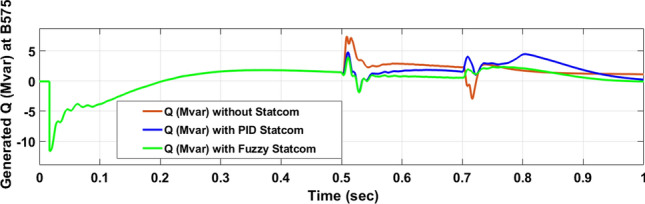
The reactive power produced at Bus 575 through LL fault without links STATCOM, with PID STATCOM control and with FLC STATCOM.
Fig. 17.

(A) The voltage at Bus 25 through LL fault without links STATCOM. (B) The voltage at Bus 25 with PID STATCOM control. (C) The voltage at Bus 25 with FLC STATCOM.
Fig. 18.

(A) The current at Bus 25 through LL fault without links STATCOM. (B) The current at B 25 with PID STATCOM control. (C) The current at B 25 with FLC STATCOM.
Fig. 19.

The voltage of DC link at Bus 575 through LL fault without links STATCOM, with PID STATCOM control and with FLC STATCOM.
Fig. 20.

Rotor speed of DFIG through LL fault without links STATCOM, with PID STATCOM control and with FLC STATCOM.
Table 4.
Comparisons of the results through LLF at B 575 V.
| Comparisons state | The active power (MW) minimum–maximum | The reactive power (MVAR) minimum–maximum | Voltage of DC link |
|---|---|---|---|
| Without STATCOM | 5.5–11.5 | − 2.85 to 7.4 | 1208 |
| With PID STATCOM | 5.3–12.44 | − 1.88 to 4.7 | 1173 |
| With Fuzzy STATCOM | 8–13 | − 1.88 to 3.5 | 1155 |
PV model
Voltage sagging occurs at PV bus at the period of fault as shown in Fig. 21A and when PID, and Fuzzy STATCOM linked voltage sag was mitigated as shown in Fig. 21B,C. Also Fig. 22A–C shows current before and after linked STATCOM to mitigate voltage swell. Figure 23 shows active power before and after linked STATCOM with PID and Fuzzy. Figure 24 shows reactive power before and after linked STATCOM with PID, Fuzzy. Figure 25 shows DC link voltage before and after connected STATCOM with PID and Fuzzy as shown in compression in Table 5.
Fig. 21.

(A) PV voltage through LL fault without STATCOM. (B) PV voltage with PID STATCOM control. (C) PV voltage with FLC STATCOM.
Fig. 22.

(A) PV current through LL fault without STATCOM. (B) PV current with PID STATCOM control. (C) PV current with FLC STATCOM.
Fig. 23.

PV active power generated through LL fault without links STATCOM, with PID STATCOM control and with FLC STATCOM.
Fig. 24.

PV reactive power generated through LL fault without links STATCOM, with PID STATCOM control and with FLC STATCOM.
Fig. 25.
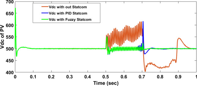
The Voltage of DC link Voltage of through LL fault without links STATCOM, with PID STATCOM control and with FLC STATCOM.
Table 5.
Comparisons of the results through LLF at PV Bus.
| Comparisons state | The active power (KW) minimum–maximum | The reactive power (KVAR) | Voltage of DC link minimum–maximum |
|---|---|---|---|
| Without STATCOM | 771–1056 | − 155 to 169.6 | 406–613 |
| With PID STATCOM | 838–1070 | − 254.5 to 824 | 477–614 |
| With Fuzzy STATCOM | 922–995 | − 210 to 214 | 479–551 |
Hybrid PV/wind
Figure 26 shows the Active power of hybrid PV/wind produced at B 25 before and after linked STATCOM in case PID and Fuzzy. Figure 27 shows reactive power before and after linked STATCOM with PID and Fuzzy. Figure 28 shows active power of load before and after linked STATCOM. Figure 29 shows reactive power of load before and after linked STATCOM with PID and Fuzzy. Figure 30 shows Vmeas Vref where Vmeas is voltage measured and Vref is voltage reference at bus STATCOM before and after STATCOM linked with PID and Fuzzy. Also Fig. 31 shows reactive power produced at bus STATCOM with PID and Fuzzy. Table 6 offers comparisons among PID and FLC to improve LVRT. Also, Table 7 offers comparisons among PID controller and FLC at STATCOM Bus to enhance LVRT.
Fig. 26.

Generated active power at Bus PCC through LL fault without links STATCOM, with PID STATCOM control and with FLC STATCOM.
Fig. 27.

Generated reactive power at Bus PCC through LL without links STATCOM, with PID STATCOM control and with FLC STATCOM.
Fig. 28.

Load active power through LL fault without links STATCOM, with PID STATCOM control and with FLC STATCOM.
Fig. 29.

Load Reactive power through LL fault without links STATCOM, with PID STATCOM control and with FLC STATCOM.
Fig. 30.

Vmeas, Vref of STATCOM through LL fault without links STATCOM, Vref, with control PID STATCOM and with FLC STATCOM.
Fig. 31.
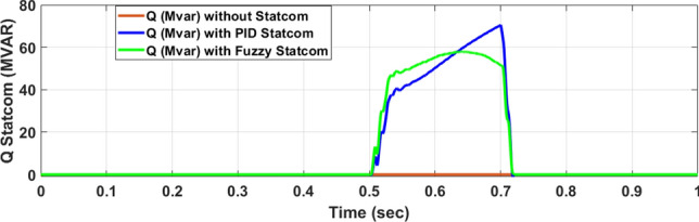
Generated reactive power at STATCOM through LL fault without STATCOM, with control PID STATCOM and with FLC STATCOM.
Table 6.
Comparisons of results through LLF at Hybrid PV/wind B 25 kV.
| Comparisons state | The active power (MW) minimum–maximum | The reactive power (MVAR) | P load (MW) | Q (MVAR) |
|---|---|---|---|---|
| Without STATCOM | 7.4–13.2 | 0 | 2.5 | 0.56 |
| With PID STATCOM | 8.58–17.1 | 62 | 4.2–10 | 1–2.2 |
| With fuzzy STATCOM | 9.5–15.8 | 69 | 8.3–10 | 1.93–2.2 |
Table 7.
Comparisons of results through LLF at STATCOM Bus.
| Comparisons state | Vmeas | Vref | Reactive power |
|---|---|---|---|
| Without STATCOM | 0.53 | 1 | 0 |
| With PID STATCOM | 0.69–1.05 | 1 | 54.5 |
| With Fuzzy STATCOM | 0.96–1.05 | 1 | 62.6 |
The limitations and future work
In the case of change in the load of the model, the parameter of the controller will change.
In the case change parameter of the three-phase transmission line with the PI section, the parameter of controller change.
In the case change in the value of the active power of the wind turbine and the power of the PV station, the parameter of the controller change.
In the case change the capacitance value of STATCOM, the parameter of the controller will change.
Conclusion
This paper studies the LVRT Issue that occurs due to line-to-line fault and its impact on a hybrid system consisting of a 9 MW wind farm and 1 MW PV station. So, the STATCOM device is used to solve this problem. The proposed STATCOM is used to compensate for reactive power and mitigate voltage dip. The PSO optimization method is applied to the PID controller to get the best PID parameter. The simulation results shows the effectiveness of suggested STATCOM in mitigation voltage dip, compensating reactive and active power of PV and wind farm, and protecting DC- Link voltage from overvoltage. In the case of line-to-line fault, STATCOM with FLC compensates for voltage by 96% compared with PID which compensates for voltage by 69%. STATCOM with FLC gives 62.6MVAR reactive power compared with STATCOM with PID, which gives 54.5 MVAR reactive power. Comparison between STATCOM PID controller and Fuzzy logic control is studied to achieve the best performance for STATCOM but FLC gives better performance than PID controller in enhancing LVRT capability, and power quality.
Author contributions
N. G. EL Sayed, A.M. Yousef, G. El-Saady, M. D. Alanazi, H. A. Ziedan, M. Abdelsattar wrote the main manuscript text, prepared and drown all figures. All authors reviewed and revised the manuscript.
Funding
Open access funding provided by The Science, Technology & Innovation Funding Authority (STDF) in cooperation with The Egyptian Knowledge Bank (EKB).
Data availability
All data generated or analyzed during this study are included in this published article.
Declarations
Competing interests
The authors declare no competing interests.
Footnotes
Publisher’s note
Springer Nature remains neutral with regard to jurisdictional claims in published maps and institutional affiliations.
References
- 1.Afzal, M. M. et al. A comparative study of supercapacitor-based STATCOM in a grid-connected photovoltaic system for regulating power quality issues. Sustainability12(17), 6781. 10.3390/su12176781 (2020). [Google Scholar]
- 2.Abdelsattar, M., Mesalam, A., Diab, A. A. Z., Fawzi, A. & Hamdan, I. Optimal sizing of a proposed stand-alone hybrid energy system in a remote region of southwest Egypt applying different metaheuristic algorithms. Neural Comput. Appl.36, 16251–16269. 10.1007/s00521-024-09902-9 (2024). [Google Scholar]
- 3.Abdelsattar, M., Mesalam, A., Fawzi, A. & Hamdan, I. Mountain gazelle optimizer for standalone hybrid power system design incorporating a type of incentive-based strategies. Neural Comput. Appl.36, 6839–6853. 10.1007/s00521-024-09433-3 (2024). [Google Scholar]
- 4.Abdelsattar, M., Ismeil, M. A., Aly, M. M. & Abu-Elwfa, S. S. Analysis of renewable energy sources and electrical vehicles integration into microgrid. IEEE Access12, 66822–66832. 10.1109/ACCESS.2024.3399124 (2024). [Google Scholar]
- 5.Abdelsattar, M., Ismeil, M. A., Azim Zayed, M. M. A., Abdelmoety, A. & Emad-Eldeen, A. Assessing machine learning approaches for photovoltaic energy prediction in sustainable energy systems. IEEE Access12, 107599–111076. 10.1109/ACCESS.2024.3437191 (2024). [Google Scholar]
- 6.Abdelsattar, M. et al. Optimal integration of photovoltaic and shunt compensator considering irradiance and load changes. Comput. Electr. Eng.97, 107658. 10.1016/j.compeleceng.2021.107658 (2022). [Google Scholar]
- 7.Abd El Sattar, M., Hafez, W. A., Elbaset, A. A. & Alaboudy, A. H. K. Economic valuation of electrical wind energy in Egypt based on levelized cost of energy. Int. J. Renew. Energy Res.10(4), 1879–1891 (2020). [Google Scholar]
- 8.Abdelsattar, M., Ismeil, M. A., Aly, M. M. & Abu-Elwfa, S. S. Energy management of microgrid with renewable energy sources: A case study in Hurghada Egypt. IEEE Access12, 19500–19509 (2024). [Google Scholar]
- 9.Boubii, C. et al. Integrated control and optimization for grid-connected photovoltaic systems: A model-predictive and PSO approach. Energ. J.16(21), 2–22. 10.3390/en16217390 (2023). [Google Scholar]
- 10.Wang, P.-K. et al. Harris Hawks optimization-based algorithm for STATCOM voltage regulation of offshore wind farm grid. Energ. J.15(9), 2–24. 10.3390/en15093003 (2022). [Google Scholar]
- 11.Soued, S., Ramadan, H. S. & Becherif, M. Effect of doubly fed induction generator on transient stability analysis under fault conditions. Energy Proc.162, 315–324 (2019). [Google Scholar]
- 12.Sabzevari, K. et al. Low-voltage ride-through capability in a DFIG using FO-PID and RCO techniques under symmetrical and asymmetrical faults. Sci. Rep.13(1), 17534. 10.1038/s41598-023-44332-y (2023). [DOI] [PMC free article] [PubMed] [Google Scholar]
- 13.Senapati, M. K., Pradhan, C., Samantaray, S. R. & Nayak, P. K. Improved power management control strategy for renewable energy-based DC micro-grid with energy storage integration. IET Gener. Transm. Distrib.13(6), 838–849. 10.1049/iet-gtd.2018.5019 (2018). [Google Scholar]
- 14.Senapati, M. K., Pradhan, C. & Calay, R. K. A computational intelligence based maximum power point tracking for photovoltaic power generation system with small-signal analysis. Wiley J.44(1), 1–29. 10.1002/oca.2798 (2021). [Google Scholar]
- 15.Senapati, M. K. et al. Advancing electric vehicle charging ecosystems with intelligent control of DC microgrid stability. IEEE Trans. Ind. Appl.10.1109/TIA.2024.3413052 (2024). [Google Scholar]
- 16.Senapati, M. K., Pradhan, C., Nayak, P. K., Padmanaban, S. & Gjengedal, T. Modified demagnetisation control strategy for low-voltage ride-through enhancement in DFIG-based wind systems. IET Renew. Power Gener. Inst. Eng. Technol.14(17), 3487–3499. 10.1049/iet-rpg.2019.1128 (2020). [Google Scholar]
- 17.Senapati, M. K., Paira, S., Dehury, S. & Nayak, S. Two stage three-phase grid-connected hybrid photovoltaic-wind system. In 2022 IEEE 2nd International Symposium on Sustainable Energy, Signal Processing and Cyber Security (iSSSC) (2022). 10.1109/iSSSC56467.2022.10051371
- 18.Senapati, M. K., Pradhan, C., Nayak, P. K. & Samantaray, S. R. Lagrange interpolating polynomial-based deloading control scheme for variable speed wind turbines. Wiley J.29(2824), 1–17. 10.1002/2050-7038.2824 (2018). [Google Scholar]
- 19.Singh, S., Saini, S., Gupta, S. K. & Kumar, R. Solar-PV inverter for the overall stability of power systems with intelligent MPPT control of DC-link capacitor voltage. Protect. Control Mod. Power Syst.8(15), 2–20. 10.1186/s41601-023-00285-y (2023). [Google Scholar]
- 20.Kumar, R., Diwania, S., Khetrapal, P. & Singh, S. Performance assessment of the two metaheuristic techniques and their hybrid for power system stability enhancement with PVSTATCOM. Neural Comput. Appl.34, 3723–3744. 10.1007/s00521-021-06637-9 (2022). [Google Scholar]
- 21.Kumar, R. et al. An intelligent hybrid wind–PV farm as a static compensator for overall stability and control of multimachine power system. ISA Trans.123, 286–302. 10.1016/j.isatra.2021.05.014 (2022). [DOI] [PubMed] [Google Scholar]
- 22.Kumar, R., Diwania, S., Khetrapal, P., Singh, S. & Badoni, M. Multimachine stability enhancement with hybrid PSO-BFOA based PV-STATCOM. Sustain. Comput. Inf. Syst.32, 100615. 10.1016/j.suscom.2021.100615 (2021). [Google Scholar]
- 23.Eswaran, T. & Suresh Kumar, V. Particle swarm optimization (PSO)-based tuning technique for PI controller for management of a distributed static synchronous compensator (DSTATCOM) for improved dynamic response and power quality. J. Appl. Res. Technol.15(2), 2–17. 10.1016/j.jart.2017.01.011 (2017). [Google Scholar]
- 24.Adetokun, B. B. & Muriithi, C. M. Application and control of flexible alternating current transmission system devices for voltage stability enhancement of renewable-integrated power grid: A comprehensive review. Heliyon J.7(3), 2–7. 10.1016/j.heliyon.2021.e06461 (2021). [DOI] [PMC free article] [PubMed] [Google Scholar]
- 25.Koohi-Kamali, S., Tyagi, V. V., Rahim, N. A., Panwar, N. L. & Mokhlis, H. Emergence of energy storage technologies as the solution for reliable operation of smart power system: A review. Renew. Sustain. Energy Rev.25, 135–165. 10.1016/j.rser.2013.03.056 (2013). [Google Scholar]
- 26.Kamel, O. M., Diab, A. A. Z., Do, T. D. & Mossa, M. A. A novel hybrid ant colony-particle swarm optimization techniques based tuning STATCOM for grid code compliance. IEEE Access8, 41566–41587. 10.1109/ACCESS.2020.2976828 (2020). [Google Scholar]
- 27.Moufid, I. et al. Impact of static synchronous compensator STATCOM installation in power quality improvement. Int. J. Power Electron. Drive Syst.13(4), 2296–2304. 10.11591/ijpeds.v13.i4 (2022). [Google Scholar]
- 28.Sengupta, S., Kumar, A. & Tiwari, S. Transient stability enhancement of a hybrid WindPV farm incorporating a STATCOM. In IEEE International Conference on Recent Trends in Electronics, Information & Communication Technology (RTEICT-2018) in India 1574–1580 (2018). 10.1109/RTEICT42901.2018.9012385
- 29.Hatata, A. Y., Hasan, E. O., Alghassab, M. A. & Sedhom, B. E. Centralized control method for voltage coordination challenges with OLTC and D-STATCOM in smart distribution networks based IoT communication protocol. IEEE Access11, 11903–11922. 10.1109/ACCESS.2023.3242236 (2023). [Google Scholar]
- 30.Neamah, N. M., AbuHussein, A., Hossam-Eldin, A. A., Alghamdi, S. & AboRas, K. M. Improvement of frequency regulation of a wind-integrated power system based on a PD-PIDA controlled STATCOM tuned by the artificial rabbits optimizer. IEEE Access11, 55716–55735. 10.1109/ACCESS.2023.3277202 (2023). [Google Scholar]
- 31.Sarwar, M. et al. Stability enhancement of grid-connected wind power generation system using PSS, SFCL and STATCOM. IEEE Access11, 30832–30844. 10.1109/ACCESS.2023.3262172 (2023). [Google Scholar]
- 32.Zheng, Z. et al. A continuous fault ride-through scheme for DFIGs under commutation failures in LCC-HVDC transmission systems. J. Mod. Power Syst. Clean Energy11(4), 1127–1135. 10.35833/MPCE.2021.000441 (2023). [Google Scholar]
- 33.Abdelsattar, M. et al. Voltage stability improvement of an Egyptian power grid-based wind energy system using STATCOM. Wind Energy25(6), 1077–1120. 10.1002/we.2716 (2022). [Google Scholar]
- 34.Napole, C. et al. Double fed induction generator control design based on a fuzzy logic controller for an oscillating water column system. Energies14(12), 1–19. 10.3390/en14123499 (2021). [Google Scholar]
- 35.Sahri, Y. et al. Performance improvement of hybrid system based DFIG-wind/PV/batteries connected to DC and AC grid by applying intelligent control. Energy Rep.9, 2027–2043. 10.1016/j.egyr.2023.01.021 (2023). [Google Scholar]
- 36.Oda, E. S. et al. Optimal allocation of a hybrid photovoltaic-based DG and DSTATCOM under the load and irradiance variability. Int. Trans. Electr. Energ Syst.31, 1–25. 10.1002/2050-7038.13131 (2021). [Google Scholar]
- 37.Abd El Hamed, A. M., Ebeed, M., Abd El Sattar, M., Elbaset, A. A. & Kamel, S. Optimal allocation of PV and DSTATCOM for enhancing the power quality of east delta egyptian distribution network. Int. J. Adv. Sci. Technol.28(15), 79–88 (2019). [Google Scholar]
- 38.Alaboudy, A. H. K., Elbaset, A. A. & Abdelsattar, M. A case study on the LVRT capability of an Egyptian electrical grid linked to the Al-Zafarana wind park using series resistor. Int. J. Renew. Energy Res.13(1), 37–48. 10.20508/ijrer.v13i1.13718.g8659 (2023). [Google Scholar]
- 39.Muisyo, I. N., Muriithi, C. M. & Kamau, S. I. Enhancing low voltage ride through capability of grid connected DFIG based WECS using WCA-PSO tuned STATCOM controller. Heliyon8(8), 1–12. 10.1016/j.heliyon.2022.e09999 (2022). [DOI] [PMC free article] [PubMed] [Google Scholar]
- 40.Yameen, M. Z. et al. Improvement of LVRT capability of grid-connected wind-based microgrid using a hybrid GOA-PSO-tuned STATCOM for adherence to grid standards. IET Renew. Power Gener.18, 3218–3238. 10.1049/rpg2.13036 (2024). [Google Scholar]
- 41.El Khlifi, Y., El Magri, A., Mansouri, A. & Lajouad, R. Enhanced low voltage ride-through control of multilevel flying capacitor inverter based wind generation. Indonesian J. Electr. Eng. Comput. Sci.33(2), 854–861. 10.11591/ijeecs.v33.i2.pp854-861 (2024). [Google Scholar]
- 42.Wang, Z., Jialiang, Wu., Liu, R. & Shan, Yu. A P-Q coordination control strategy of VSC-HVDC and BESS for LVRT recovery performance enhancement. Electronics13(741), 2–22. 10.3390/electronics13040741 (2024). [Google Scholar]
- 43.Dösoglu, M. K. & Dogan, M. U. Enhancement of low voltage ride through (LVRT) capability of DFIG-based wind turbines with enhanced demagnetization control model. Energies17, 4015. 10.3390/en17164015 (2024). [Google Scholar]
- 44.Mosaad, M. I., Ramadan, H. S., Aljohani, M., Sherif, M.F.E.-N. & Ghoneim, S. S. M. Near-optimal PI controllers of STATCOM for efficient hybrid renewable power system. IEEE Access9, 34119–34130 (2021). [Google Scholar]
- 45.Sayahi, K., Kadri, A., Bacha, F. & Marzougui, H. Implementation of a D-STATCOM control strategy based on direct power control method for grid connected wind turbine. Int. J. Electr. Power Energy Syst.121, 1–14. 10.1016/j.ijepes.2020.106105 (2020). [Google Scholar]
- 46.Hamdan, I., Ibrahim, A. M. & Noureldeen, O. Modifed STATCOM control strategy for fault ride-through capability enhancement of grid-connected PV/wind hybrid power system during voltage sag. SN Appl. Sci.2, 364. 10.1007/s42452-020-2169-6 (2020). [Google Scholar]
- 47.Nafeh, A. A., Heikal, A., El-Sehiemy, R. A. & Salem, W. A. Intelligent fuzzy-based controllers for voltage stability enhancement of AC-DC micro-grid with D-STATCOM. Alexandria Eng. J.36(3), 2–34. 10.1016/j.aej.2021.07.012 (2021). [Google Scholar]
- 48.Reddy, C. R., Goud, B. S., Aymen, F., Rao, G. S. & Bortoni, E. C. Power quality improvement in HRES grid connected system with FOPID based atom search optimization technique. Energies14(18), 5812. 10.3390/en14185812 (2021). [Google Scholar]
- 49.Alshehri, J. & Khalid, M. Power quality improvement in microgrids under critical disturbances using an intelligent decoupled control strategy based on battery energy storage system. IEEE Access7, 147314–147326. 10.1109/ACCESS.2019.2946265 (2019). [Google Scholar]
- 50.Sarita, K. et al. Power enhancement with grid stabilization of renewable energy-based generation system using UPQC-FLC-EVA technique. IEEE Access8, 207443–207464. 10.1109/ACCESS.2020.3038313 (2020). [Google Scholar]
- 51.Emambocus, B. A. S., Jasser, M. B. & Amphawan, A. A survey on the optimization of artificial neural networks using swarm intelligence algorithms. IEEE Access11, 1280–1294. 10.1109/ACCESS.2022.3233596 (2023). [Google Scholar]
- 52.Baños, R. et al. Optimization methods applied to renewable and sustainable energy: A review. Renew. Sustain. Energy Rev.15(4), 1753–1766. 10.1016/j.rser.2010.12.008 (2011). [Google Scholar]
- 53.Kasem Alaboudy, A. H., Mahmoud, H. A., Elbaset, A. A. & Abdelsattar, M. Improved LVRT techniques for grid-connected DFIG wind turbines: A technical review. SVU-Int. J. Eng. Sci. Appl.4(2), 7–23. 10.21608/SVUSRC.2023.180183.1089 (2023). [Google Scholar]
- 54.Rini Ann Jerin, A., Prabaharan, N., Palanisamy, K. & Umashankar, S. FRT capability in DFIG based wind turbines using DVR with combined feed-forward and feed-back control. Energy Procedia38, 1184–1189. 10.1016/j.egypro.2017.10.233 (2017). [Google Scholar]
- 55.Mosayyebi, S. R., Shahalami, S. H. & Mojallali, H. Fault ride-through capability improvement in a DFIG-based wind turbine using modifed ADRC. Protect. Control Mod. Power Syst.7(4), 2–27. 10.1186/s41601-022-00272-9 (2022). [Google Scholar]
- 56.Qais, M. H., Hasanien, H. M. & Alghuwainem, S. Whale optimization algorithm-based Sugeno fuzzy logic controller for fault ride-through improvement of grid-connected variable speed wind generators. Eng. Appl. Artif. Intell.87, 103328. 10.1016/j.engappai.2019.103328 (2020). [Google Scholar]
- 57.Napole, C. et al. Double fed induction generator control design based on a fuzzy logic controller for an oscillating water column system. Energies14(12), 3499. 10.3390/en14123499 (2021). [Google Scholar]
- 58.Pang, C. & Kezunovic, M. A new approach to PID controller design of STATCOM. In Power System Engineering Research 1–6 (2008).
- 59.Eshtehardiha, S., Poodeh, M. B. & Kiyoumarsi, A. Optimized performance of STATCOM with PID controller based on genetic algorithm. In International Conference on Control, Automation and Systems in Korea (South) 1639–1644 (2007).
- 60.Aghababa, M. P. Optimal design of fractional-order PID controller for five bar linkage robot using a new particle swarm optimization algorithm. Soft Comput.20(10), 4055–4067 (2016). [Google Scholar]
- 61.Cai, X., Cui, Z., Zeng, J. & Tan, Y. Self-adaptive PID-controlled particle swarm optimization. Control Conf.1(4), 799–803 (2007). [Google Scholar]
- 62.Tang, J., Liu, G. & Pan, Q. A review on representative swarm intelligence algorithms for solving optimization problems: Applications and trends. IEEE/CAA J. Automatica Sinica8(10), 1627–1642. 10.1109/JAS.2021.1004129 (2021). [Google Scholar]
- 63.Dhivya, S. Control strategy for a STATCOM with and without load condition. Malaya J. Matematik8(2), 3442–3448. 10.26637/MJM0S20/0893 (2020). [Google Scholar]
- 64.Alsammak, A. N. & Mohammed, H. A. A comparison study of the most important types of the flexible alternating current transmission systems (FACTs). Al-Rafidain Eng. J.25(1), 49–55 (2020). [Google Scholar]
- 65.Hafez, W. A., Abd El Sattar, M., Kasem Alaboudy, A. H. & Elbaset, A. A. Power quality issues of grid connected wind energy system focus on DFIG and various control techniques of active harmonic filter: A review. In 2019 21st International Middle East Power Systems Conference (MEPCON) in Egypt (2019). 10.1109/MEPCON47431.2019.9008171
- 66.Mosaad, M. I., Ramadan, H., Aljohani, M. & El-Naggar, M. Near-optimal PI controllers of STATCOM for efficient hybrid renewable power system. IEEE Access9, 34119–34130. 10.1109/ACCESS.2021.3058081 (2021). [Google Scholar]
- 67.Adenegsan, K. & Shi, J. Improving power quality and stability of wind energy conversion system with fuzzy-controlled STATCOM. Aust. J. Electr. Electron. Eng.12(3), 1–10 (2015). [Google Scholar]
- 68.Abd El-Hameid, A. M., Elbaset, A. A., Ebeed, M. & Abdelsattar, M. Enhancement of Grid-Connected Photovoltaic Systems Using Artificial Intelligence 243 (Springer, 2023). 10.1007/978-3-031-29692-5. [Google Scholar]
- 69.Sayed, N. G. E. L. et al. Artificial intelligent fuzzy control and LAPO algorithm for enhancement LVRT and power quality of grid connected PV/wind hybrid systems. Sci. Rep.14(1), 30475. 10.1038/s41598-024-78384-5 (2024). [DOI] [PMC free article] [PubMed] [Google Scholar]
Associated Data
This section collects any data citations, data availability statements, or supplementary materials included in this article.
Data Availability Statement
All data generated or analyzed during this study are included in this published article.