

Abstract
There are light impurities in isotopes that may leak from the air or be generated by reactions in the pipelines. When separating isotopes, these light impurities will affect the quality of the isotopes. Using a rotating cylinder to separate isotopes and impurity gases with a mass number difference by inertial force is one of the green and environmentally friendly as well as effective ways. It is meaningful to obtain the working mechanism of gas purification by the rotating cylinder through numerical simulation and study the optimization direction of the performance of the rotating cylinder so as to make the purification of gases by the rotating cylinder more efficient. This study analyzes the separation characteristics of the gas mixture of C7F14 and N2 in the rotating cylinder. A hydrodynamic model of the binary gas mixture with sources and sinks is constructed. By employing an iterative approach to simultaneously solve the flow equation and the diffusion equation under strong perturbation, the flow field and the concentration distribution of the binary gas mixture within the rotating cylinder can be obtained. This study explores the impact of various factors on the total separation factor of gas mixture with large mass difference. The numerical results demonstrate that the binary gas mixture with a large mass difference in the rotating cylinder will still exhibit the radial separation characteristics under the action of strong driving circulation under the condition of having mass sources and sinks. The driving amount and the size of the scoop inlet have a regular influence on the total separation factor of the gas mixture.
Keywords: Rotating cylinder, Large mass difference, Gas mixture, Numerical simulation
Subject terms: Fluid dynamics, Nuclear fuel
Introduction
The production of isotopes using rotating cylinders inevitably results in the generation of light gases, which can be attributed to the inherent properties of the raw material or the intrinsic characteristics of the process itself. The introduction of light gases will impact the efficiency of isotope enrichment by rotating cylinder. Furthermore, the elevated concentration of light gases will result in an increase in the power consumption of the rotating cylinder, which may potentially compromise the safe operation of the equipment1–4. A novel type of rotating cylinder has been devised with the objective of removing light gases from the feedstock, thereby facilitating the introduction of purified isotopes to the original equipment. It is of great importance to investigate the separation characteristics of gas mixtures with large mass different in a strong rotating flow field in order to gain a comprehensive understanding of the design parameters of the innovative rotating cylinder, which is capable of effectively removing light gases.
In the study of gas mixtures flowing through a strong rotating flow field, the flow equations are typically solved for a single gas. The resulting flow parameters are then incorporated into the diffusion equation, which is solved in order to determine the component distribution. However, for fluids exhibiting significant disparities in mass and physicochemical properties that cannot be regarded as a single gas, it is essential to solve the flow equation and the diffusion equation in a coupled manner5–10. In the published literature, Kai11 employed a modified Newton’s method to solve the flow equation coupled with the diffusion equation, thereby obtaining a converged solution at low rotational speeds with small perturbations. Zheng12 adopted a method similar to that of Kai and obtained the property that the gas mixture with a large mass difference exhibits radial separation in the rotating cylinder. Besides, Zheng also studied the physical principles of the separation of gas mixtures in the rotating cylinder. However, the conclusions obtained in his paper were qualitative, and there was no obvious pattern in the calculated gas separation characteristics. Abramov13 calculated the separation characteristics of gas mixture with large mass difference in a rotating cylinder based on a single-fluid physical model, with a relatively low feed concentration of the light gases in the illustrative calculation. Songjie Tian14 investigated the impact of individual driving quantities on the flow field and concentration distribution of gas mixtures with a large mass different in the absence of mass sources and sinks.
In general, there is a paucity of literature investigating the separation characteristics of gas mixtures in strong rotating flow fields by coupling the solution of the flow and diffusion equations. Moreover, the examples with mass sources and sinks are only applicable under specific conditions. This paper takes C7F14 and N2 as the research object and establishes the nonlinear hydrodynamic equations for a binary gas mixture with sources and sinks. Then, we examine the fixed solution conditions that are applicable to the solution of this set of equations. After that, the coupled flow and diffusion equations are solved in order to obtain a solution to this set of nonlinear hydrodynamic equations. Next, the distribution of the flow field and the concentration of the gas mixture within a rotating cylinder are presented. Finally, the impact of varying drive quantities and component dimensions on the performance of the rotating cylinder was simulated.
Fluid dynamics of binary gas mixtures models
System of hydrodynamic equations for binary gas mixture
The flow inside the rotating cylinder is very complex15–17, and the establishment of the hydrodynamic equations for the binary gas mixture is based on the following assumptions:
(1) The gas mixture in the rotating cylinder is a continuous medium, the flow is laminar, and its motion satisfies the Navier-Stokes law;
(2) The gas mixture in the rotating cylinder is an isotropic Newtonian fluid and satisfies the perfect gas equation of state;
(3) The Stokes approximation is adopted and its bulk viscosity coefficient is ignored, and at the same time, its thermodynamic properties obey Fourier’s law;
(3) The steady state is considered, and the gas flow is axisymmetric, and gravity is negligible compared with inertial forces;
(4) The heat transferred to the fluid due to radiation or other reasons is ignored.
After introducing the above assumptions, the N-S equations describing the conservation laws of gas flow in the rotating cylinder are as follows:
 |
1 |
 |
2 |
 |
3 |
 |
4 |
 |
5 |
 |
6 |
Equation (1) to (6) form the set of fluid dynamic equations for binary gas mixture with mass sources and sinks. where r and z are the radial and axial coordinates;  and
and  are the densities of the binary gas mixture; M1 and M2 are the molar masses of the two gases; T is the temperature of the gas mixture; u, v and w are the constant volume heat capacities of the two gases;
  and
and  are the source-sink terms for the gas mixture and light gas, respectively;
  is the friction drive in the angular direction for the waste scoop,
  , and the CD is a friction coefficient given artificially;
  is the number of moles of mixed gas per unit volume;
  is the gas constant; Cv1 and Cv2 are the constant volume heat capacities of the two components;
  is the heat transfer coefficient of the gas mixture;
  is the viscosity coefficient which considers the gas mixture as a gas with a miscibility coefficient; D12 is the binary diffusion coefficient. The physical parameters of the gas mixture are considered as functions of concentration and temperature and are corrected in iterative calculations using the same method as in the literature14 until the accuracy of the calculations is satisfactory.
Treatment of mass sources and sinks
In numerical simulations of rotating cylinder flow fields, it is common practice to introduce sources and sinks into the governing equations in order to characterize the effect of feed and withdrawal on the conservation of mass in the flow field18,19. In the investigation of the separation of gas mixtures with isotopes in a rotating cylinder, it is assumed that the differences in mass concentration and molar concentration between the isotopes are minimal and do not specifically differentiate between the isotopes. However, there are notable discrepancies in the mass concentration and molar concentration of the gas mixtures with large differences in the mass, which must be explicitly delineated. In the experiment, the feed concentration of the light gas is expressed in molar terms, whereas the source terms of the control equation are represented by mass concentration. It is therefore essential to be able to convert between molar and mass concentration, as this is a crucial aspect of the treatment of the source terms. The source-sink terms for the feed outlet, the product scoop inlet and the waste scoop inlet are expressed as follows:
In regard to the feed outlet, the source terms for the gas mixture and the light gas are as follows:
 |
7 |
 |
8 |
At the product scoop inlet, the sink terms of the gas mixture and light gas are as follows:
 |
9 |
 |
10 |
At the waste scoop inlet, the sink terms of the gas mixture and light gas are as follows:
 |
11 |
 |
12 |
Among them:
 |
13 |
 |
14 |
The total feed flow rate of the gas mixture is represented by the variable F; the mass concentration of the binary gas mixture is represented by the variable  ; the molar concentration of the first gas and the second gas in the feed are represented by the variable
  and
and  ; the total molar amount of the gas mixture is represented by the variable
  ; the molar split ratio is represented by the variable
  ; the densities of the first gas and the second gas in the product scoop inlet are represented by the variables
  and
and  ; the densities of the first gas and the second gas in the waste scoop inlet are represented by the variables
  and
and  .
.
Boundary conditions and deterministic conditions
Boundary conditions
Figure 1 depicts a schematic representation of the axisymmetric model of a rotating cylinder, wherein the computational domain encompasses the viscous flow area to which the Navier–Stokes equations are applicable20,21. In the viscous flow region, F represents the feed flow, P denotes the product flow, and W signifies the waste flow.
Fig. 1.

Schematic diagram of an axisymmetric calculation model of a rotating cylinder.
It is essential to define the boundary conditions at the boundary of the computational domain. In this instance, a no-slip boundary condition has been implemented for both velocity and temperature at the solid wall boundary.
 |
15 |
Where  is the angular velocity of the wall and
  is the wall temperature.
The natural boundary conditions at the center of the axis are applied to the inner boundary:
 |
16 |
In order to guarantee that the gas mixture displays no diffusive flux at the boundary of the computational domain, it is essential to impose the following equation on the density boundary conditions of the two components:
 |
17 |
 |
18 |
In the calculation, the thermal drive is realized by applying boundary conditions to the wall. The thermal drive is linearly distributed and  is the temperature difference between the top end plate and bottom end plate.
Fixed solution conditions
The continuity and diffusion equations remain linearly related following the application of the boundary condition discretization. Therefore, the fixed solution conditions must be applied to constrain the set of hydrodynamic equations. In the case of binary gas mixtures with mass sources and sinks, the sources and sinks themselves act as constraints on the hydrodynamic equations. Upon derivation, it was found that the continuity equation is linearly related to the mass sources and sinks constraints of the diffusion equation. It was established that the sources and sinks can only function as one of the constraints, necessitating the introduction of an additional constraint to ensure the solution is fixed. This study considers the isothermal rigid body state of the heavy gas as an initial state of the rotating cylinder, and then takes the initial retention amount of the heavy gas as an additional fixe
 |
19 |
The sources and sinks constraints of Eq. (7) to (14) and the retention volume condition for first gas in Eq. (19) collectively define the fixed solution conditions for the set of hydrodynamic equations simulating binary gas mixtures.
Model verification and comparison with previous studies
This paper simulates the flow field of a mixture of isotopes and light impurities. When the concentration of light impurities is low enough, it can be considered that there is only one substance. Zhang15 and Wood22 have conducted analysis and verification on the flow field containing only isotopes in their research. Figure 2 shows the mass flow density distribution  on the interface at z = Z/2 of rotating cylinders with three different rotational speeds (400 m/s, 500 m/s, 700 m/s) under the action of temperature difference with a magnitude of
  T = 1 K. The radial distribution of
  given in Zhang’s paper is shown in Fig. 2a. For comparison, the corresponding results calculated in this paper under the condition that the concentration of light impurities is 1‰ are shown in Fig. 2b. In the figure, the abscissa adopts the dimensionless reduced density scale
  .
.
Fig. 2.

Mass flow density distribution on the Z/2 section of the rotating cylinder.
By comparing the forms, zero-point positions and amplitudes of the pw-x curves of the model in Zhang’s paper and that in this paper, it can be found that they match well, which proves the correctness of the model.
At present, the numerical studies on simulating the flow field of gas mixtures in a strong swirling flow field by coupling and solving the flow equation and the diffusion equation can only be found in the literature of Kai11 and Zheng Zhi12. Kai studied the separation characteristics of the mixed gas at a low rotational speed of 200 m/s. The Fig. 3 shows the variation of the flow density on the z = Z/2 section with the number of grids, which is based on Kai’s model. As shown in the figure, when the number of grids is 42 × 76, with a total of 3,192 grids, there is an obvious difference between the flow density curve and that when the number of grids is 46,000. However, in Kai’s model, the number of grids given is only 16 × 43, with a total of 688 grids, which is even fewer. The qualitative research on the flow field of the mixture gas in Kai’s paper is inspiring for future scholars’ research on this issue. However, the number of grids in the model is too small and the rotational speed is relatively low, so more qualitative conclusions are given and it is impossible to conduct quantitative research.
Fig. 3.
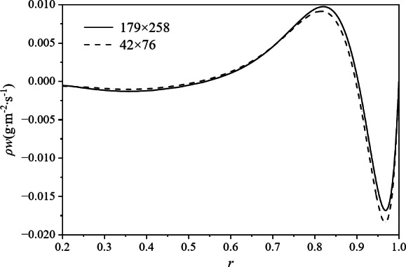
The variation of flow density on the z = Z/2 section with the number of grids.
Examples 1 and 2 in Table 1 are the quantitative calculation results in Zheng ‘s paper, while Examples 3 and 4 are the results of numerical simulations conducted in this paper based on the model parameters in Zheng ‘s paper. The feed flow rates in Zheng ‘s paper and this paper have been made dimensionless with different parameters, and the dimensionless parameter in this paper is F0. The simulation results of Example 3 in this paper are basically similar to those of Example 1 in Zheng ‘s paper. However, in Example 2, compared with Example 1, only the feed flow rate is reduced. In Zheng ‘s paper, the concentration of light impurities in both the product and the waste are lower than the concentration of light impurities in the feed, which is not in line with physical reality. In this paper, the feed flow rate in Example 4 is reduced by 10 times compared with that in Example 3 under a lower feed flow rate, and there is no significant change in the concentration of light impurities in the light and heavy fractions.
Table 1.
The calculation results of Zheng Zhi and this paper.
| case | Total feed flow rate | The concentration of light gas in the feed | The concentration of light gas in the product | The concentration of light gas in the waste |
|---|---|---|---|---|
| 1 | 3.5989e-4 | 0.1 | 0.1871 | 0.0191 |
| 2 | 3.5993e-5 | 0.1 | 0.0590 | 0.0046 |
| 3 | 0.1F0 | 0.1 | 0.1818 | 0.0181 |
| 4 | 0.01F0 | 0.1 | 0.1819 | 0.0180 |
To sum up, in the publicly published literature regarding the simulation of the separation characteristics of gas mixtures with a large mass difference in a strong rotating flow field, all the obtained results are qualitative ones simulated under specific conditions (such as low rotational speed, small driving amount, a small number of grids, and possible non-conservation of the mass of feed and discharge, etc.). Some analyses of the flow field have been carried out in the literature, but no quantitative research on the simulation results has been conducted.
Numerical simulation results of binary gas mixture in a strong rotating flow field
In this paper, the binary gas mixture of C7F14 and N2 was studied. Table 2 shows the parameters of the arithmetic example used for numerical simulation, which is based on the data from reference14. The dimensions of the components are dimensionless using the radius of the special equipment ra as a parameter.
Table 2.
The main parameters of the rotating cylinder in Zhang’s paper.
| Cylinder radius(cm) | Cylinder height(cm) | Mean temperature  (K) (K) |
Sidewall pressure(Torr) |
|---|---|---|---|
| 9.145 | 335.3 | 300 | 100 |
Based on the model parameters in Table 3, this paper conducts solutions on grids of 225 × 301 and 284 × 372 respectively. By comparing the radial distribution of the flow density on the cross-section where z = Z/2, as shown in Fig. 4, the numerical solutions before and after grid refinement are almost exactly the same.
Table 3.
Parameters used in examples.
| Parameter name | Retrieve a value |
|---|---|
| Cylinder radius | 1 |
| Cylinder height | 7.692 |
| Inner Boundary Radius | 0.83 |
| Speed of cylinder (m/s) | 600 |
| Axial center distance of feed outlet | 3.846 |
| Radial center distance of the product inlet | 0.907 |
| Radial center distance of the waste inlet | 0.920 |
| The molecular weight of C7F14(g/mol) | 350 |
| The molecular weight of N2(g/mol) | 28 |
| The sidewall pressure of the heavy gas(torr) | 100 |
| split ratio | 0.5 |
| Average sidewall temperature (K) | 300 |
| Temperature drive (K) | 10 |
| Friction coefficient | 0.01 |
| Light gas concentration (%) | 10 |
Fig. 4.

The variation of flow density on the z = Z/2 section with the number of grids.
In order to investigate the influence of different factors on the performance of the rotating cylinder, the total separation factor q is introduced as a parameter to characterize the performance of the rotating cylinder23,24. The concentration of the light gas in the product is designated as xp, while the concentration of the light gas in the waste is designated as xw. The total separation factor q is defined by the following equation:
 |
20 |
Next, the concentration of light gas at the product and the waste in the rotating cylinder and the total separation factor were compared under different mesh quantities respectively. The comparison of the calculation results on the two types of meshes is shown in the Table 4. The deviation of the calculated values of the concentration at the product and waste are within 1‰, while the deviation of the total separation factor is within 1%. Such grid precision is sufficient for the performance analysis of the rotating cylinder in gas purification.
Table 4.
Mesh error analysis.
| Mesh quantity | Concentration of light gas at the product | Concentration of light gas at the waste | Total separation factor |
|---|---|---|---|
| 225 × 301 | 18.4607 | 1.5675 | 14.2174 |
| 284 × 372 | 18.4615 | 1.5664 | 14.2280 |
Flow field and concentration distribution of the binary gas mixture
As illustrated in Fig. 5, C7F14 has a relatively high molecular weight. When the rotating cylinder operates at a high rotational speed, it will be compressed by inertial forces into a very thin layer close to the sidewall. The vertical boundary layer near the side wall is named the Stewardson layer25,26, and C7F14 forms an axial circulation within the Stewardson layer close to the side wall of the cylinder. In contrast, N2 has a smaller molecular weight and presents a more extensive circulation throughout the entire computational domain.
Fig. 5.

Streamline diagram of the binary gas mixture.
Figure 6 illustrates the molar concentration distribution of N2 in the exemplar gas mixture. The concentration distribution of the light gas exhibits a more pronounced radial gradient and a less pronounced axial gradient, which is analogous to the trend observed in the concentration distribution of the light components in the absence of feed and extraction.
Fig. 6.

Molar concentration diagram of N2 in examples.
Effect of each drive quantity on the performance of rotating cylinder
Figure 7 depicts the variation curves of the total separation factor and the maximum circulation density of the gas mixture when the feed flow rate, the temperature drive and the friction drive act independently. As shown in Fig. 7, an increase in the feed flow rate will lead to a gradual decline in the total separation factor of the gas mixture. When the feed flow rate is adjusted within the range from F0 to 3F0, the maximum variation amplitude of the overall separation factor is 2%. On the other hand, an increase in the temperature drive will cause the total separation factor of the gas mixture to rise. When the sidewall temperature difference is adjusted within the range from 2 K to 10 K, the maximum variation of the total separation factor is 20%. Besides, an increase in the friction drive will also make the total separation factor of the gas mixture increase. When the friction drive coefficient CD changes within the range from 0.01 to 0.05, the maximum variation of the total separation factor is 7%. The above phenomena can be attributed to the influence of the drive quantity on the circulation. In the figure, when the feed flow rate is adjusted, the maximum circulation density only changes within the range of 1‰. However, changes in the temperature drive and the mechanical drive coefficient can make the circulation density vary within a relatively large range. It can thus be concluded that the performance of the rotating cylinder is closely related to the intensity of the circulation under the influence of the drive quantity. If the circulation is greatly affected, the performance will also have a large range of variations.
Fig. 7.

The variation of the total separation factors of gas mixture with difference driving parameters. a - feed flow rate; b - temperature drive; c - friction drive coefficients.
Table 5 presents the flow rate and concentration of C7F14 and N2 separated by the rotating cylinder under different temperature conditions based on the parameters in Table 1. The mass of the feed and the withdrawal is completely conserved.
Table 5.
Calculated data under different sidewall temperature differences.
| Case | 1 | 2 | 3 | 4 | 5 |
|---|---|---|---|---|---|
| Temperature difference of sidewall(K) | 2 | 4 | 6 | 8 | 10 |
| Total feed flow rate(F/F0) | 1 | 1 | 1 | 1 | 1 |
| Total product flow rate(P/F0) | 0.4591 | 0.458636 | 0.458176 | 0.457718 | 0.457257 |
| Total waste flow rate(W/F0) | 0.5409 | 0.541364 | 0.541824 | 0.542283 | 0.542743 |
| Feed flow rate of C7F14(F1/F0) | 0.991239 | 0.991239 | 0.991239 | 0.991239 | 0.991239 |
| Product flow rate of C7F14(P1/F0) | 0.451183 | 0.450681 | 0.450181 | 0.449683 | 0.449183 |
| Waste flow rate of C7F14(W1/F0) | 0.540056 | 0.540558 | 0.541058 | 0.541556 | 0.542056 |
| Feed flow rate of N2(F2/F0) | 0.008761 | 0.008761 | 0.008761 | 0.008761 | 0.008761 |
| Product flow rate of N2(P2/F0) | 0.007917 | 0.007955 | 0.007995 | 0.008035 | 0.008074 |
| Waste flow rate of N2(W2/F0) | 0.000844 | 0.000806 | 0.000766 | 0.000726 | 0.000687 |
| Concentration in feed of N2(%) | 10 | 10 | 10 | 10 | 10 |
| Concentration in product of N2(%) | 18.098236 | 18.18883 | 18.279812 | 18.371049 | 18.46069 |
| Concentration in waste of N2(%) | 1.930665 | 1.839541 | 1.748734 | 1.658267 | 1.567468 |
Effect of component size on the performance of rotating cylinders
Figure 8 shows the variation curves of the total separation factor and the maximum circulation density of the gas mixture when the axial center distance of the feed outlet, the radial center distance of the product inlet and the radial center distance of the waste inlet change respectively. Figure 8a shows that as the axial position of the feed outlet approaches the top end plate, both the total separation factor and the maximum circulation density of the gas mixture change within the range of 5‰. The axial position of the feed outlet has a relatively minor impact on the performance of the rotating cylinder. Figure 8b shows that with the increase in the radial center distance of the product inlet, the total separation factor of the gas mixture gradually decreases, changing within the range from 0.896 to 0.909, and the maximum change amplitude of the total separation factor is 47%. Figure 8c shows that with the increase in the radial center distance of the waste inlet, the total separation factor of the gas mixture gradually increases, changing within the range from 0.931 to 0.957, and the maximum change amplitude of the total separation factor is 69.8%.Although the changes in the radial center distances of the product and waste inlet have a relatively large impact on the separation performance, the maximum change in the circulation density of the gas mixture in the rotating cylinder is only 1‰. This is determined by the radial separation characteristics of the gas mixture in the rotating cylinder. The changes in the radial center distances of the product and waste inlet will directly affect the concentration of the gas entering the product and waste inlet, rather than affecting the concentration distribution of the gas mixture in the rotating cylinder. Therefore, in order to improve the performance of the rotating cylinder within a defined range, it is of vital importance to select appropriate positions for the product and waste inlet.
Fig. 8.

The variation of the total separation factor of gas mixture with different separation part size parameters. a- axial center distance of feed outlet; b- radial center distance of product inlet; c- radial center distance of waste inlet.
Conclusion
This study takes the binary gas mixture of C7F14 and N2 as the research object. A hydrodynamic model of the binary gas mixture with sources and sinks has been established. The flow equation and the diffusion equation under strong perturbation have been solved in a coupled manner. The flow field and concentration distribution of the binary gas mixture in a strong rotating field with mass sources and sinks have been obtained, and the improvement of the performance of the rotating cylinder has been simulated. The main conclusions are as follows:
In the presence of mass sources and sinks, the binary gas mixture with a large difference in mass numbers will still exhibit the characteristic of radial separation within the rotating cylinder.
The influence of the feed flow rate on the performance of the rotating cylinder is not significant. When the temperature or friction drive coefficients are adjusted within a certain range, the impact on the performance of the rotating cylinder lies in the change of the circulation intensity in the rotating cylinder.
The axial position of the feed outlet has a limited impact on the performance of the rotating cylinder. The main component parameters that affect the performance of the rotating cylinder are the radial center distances of the product and waste inlet. The change in the radial center distance of the scoop inlet has almost no impact on the circulation intensity but directly changes the content of the gas entering the scoop inlet.
Author contributions
Songjie Tian developed the physical model, Zhiyong Gu gave advice on simulation and wrote the paper, and Zixue Guo revised the manuscript.Article preparation was done by all study authors and the decision to submit the Article for publication was made by all study authors.
Data availability
The data that support the findings of this study are available from the corresponding author upon reasonable request.
Declarations
Competing interests
The authors declare no competing interests.
Footnotes
Publisher’s note
Springer Nature remains neutral with regard to jurisdictional claims in published maps and institutional affiliations.
References
- 1.Makihara, H. & Ito, T. Centrifugal separation of uranium isotopes in presence of light gas. J. Nucl. Sci. Technol.26, 1023 (1989). [Google Scholar]
- 2.Los, J. The influence of a third component on the centrifugal separation of the uranium isotopes. In Problemi della Separazione Isotopica dell’Uranio, : 239–245. (1968).
- 3.Fuhse, W. A. The separation of uranium isotopes in gas centrifuges in the presence of light gas components. At. Energ.24, 161 (1974). [Google Scholar]
- 4.Kai, T. Designing and analysis study of uranium enrichment with gas centrifuge. In The 9th International Workshop on Separation Phenomena in Liquids and Gases, Beijing, : 154–307. (2006).
- 5.Kai, T. & Hasegawa, K. Numerical calculation of flow and isotope separation for SF₆ gas centrifuge. J. Nucl. Sci. Technol.37, 153 (2000). [Google Scholar]
- 6.Ying, C., Guo, Z. & Wood, H. G. Solution of the diffusion equations in a gas centrifuge for separation of multi component mixtures. Sep. Sci. Technol.31, 2455 (1996). [Google Scholar]
- 7.Babarsky, R. J., Herbst, I. W. & Wood, H. G. A new variational approach to gas flow in a rotating system. Phys. Fluids. 14, 3624 (2002). [Google Scholar]
- 8.Conlisk, A. T., Foster, M. R. & Walker, J. D. A. Fluid dynamics and mass transfer in a gas centrifuge. J. Fluid Mech.125, 283 (1982). [Google Scholar]
- 9.Kai, T. Theoretical research on gas-centrifugal separation for uranium enrichment. J. Nucl. Sci. Technol.26, 157 (1989). [Google Scholar]
- 10.Kai, T. Theoretical analysis of ternary UF₆ gas isotope separation by centrifuge. J. Nucl. Sci. Technol.20, 491 (1983). [Google Scholar]
- 11.Kai, T. Numerical analysis of flow of binary gas mixture with large mass difference in rotating cylinder. J. Nucl. Sci. Technol.20, 339 (1983). [Google Scholar]
- 12.Zheng, Z. Computational calculation of the flow and concentration fields in a gas centrifuge with binary gas model (Ph.D. dissertation). Tsinghua University, (2004).
- 13.Abramov, Y. V. & Tokmantsev, V. I. Separation of a binary mixture with a large mass difference between the components in a gas centrifuge. At. Energ.114, 22 (2013). [Google Scholar]
- 14.Tian, S. J., Gu, Z. Y. & Guo, Z. X. Numerical study of flow and concentration fields of binary gas mixtures with large mass differences. Isotopes36, 557 (2023). [Google Scholar]
- 15.Zhang, Y. N. Numerical study of the flow field with strong disturbances, the hydraulics and separation characteristics of a gas centrifuge (Ph.D. dissertation). Tsinghua University, (2017).
- 16.Xu, L. et al. Study on calculation of nonlinear flow field in gas centrifuge and its separation performance. Energy Sci. Technol.50, 385 (2016). [Google Scholar]
- 17.Zeng, S. et al. Static hydraulic properties of gas centrifuges. In Proceedings of 14th Workshop on Separation Phenomenon in Liquids and Gases.
- 18.Bogovalov, S. V. et al. Verification of numerical codes for modeling of the flow and isotope separation in gas centrifuges. Comput. Fluids. 86, 177 (2013). [Google Scholar]
- 19.Conlisk, A. T. The effect of source-sink geometry on enrichment in a gas centrifuge. Phys. Fluids. 26, 2946 (1983). [Google Scholar]
- 20.Dickinson, G. J. & Jones, I. P. Numerical solutions for the compressible flow in a rapidly rotating cylinder. J. Fluid Mech.107, 89 (1981). [Google Scholar]
- 21.Pan, J. X., Zhou, M. S., Pei, G., Jiang, D. J. & Sun, Q. M. Experimental study method on centrifugal separation of gas mixture with large mass difference. Energy Sci. Technol.53, 494 (2019). [Google Scholar]
- 22.Wood, H. G. & Sanders, G. Rotating compressible flows with internal sources and sinks. J. Fluid Mech.127, 299 (1983). [Google Scholar]
- 23.Hirschfelder, J. O., Curtiss, C. F. & Bird, R. B. Molecular Theory of Gases and Liquids (Wiley, 1960).
- 24.Ying, C. Gas Transportation Theory (Atomic Energy, 1990).
- 25.Matsuda, T. & Hashimoto, K. The structure of the Stewartson layers in a gas centrifuge. Part 1. Insulated end plates. J. Fluid Mech.85, 433 (1978). [Google Scholar]
- 26.Matsuda, T. & Takeda, H. The structure of the Stewartson layers in a gas centrifuge. Part 2. Insulated side wall. J. Fluid Mech.85, 443 (1978). [Google Scholar]
Associated Data
This section collects any data citations, data availability statements, or supplementary materials included in this article.
Data Availability Statement
The data that support the findings of this study are available from the corresponding author upon reasonable request.