

Abstract
Purpose:
Tissue engineered scaffolds are needed to support physiological loads and emulate the micrometer-scale strain gradients within tissues that guide cell mechanobiological responses.
Methods:
We designed and fabricated micro-truss structures to possess spatially varying geometry and controlled stiffness gradients. Using a custom projection microstereolithography (μSLA) system, using digital light projection (DLP), and photopolymerizable poly(ethylene glycol) diacrylate (PEGDA) hydrogel monomers, three designs with feature sizes < 200 μm were formed: 1) uniform structure with 1 MPa structural modulus () designed to match equilibrium modulus of healthy articular cartilage, 2) = 1 MPa gradient structure designed to vary strain with depth, and 3) osteochondral bilayer with distinct cartilage ( = 1 MPa) and bone ( = 7 MPa) layers. Finite element models (FEM) guided design and predicted the local mechanical environment. Empty trusses and poly(ethylene glycol) norbornene hydrogel-infilled composite trusses were compressed during X-ray microscopy (XRM) imaging to evaluate regional stiffnesses.
Results:
Our designs achieved target moduli for cartilage and bone while maintaining 68–81% porosity. Combined XRM imaging and compression of empty and hydrogel-infilled micro-truss structures revealed regional stiffnesses that were accurately predicted by FEM. In the infilling hydrogel, FEM demonstrated the stress-shielding effect of reinforcing structures while predicting strain distributions.
Conclusions:
Composite scaffolds made from stiff μSLA-printed polymers support physiological load levels and enable controlled mechanical property gradients which may improve in vivo outcomes for osteochondral defect tissue regeneration. Advanced 3D imaging and FE analysis provide insights into the local mechanical environment surrounding cells in composite scaffolds.
Keywords: 3D printing, osteochondral, cartilage, scaffold, composite, mechanical properties
1. Introduction
The breakdown of articular cartilage and subsequent remodeling of subchondral bone leads to osteoarthritis (OA) which causes joint pain and limits mobility in an estimated 240 million people globally [6]. Advanced OA requires joint replacement which is estimated to cost up to 0.5% of the gross domestic product in the United States with increasing yearly occurrence [46, 55]. Scaffold materials to support cells, like hydrogels, aim to halt OA progression through the regeneration of focal defects in articular cartilage. Implanted scaffolds must quickly integrate with surrounding tissue while restoring native cartilage function. Yet many scaffold materials are soft, cannot bear physiological loads, and require months-to-years of matrix deposition by cells to achieve stiffness nearing that of cartilage [30, 43]. A promising approach to improve long-term outcomes is to include stiff, 3D printed materials within soft scaffolds to protect cells from excess loads and direct cellular-level strains while supporting osteochondral tissue regeneration [53].
Hydrogels remain attractive for osteochondral tissue engineering due to their potential for cytocompatibility, readily tunable chemical properties, and injectability within geometrically complex defects in tissues [33]. While less crosslinked hydrogels effectively support cell growth, soft gels cannot withstand physiological load levels [15, 47]. Increasing hydrogel crosslinking density improves stiffness but diffusional limitations in stiff gels limit chondrocyte gene expression and matrix formation [47]. To improve mechanical support, stiff reinforcing materials (e.g. polyglycolic acid, polylactic acid, polycaprolactone, collagen gels, or silk) have been integrated within soft (hydrogel) cellular environments to bear loads and provide directionality [19, 40, 44, 52, 59, 66]. Composite scaffolds can achieve cartilage-level stiffness (equilibrium modulus, = 0.2–2 MPa) [10, 37, 40, 42, 51] and thus avoid excessive strains that cause cell death [5, 9]. Anisotropic stiff matrices, e.g., fibrous collagen networks [10, 40] or bioprinted structures [53], within hydrogels can bear loads and direct load-transfer. 3D printing thus promises to precisely guide design of composite scaffolds to support loads and enable tissue regeneration, yet an approach to evaluate how cellular-scale environments are influenced by these composite scaffolds is lacking.
Under typical physiological loads, the overall compressive strain in articular cartilage is on the order of 10%. Yet strains within the ~1–3 mm thick layer of articular cartilage are not uniform as tissue stiffness increases with depth from the articular surface [31, 51]. This property gradient leads to unevenly distributed zonal strain in cartilage strain: > 30% superficial zone strain, < 10% in the middle zone, and < 2% in the deep zone [51]. Composite scaffolds that similarly compress under compressive loading can recapitulate zonal property gradients and match strains in surrounding tissue. Thus spatially-controlled scaffolds hold potential to reduce mismatch at the implant-tissue interface, deliver appropriate mechanical stimuli to cells, and direct cell differentiation leading to zone-appropriate native tissue organization in newly formed matrix [67]. 3D printing has been applied to form bilayer, osteochondral designs to regenerate the articular cartilage-subchondral bone unit where bone and cartilage layers are each typically millimeters thick [12, 20]. The stiffness of ‘bone’ and ‘cartilage’ layers can be selected to promote osteogenesis and chondrogenesis, respectively [8, 28, 39]. These structures also provide structural support and can bear physiological load levels. Yet while common bioprinting techniques have grossly emulated the osteochondral unit, these approaches lack the geometric control [16, 39] needed to emulate the fine strain gradients within cartilage which vary across length scales of 10’s to 100’s of micrometers [58].
Common bioprinting approaches have yet to successfully achieve gradient structures that provide spatially appropriate biomechanical cues to cells under externally applied loads. Extrusion- or inkjet based printing can produce graded bi- or tri-layer scaffolds, yet designs are typically limited to simple, e.g., square lattice or crisscross, patterns [12, 20, 21]. Extrusion- and inkjet-based printing techniques produce features that are typically on the order of 100’s of micrometers due to limitations from the inner diameter of nozzles or droplet size, respectively. However, recent advances in stereolithography additive manufacturing technologies enable complex designs and small (<100μm) feature sizes [14]. Microstereolithography (μSLA) is a layer-by-layer printing approach where custom-built systems permit the use of any resin viscosity, a major benefit over bioprinting [1, 64] and projection stereolithography [7], and programmability of each print layer (i.e., thickness and properties by controlling parameters including light intensity and exposure time [61]). These features of μSLA enable the use of commercial or custom-designed resins [4, 61], the ability to tune properties (e.g., modulus [61]), and enable optimization of printing parameters to improve print resolution to attain any target modulus or modulus gradient within each layer in the z-direction [11, 61]. μSLA thus establishes an ideal platform to fabricate architected micro-truss structures with sub-millimeter control over depth-dependent stiffness gradients while maintaining an open pore structure to support cells.
Here, we present a novel approach to control the mechanical environment within an osteochondral implant using stiff hydrogel micro-truss structures printed using μSLA. Our custom μSLA-printing system is unique in its resolution (1–10 μm) which, using a custom poly(ethylene diacrylate) (PEGDA)-based monomer, forms stiff and structurally efficient micro-trusses that maximizes infill space for cells [4, 53]. The chosen 3D print material (PEGDA) has previously demonstrated cytocompatibility [53, 63]. Within the micro-truss structures, we inject and photopolymerize a relatively soft ( = 25 kPa) hydrogel so that we may characterize composite mechanical behavior. The chosen infilling hydrogel, PEG norbornene, was previously established along with similar PEG-based formulations as a platform to incorporate biomimetic chemical cues to support osteogenic or chondrogenic differentiation in bone or cartilage mimetic hydrogels, respectively [8, 23, 54, 57]. In this study, we focus solely on controlling and characterizing the regional mechanical environments of the soft infill. We varied geometry within a repeating octet truss unit-cell structure to spatially vary stiffness and replicate compressive strain gradients that are characteristic of articular cartilage. Currently, 2D strain tracking using digital image correlation of composite scaffolds is possible but the internal deformation patterns of the scaffold remains hidden [18]. Thus, we measured regional mechanics and deformation behavior during simultaneous compression and X-ray microscopy (XRM) imaging to map strains within intact structures and validated local mechanical property gradients. Finite element modeling (FEM) was used to predict the relationships between unit cell geometry and structural stiffness and investigate cellular level strains within empty and hydrogel-infilled structures. Taken together, we demonstrate printing and evaluation of osteochondral-regenerative μSLA printed scaffolds with sub-millimeter stiffness gradients that recapitulate the physiological strain profile within osteochondral tissues.
2. Materials and Methods
2.1. Structural Design
To demonstrate the effects of varying structural geometry to control stiffness, we present three phases of design (Fig. 1). We fabricated these designs and then infilled with a soft hydrogel (further described in section 2.3) to form composite scaffolds. Structures were tested both before and after infilling with a soft gel.
Fig. 1.
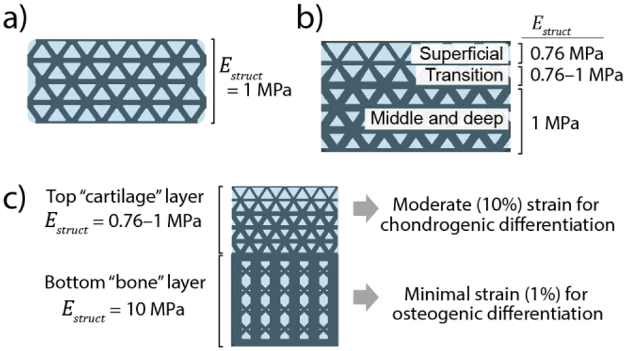
Design goals for 3D printed composite scaffolds; a) “uniform cartilage” structure with a uniform stiffness = 1 MPa; b) “gradient cartilage” structure featuring a gradient in stiffness to mimic the compressive strain patterns in native articular cartilage reported by Guilak et. [26]. c) “Osteochondral bilayer” structure combines the graded cartilage structure with a stiff bone layer to provide two distinct cellular environments
Our first design (“Uniform cartilage structure,” fig. 1.a) established a unit-cell based geometry that achieved uniform stiffness = 1 MPa throughout the structure. We selected a micro-truss geometry composed of octet-truss unit cells with high structural stiffness [38] which provided large spaces for infilling with hydrogel and cells. This design was chosen as a structurally efficient geometry that could maintain load-bearing ability at the high (10%) physiological strains applied to articular cartilage in vivo. Simple designs such as vertically oriented pillars that maximize structural efficiency (i.e., stiffness per volume ratio) were not used because of their susceptibility to buckle at high strains [4]. The octet-truss microstructure exhibits stretch-dominated deformation behavior to provide high structural efficiency, thus maximizing the volume available for a soft hydrogel infill while bending in the diagonal struts allowed for consistent deformation that avoids buckling and collapse at high (≥10%) strain [38]. Computer aided design software (Solidworks, Dassault Systèmes) was used to create unit cell geometries. All unit cells were sized 1.0×1.0 mm in x-y with 1.4 mm in z (height). Macrostructures (2.8 mm tall, 5.5 mm diameter cylinders) were then created by patterning unit cells and cutting out a cylindrical shape. To tune the stiffness, = 1 MPa, we used finite element modeling (FEM) to predict an empirical relationship between strut diameter and stiffness using previously determined material properties for the printed material used herein [61]. The final design featured 180 μm diameter struts. Methods for finite element modeling are described in section 2.2.
Our second design (“Gradient cartilage structure,” fig. 1.b) featured a spatially varying geometry to generate a controlled stiffness gradient and to produce a strain gradient mimicking native cartilage strain patterns during compression [51]. The resulting structure was two-and-a-half unit cells in height (3.5 mm) and 5.5 mm in diameter. Strut diameters varied from 180 μm to 160 μm to vary stiffness from 1 MPa (bottom) to 0.76 MPa (top) and were based on FEA predictions described in section 2.2. The “transition” region (fig. 1.b) featured conical geometries for the diagonal struts to transition from 180 μm diameter to 160 μm diameter.
Finally, our third design (“Osteochondral bilayer structure,” fig. 1.c) combined the “gradient cartilage” geometry with a ~10× stiffer bone-mimetic layer that was designed to minimize strains while maintaining ~25% volume of the solid, printed material. This latter design requirement was selected to maintain adequate space for an infilling hydrogel to support cells [53]. These designs were fabricated as single monolithic structures that were 7.6 mm tall and 5.5 mm in diameter. In the bone region, vertical pillars with interconnecting diagonal struts were used to maximize stiffness while maintaining suitable pore sizes (>100 μm) to enable bone ingrowth in future studies. Further details on the bilayer gradient structure design are provided in supplemental fig. 1.
2.2. Finite element modeling
Three-dimensional finite element (FE) models were created in Abaqus CAE (Dassault Systèmes) to predict and tune the regional stiffness of 3D printed structure designs (Fig. 2). In total, 10 models were created: six models of a single layer of unit cells were created with varying strut diameters to determine the relationship between stiffness and unit cell geometry (Fig. 2.a,b); a composite model of a single-layer of unit cells to investigate the infill mechanical environment (Fig. 2.c); and macro-structure models of the uniform cartilage (Fig. 2.d), gradient cartilage (Fig. 2.e), and osteochondral bilayer (Fig. 2.f) structures.
Fig. 2.

Finite element (FE) models: a) Side and top view of FE model for single-layer sub-model used to iteratively change strut diameter and to tune the resulting stiffness ; b) Predicted relationship between strut diameter-to-unit cell edge length ratio, , and stiffness, , fit with a 2nd order polynomial () which can be used to guide future designs using repeated octet-trusses. (c-f) side and top views of FE model meshes: c) infill composite sub-model; d) uniform cartilage; e) gradient cartilage; f) osteochondral bilayer. Dotted lines signify symmetric boundary conditions
For all models, a linear elastic material was considered for the 3D printed structure with an elastic modulus = 32 MPa and Poisson’s ratio, v, of 0.45 as determined previously [61]. Comparative models using neo-Hookean hyperelastic material formulations (with material constants derived from and v) found <1% difference in results, indicating that linear elastic material formulations adequately described material behavior in our models. Symmetry planes and boundary conditions were prescribed as shown in Fig. 2 to reduce computational expense. Unconfined compression was modeled by prescribing the movement of a rigid surface with frictionless contact prescribed between the surface and the top of structures. All structures were evaluated at 10% strain, except for the osteochondral bilayer which was evaluated to 4.5% total strain to achieve ~10% strain in the cartilage layer. Nonlinear geometric effects were considered during all simulations, using a “Static, general” step (Abaqus Standard). All meshes, except for the infill gel mesh (Fig. 2.c), used quadratic hybrid tetrahedral elements (C3D10H).
Outcome measures included the total force applied to the structure and the relative vertical displacement of selected nodes at evenly spaced points on the structure to characterize regional strains. Regional stiffness was calculated from regional strains, applied force (multiplied by four to represent the entire structure), and cross-sectional area of a circle circumscribing the model () (Fig. 2.a,b).
To tune the stiffness of our cellular structures, we varied strut diameter in a single-layer model (Fig. 2.a) to empirically determine a relationship between and strut diameter (normalized as the ratio of strut diameter to unit cell edge length, (Fig. 2.b). Comparative models that used multiple layers of unit cells in the vertical direction found that structural stiffness, , was insensitive (<1% change) to the height of the scaffolds; thus, single-layer models represented the macro-structure response of a uniform cellular structure. For final macro-structure models (i.e. uniform cartilage (Fig. 2.d), gradient cartilage (Fig. 2.e), and osteochondral bilayer (Fig. 2.f)), the full height of each structure was used.
To better understand the environment of an infilling gel in which cells can reside, we created an FE model of a single-layer structure bonded to a soft infilling gel. The infilled single-layer model (Fig. 2.c) featured a soft infill phase bonded to the stiff structure using tie constraints. The soft infill was modeled as linear elastic with = 25 kPa (previously determined) and Poisson’s ratio = 0.45 [53]. The soft infill mesh used 661k quadratic modified hybrid tetrahedral (C3D10MH) elements. Outputs for strain and stress were requested at each integration point along with each point’s integration volume; these values were printed to a text file and exported to Matlab (Mathworks) to generate density plots for the volumetric distributions of each measure.
Verification and validation of our finite element models included convergence studies on mesh density and comparisons to mechanical testing results. Mesh refinement studies predicted that our models had <0.1% discretization error. Mesh refinements were performed in the single-layer structure (Fig. 2.a) with the number of elements ranging 28–310k. The final meshes for the single layer sub-model (Fig. 2.a) contained approximately 80k hybrid quadratic tetrahedral (C3D10H) elements and featured at least three elements spanning the smallest feature sizes; subsequent simulations of macroscale structures used the same mesh density. Mesh refinements were performed independently on the osteochondral bilayer design and found similar agreement between results from fine and coarse meshes. The final osteochondral bilayer model used 767k C3D10H elements. No analytical solutions were available for large deformations of an octet truss space frame to compare against our models. Comparison between model and experimental results found 10% difference in force for the uniform cartilage structure but greater error for gradient cartilage and osteochondral bilayer designs. Sources of error between modeling and experiment are considered in the Discussion section. The final Abaqus model (.cae) files and output (.odb) files are provided in an online database [26].
2.3. 3D printed structure materials, fabrication, and iodine treatment
Structures were 3D printed using a custom microstereolithography (μSLA) printer and a resin (700 g/mol poly(ethylene glycol) diacrylate (PEGDA) with pentaerythritol tetrakis(3‐mercaptopropionate) (PETMP), diphenyl(2,4,6‐trimethylbenzoyl) phosphine oxide (photoinitiator), and Tinuvin® CarboProtect® (absorber), and 2,2′‐Azobis(2‐methylpropionitrile) (AIBN, thermal initiator)) as described in [61] (Fig. 3.a). For each structure, a computer-aided design (CAD) file was sliced into 25 μm thick layers to produce masks for printing. The 3D print files (.stl) are provided by the authors in an online database [26]. Each layer was exposed for 6 s using a 405 nm LED (Thorlabs Solis 405-C) at 30 mW/cm2. Following printing, structures were briefly rinsed in 100% ethanol to remove excess resin, then thermally post-cured at 100 °C for 1 hr (Fig. 3.b). After thermal post-cure, structures were rinsed with 100% ethanol for 24 hrs to remove photoinitiator, molecular absorber, and excess resin, and then allowed to air dry (Fig. 3.c). Structures were hydrated to equilibrium in phosphate buffered saline (PBS) prior to unconfined compression testing. Structures swelled by approximately 25% which was accounted for in CAD designs by applying a 0.8 scaling ratio prior to printing to achieve the desired final dimensions. Following mechanical testing, structures were then dehydrated to prepare for infilling with the soft gel pre-polymer solution. Before infilling with the hydrogel, printed structures were soaked in iodine to provide contrast for X-ray microscopy imaging of the composite structures (details in Supplementary Table 1).
Fig. 3.

Materials and fabrication methods. a) μSLA 3D printing using a 405 nm LED projected into monomer resin [61]. The chemical structures of the monomers and the resultant polymer network are shown; b) thermal post-cure to minimize layered gradients in conversion. c) Fabricated osteochondral bilayer structure after drying in air, with ballpoint pen in background for scale. d) Schematic for the infilling of the soft PEG hydrogel followed by photopolymerization to form composite as previously described [53, 54]. e) Photograph of an infilled scaffold without iodine stain f) photograph of an infilled scaffold stained with iodine stain.
2.4. Composite Fabrication
To investigate composite mechanical behavior of our 3D printed structures when filled with a soft scaffold material, we infilled structures with a previously established PEG hydrogel ( = 25 kPa) tissue engineering platform [53, 54]. The pre-polymer solution consisted of 9 wt% 8-arm PEG-norbornene (10 kDa), 1 kDa PEG-dithiol (1:1 thiol:ene ratio), and 0.05 wt% Irgacure 2959 (I2959), and was prepared as previously described [54] (Fig. 3.d). The precursor solution was injected directly into 3D printed structures in 10 μL increments allowing the solution to wick throughout the structure via capillary action. Once structures were completely infilled, they were photopolymerized with 352 nm light at 5 mW cm−2 for 8 minutes (Fig. 3.d). Following polymerization, the hydrogel composites were placed in PBS for a minimum of 48 hours to reach equilibrium swelling (increasing approximately 25% in volume) prior to testing.
2.4. Determining regional stiffness via unconfined compression and X-ray microscopy
To characterize the global stiffness of each structure, we performed unconfined compression using an MTS Insight II benchtop test frame (Fig. 4.c). Prior to testing, each sample’s diameter was measured using a USB digital microscope (Dino-lite). Compression was performed by prescribing ~12% strain to the structure at a rate of 1 mm/s. Global structural stiffness was calculated as the secant modulus between 5–10% global strain.
Fig. 4.

X-ray microscopy (XRM) was used in combination with mechanical testing to calculate regional stiffness. a) sample in the micrometer compression fixture, prepared for XRM imaging; b) initial (top) and compressed (bottom) images were used to measure regional strains and total strain; c) unconfined compression with the use of a load cell to measure force; d) force-displacement and stress-strain curve from unconfined compression, with approximate strain positions during XRM imaging overlayed.
In separate tests, X-ray microscopy (XRM) was used to visualize deformations in each structure during compression. The resulting images were used in combination with unconfined compression testing data to calculate regional stiffness. Imaging was performed with an Xradia Versa 520 (Carl Zeiss) using 80 kV voltage, 7W power, and a 4× objective. Voxel size ranged 5–6 μm. Imaging of empty structures without infill used 201 exposures with 0.5 s exposure time, while infilled structures required 2 s exposure times. Three-dimensional renderings of the XRM images were created in Dragonfly Pro (Object Research Systems) by isolating the 3D printed material through segmentation, meshing the resulting geometry, and smoothing the mesh. Because the soft infilling hydrogel and the 3D printed gel had the same X-ray absorbance, composite structures could only be visualized if stained in iodine prior to infilling with the soft gel (supplemental table 1). Renderings of the infilled composite structures were created by segmenting the iodine-stained 3D printed gel and infilling gel separately in Dragonfly Pro. Each phase was meshed and smoothed and the soft gel phase was visualized as translucent blue.
Structures were imaged in a compressed state using a custom-fabricated fixture and a micrometer with a non-rotating spindle to prescribe a vertical compression without inducing shear strain during deformation (Fig. 4.a). Initial (uncompressed) images were taken with the micrometer at the point of initial contact with the top of each structure, and final images were taken with a prescribed strain of 10% (or 4.5% for bilayer structures to achieve 10% strain in the cartilage layer). Due to compliance in the micrometer fixture, actual applied strains ranged 7–11% as measured in the TXM3DViewer software (Carl Zeiss, v1.2.10).
Outcome measures from XRM imaging were the total height of the structure and regional heights for initial and compressed configurations (Fig. 4.b). Three measurements were collected and averaged for each recorded height. From these initial and final heights, global and regional strains were calculated, which were later used in combination with unconfined compression data to characterize regional stiffness (Fig. 4.d). In this study, regional stiffness is reported instead of regional strain because global strains varied between samples due to compliance in the micrometer compression fixture. Images from XRM were also used to identify defects.
Regional stiffness values were determined by combining stress-strain data collected during unconfined compression testing and strain data measured via XRM imaging. By measuring global applied strain between initial and compressed configurations during XRM, we could then reference the stress-strain curve obtained in unconfined compression to assume an applied stress during XRM imaging of the deformed state (Fig. 4.d). We then divided the applied stress by each region’s local strain to calculate regional stiffness (or for composite structures). Deformation behavior was assumed to be the same during XRM imaging and unconfined compression testing. We also assumed the deformed positions of the structure did not change over time in the XRM compared to the relatively fast unconfined compression tests. Due to our small sample sizes, we chose not to perform statistical tests but rather presented all data points (regional and global stiffness) from each sample together along with the mean values from each sample group (Fig. 5, Fig. 7, Fig. 8).
Fig. 5.

Uniform cartilage structure results, showing the design and model predictions (a-d), the fabricated structure and its regional mechanics (n=5) (e-h), and the iodine-stained structure-infill composite and its regional mechanics (n=3) (i-l). e,i) Side images of the fabricated materials; f,j) renderings of the structure geometry (white) created from XRM images show the fabricated micro-truss network; the surrounding infill is visualized in blue in (j). g,k) Initial and final XRM images of the structure visualize deformation behavior under compression; h,l) calculated regional stiffness for the empty structure and infilled structure, respectively. m) Force-displacement curves from the FE model and experiments.
Fig. 7.

Gradient cartilage structure results, showing the design and model predictions (a-d), the fabricated empty structure and its regional mechanics (n=5) (e-h), and the iodine-stained structure-infill composite and its regional mechanics (n=3) (i-l). e,i) Side images of the fabricated materials; f,j) renderings of the structure geometry (white) created from XRM images show the fabricated micro-truss network; the surrounding infill is visualized in blue in (j). g,k) Initial and final XRM images of the structure visualize deformation behavior under compression. Note the fracture in a horizontal bar (arrow) and local buckling (asterisk, indicated by a slight twist at the node) that is visible in the right panel of (k); h,l) calculated regional stiffness for the empty structure and infilled structure, respectively. m) Force-displacement curves of the FE model compared to experiment.
Fig. 8.

Osteochondral bilayer cartilage structure results, showing the design and model predictions (a-d), the fabricated empty structure results (n=4) (e-h), and the iodine-stained structure-infill composite results (n=2) (i-l). e,i) Side images of fabricated structures; f,j) renderings of the structure geometry (white) created from XRM images show the fabricated micro-truss network; the surrounding infill is visualized in blue in (j). g,k) Initial and final XRM images of the structure visualize deformation behavior under compression. h,l) Calculated regional stiffness for the empty structure and infilled structure, respectively, including a calculation of the total cartilage stiffness (Cart. total). m) Force-displacement curves comparing the FE model to experiment
3. Results
3.1. Uniform cartilage design
The “uniform cartilage” structure design featured a strut diameter of 180 μm and 80% porosity (volume fraction = 0.20) (Fig. 5.a) with a pore spacing of 380 μm (supplemental fig. 2). Finite element modeling predicted a uniform stiffness of = 1.0 MPa throughout the structure (Fig. 5.c,d). Fabricated structures were photographed and imaged with X-ray microscopy (XRM) before and after unconfined compression testing (Fig. 5.e–g). Mean regional stiffness ranged 1.0–1.1 MPa (Fig. 5.h). Following infill with the soft hydrogel, imaging and testing were repeated; regional stiffness ranged 0.6–0.9 MPa in the composite scaffolds (Fig. 5.i–l). Force-displacement curves up to approximately 0.27 mm displacement (10% strain) were obtained and plotted alongside the FE-predicted response (Fig. 5.m) of the empty structure.
3.2. Mechanical environment within infilling gel
We predicted the mechanical environment of the infilling gel during compression using an FE sub-model of a single layer of unit cells bonded to the soft gel (Fig. 6). Mean compressive strain magnitudes in the gel scaffold were predicted to be 40% greater than global applied strain (Fig. 7.b). Strains within the gel also were variable and ranged from ~5% to ~25%. The highest predicted stresses and strains were located along the interface of the soft gel and diagonal struts (Fig. 6.b–d). Von Mises stress ranged 2 to 4.5 kPa (Fig. 6.c) while hydrostatic stress ranged 0.5 to 4.5 kPa and with the lowest pressures located at the perimeter of the gel (i.e., the edge of the sample).
Fig. 6.

Mechanical environment of the soft ( = 25 kPa) hydrogel when subjected to 10% global strain. a) Strain fields of the structure-infill composite visualized in 3D by reflecting all three symmetric boundary condition planes and applying a ‘view-cut’ to show cross-sections. b) Strain field of the soft infill (left) and volumetric distribution (right) show that typical strains in the infill exceed the prescribed global strain of −0.10. c) Von Mises stress field of the soft infill (left) and volumetric distribution (right). d) Hydrostatic stress field of the soft infill (left) and volumetric distribution (right).
3.3. Gradient cartilage design
A “gradient cartilage” structure featured varying strut diameters (Fig. 7.a) which were selected to achieve a gradient in stiffness ranging = 0.74–1 MPa according to the previously determined relationship between strut diameter and stiffness (Fig. 3.b). The gradient cartilage design had 81% porosity (volume fraction = 0.19) (Fig. 7.a) and a minimum pore size of 380 μm (supplemental fig. 2). Finite element models of the empty structure predicted a stiffness gradient ranging = 0.7–1.1 MPa (Fig. 5.c,d). 3D printed structures were photographed and imaged with XRM before and after compression (Fig. 5.e–g). Mean regional stiffness ranged 0.3–0.6 MPa (Fig. 5.h). Following infill with the soft hydrogel, imaging and testing were repeated; regional stiffness ranged 0.3–1.1 MPa in the composite scaffolds (Fig. 5.i–l). Force-displacement curves up to approximately 0.4 mm displacement (11% strain) were obtained and plotted alongside the FE-predicted response (Fig. 5.m).
3.4. Osteochondral bilayer design
The “osteochondral bilayer” structure combined the geometry of the gradient cartilage structure from section 3.1 with an underlying, 10× stiffer “bone” region of vertical pillars. FEM of the empty bilayer structure predicted a stiffness gradient ranging = 0.7–1.7 MPa in the cartilage region and = 9.3 MPa in the bone region (Fig. 8.c,d). The bone layer had 68% porosity (volume fraction = 0.32) (Fig.8.a) with 420 μm pore size (supplemental fig. 2). Fabricated structures were photographed (Fig. 8.e) and imaged (XRM) before and after compression (Fig. 8.f,g), and then mechanically tested to determine regional stiffness (Fig. 8.h). Following infill with the soft hydrogel, imaging and testing were repeated (Fig. 8.i–l). Force-displacement curves were obtained and plotted alongside the FE-predicted response (Fig. 8.m) and demonstrated moduli of ~1 MPa in the cartilage region with 5.8 MPa and 6.4 MPa in the empty and hydrogel-infilled structures, respectively.
4. Discussion
In this study, we fabricated composite hydrogel-infilled osteochondral microtruss scaffolds using microstereolithography (μSLA) printing with control over both overall and regional compressive stiffnesses. The composite scaffolds demonstrated the ability to bear physiological load levels while achieving strain patterns mimicking those within articular cartilage through spatial control of structure design. We also demonstrated a new approach to evaluate the in situ regional mechanics of empty and composite scaffolds by tracking sub-millimeter scale deformations during X-ray microscopy (XRM) imaging and unconfined compression. We further evaluated the mechanics of the infilling hydrogel, to describe the cellular-scale microenvironment in composite scaffolds, using finite element modeling (FEM). Taken together, we demonstrated an approach that enables greater control of the scaffold mechanical environment than existing 3D printing and other fabrication techniques. This work will support new advances in microscale-level design for gradient scaffolds using 3D printing and provides a basis for future mechanistic in vitro studies of cell mechanobiology and studies of implant performance.
A single layer, “uniform cartilage” design demonstrated the ability to achieve a target stiffness ( = 1 MPa) within the range of native cartilage equilibrium elastic moduli ( = 0.2–2 MPa) [37]. Existing composite scaffold approaches achieved and exceeded cartilage-level stiffness [10, 19, 27, 52, 62]. However, our approach is unique by applying a porous micro-truss geometry with greater stiffness-to-volume ratio than horizontally-oriented lattices, thus maximizing the volume available for cells and new tissue growth [53]. Our uniform cartilage design, which had a 5.5 mm diameter and 180 μm diameter struts, had a printed material volume fraction of 0.2. The remaining 80% of the total volume was available for an infilling hydrogel that could include cells to support tissue growth. Our approach also demonstrated control over stiffness magnitude; we targeted = 1 MPa, tuned our designs with FE modeling, and used μSLA-printing with stiff PEGDA formulations to reproduce fabricated structures within 10% of the desired stiffness (Figure 5.h).
Model predictions of the mechanical environment of an infilling gel determined that compressive strains were higher than the global applied strain, and that the stiff structure effectively shielded the infilling gel from high stresses. Mean compressive strain values extended from ~5% to ~25% under a 10% externally applied global strain. This discrepancy may be explained by the choice of scaffold geometry, which heavily influences scaffold mechanics [12], and the constraining effects of the stiff structure [40]. For a simple hydrogel in unconfined compression, the strain magnitudes would theoretically match the global prescribed strain [8]. However, adding the structure within the gel constrained the infill under compression which increased the maximum strain. This phenomenon is important to consider when attempting to deliver a specific dynamic strain for embedded cells. For example, an in vitro study on MSC differentiation within a PEG hydrogel scaffold found that 5–10% dynamic strains could support chondrogenesis [2]. Thus, if we embedded cells within our composite scaffolds in vitro, we could prescribe a 5% global strain to deliver 5–10% strain to cells. Other aspects of the mechanical environment, such as von Mises stress and hydrostatic pressure, may also affect chondrocyte and other cell fate [17]. The mean von Mises stress was 3.2 kPa; in contrast, if the same downward force (2.4 N) were applied to the gel without a reinforcing structure, the gel would experience 100 kPa von Mises stress which would result in extreme strain and likely material failure. While experimental measurement of 3D strains within the soft gel (e.g., [36]) would provide a valuable evaluation for the accuracy of this model, our approach demonstrated the importance of FEM-based characterization of strain environments in architected scaffolds.
Our second (“gradient cartilage”) and third (“osteochondral bilayer”) phases of design mimicked native strain gradients and demonstrated an XRM-based technique for evaluating regional stiffness on a sub-millimeter scale. Existing bilayer designs fabricated via extrusion printing have achieved separate “cartilage” and “bone” regions of varying stiffness to provide site-specific mechanical environments to encapsulated cells [39]. However, few studies have varied stiffness on a sub-millimeter level, e.g., within the zonal organization of articular cartilage [67] to provide region-specific mechanical cues to cells. We demonstrated a μSLA printing-based approach with the accuracy needed to prescribe gradients in geometry. Based on the relationship that we predicted between unit-cell geometry and resulting stiffness (Fig. 2.b), we observed that a mere 10% decrease in strut diameter would result in a predicted 25% decrease in stiffness; the sensitivity of stiffness to geometry therefore requires the use of a high-resolution printing system to effectively control stiffness. Furthermore, no studies have characterized the resulting regional stiffness within a composite scaffold. Hydrogels have a low density and are poorly visualized using X-ray based approaches, thus the use of contrast agents is necessary. A recent study by Bittner et al. used micro-computed tomography imaging to characterize regional strains in a tri-layer lattice structure; however, this study did not measure strains within an infilled composite nor did they characterize regional stiffness [12]. Our approach of combined XRM and unconfined compression with the use of iodine to provide contrast, as well as FEM to predict the mechanical environment within the infilling hydrogel, establishes a combined approach that enables the evaluation of the cellular microenvironment and verification of the ability to control regional strains.
By creating two distinct stiffness regions within a single structure, the osteochondral bilayer scaffold was designed to encourage chondrogenesis in the cartilage region with moderate (5–10%) compressive strains under 100 kPa loading while minimizing strains in the bone region to promote osteogenesis [8, 49]. The measured stiffness of the bone region in the osteochondral bilayer ( = 5.8–6.4 MPa) demonstrated the ability of μSLA printing to create regions of ~6× increase in stiffness within a single scaffold while maintaining 68% porosity and >400 m pore sizes adequate for bone ingrowth [13, 35, 60]. Existing extrusion-based 3D printed scaffolds can achieve greater stiffness of up to 400 MPa through the use of polyester composites [27, 29], while ceramic-based 3D printed scaffolds can approach the stiffness of subchondral bone (297–475 MPa) [24, 25]. Thus, the presented μSLA-printed osteochondral bilayer does not surpass other techniques in overall stiffness but does achieve 6× change in stiffness across a single structure. This single-part design eases fabrication and features a continuous structure between the cartilage and bone regions that may prevent delamination, a common problem for cartilage implants [34, 41, 48].
Although our approach used a photopolymerizable PEG hydrogel, the infilling soft phase can consist of any injectable hydrogel system that delivers and supports cells. While our composite scaffolds were non-degradable, we demonstrated success of MMP-sensitive degradable crosslinks within bone- and cartilage mimetic hydrogels [2, 3, 53, 54] and the ability to print fully degradable resin material [45]. When combined with emerging printing methods and the capability to print sub-millimeter features, composite scaffolds that include soft hydrogels enable both spatially directed mechanical and biochemical cues to cells. Specific geometries that fit patient-specific defects may also be printed, an advantage of additive manufacturing over bulk fabrication methods [32]. Other characteristics like porosity can further direct MSC differentiation [56]. Emerging techniques, e.g. volumetric additive manufacturing (VAM), will further facilitate fabrication of composite and cell-laden scaffolds due to the ability to rapidly form complex geometries and permit overprinting of new materials (e.g., hydrogel) in and around an existing printed structures [50]. Moreover, FEM demonstration of a heterogeneous strain field indicates that alternate structure designs (e.g., those with continuous boundaries like triply periodic minimal surface (TPMS) [65]) may be desired to facilitate a more homogenous strain environment within infilling hydrogels.
Our study has several limitations. While the “uniform cartilage” structure achieved a stiffness within 10% of the target = 1 MPa, the “cartilage gradient” structure and the bony layer in the osteochondral scaffold were softer than expected. XRM measurements of printed geometries revealed that the “cartilage gradient” structures’ diagonal struts were 10% smaller in diameter than designed. Structural stiffness was highly sensitive to the strut diameter. The regional stiffness also did not follow predictions after infilling with the soft gel. We posit that the infilling gel, while being ~1000× softer than the stiff material, was incompressible and added lateral pressure to the struts during compression and thus contributed to local buckling phenomena (fig. 7.k) thus resulting in variability in regional deformation behavior. Evidence of buckling was observed in the “uniform cartilage” composite scaffold’s force-displacement curve, indicated by the decrease in slope (i.e. stiffness) at high displacements (Figure 5.m). Our FE model assumed perfect bonding between the soft and stiff phases, which was not experimentally verified. Also, the assumption of Poisson’s ratio = 0.45 did not describe an incompressible hydrogel ( = 0.5) which likely reduced stress and strain magnitudes reported by our models. Mechanical behavior during XRM imaging did not account for viscous effects and elevated temperatures generated during scanning which may have contributed to differences between estimated stiffness and results from compression experiments in our mechanical testing system. Our study only considered unconfined compression response, while implants in vivo also will inevitably experience shear loading. Although not tested or modeled, we expect the octet-truss design to be relatively stiff under shear loading due to the diagonal orientation of struts. A previous study showed that octet-truss geometries were effective in resisting shear stresses and were stable in any direction of shear loading [22].
In conclusion, this study demonstrated 3D printed composite scaffolds with layered designs that control regional stiffness for osteochondral tissue regeneration. XRM-based measurements of regional deformation enabled the evaluation of stiffness gradients under compression. As an implant, our osteochondral bilayer scaffold design may have the ability to direct osteochondral tissue regeneration while bracing surrounding cartilage from excessive loads to prevent further tissue degradation and enable lateral integration. In addition, we recently demonstrated the ability to print with a custom, degradable material using μSLA which offers exciting potential to implant fully resorbable microtruss scaffolds [45]. In summary, this combined approach offers future implant designs with improved control of regional mechanics and better scaffold performance for osteochondral tissue regeneration.
Supplementary Material
Acknowledgements
This work was supported with funding from NIH R21/R33 HD090696, R01 AR069060, and the University of Colorado Gates Grubstake Fund. X-ray microscopy and unconfined compression testing was performed at MIMIC, CU Boulder (RRID: SCR_019307).
Authors would like to thank Karl Johannes for fabricating the X-ray microscopy micrometer compression fixture.
Footnotes
CRediT authorship contribution statement
Kevin N. Eckstein: Conceptualization, Methodology, Software, Validation, Formal analysis, Investigation, Writing – Original Draft, Visualization. John E. Hergert: Methodology, Resources, Writing – Review & Editing. A. Camila Uzcategui: Methodology, Resources, Writing – Review & Editing. Sarah A. Schoonraad: Methodology, resources, Writing – Review & Editing. Stephanie J. Bryant: Conceptualization, Resources, Writing – Review & Editing, Supervision, Project administration, Funding acquisition. Robert R. McLeod: Conceptualization, Methodology, Supervision, Project administration, Resources, Writing – Review & Editing, Funding acquisition. Virginia L. Ferguson: Conceptualization, Methodology, Resources, Writing – Review & Editing Supervision, Project administration, Funding acquisition.
Statements and Declarations
The authors declare that they have no known competing financial interests or personal relationships that could have appeared to influence the work reported in this paper.
References
- 1.Abaci A, Guvendiren M (2020) Designing Decellularized Extracellular Matrix-Based Bioinks for 3D Bioprinting. Advanced Healthcare Materials 9:2000734. doi: 10.1002/adhm.202000734 [DOI] [PubMed] [Google Scholar]
- 2.Aisenbrey EA, Bryant SJ (2016) Mechanical loading inhibits hypertrophy in chondrogenically differentiating hMSCs within a biomimetic hydrogel. J Mater Chem B Mater Biol Med 4:3562–3574. doi: 10.1039/c6tb00006a [DOI] [PMC free article] [PubMed] [Google Scholar]
- 3.Aisenbrey EA, Bryant SJ (2018) A MMP7-sensitive photoclickable biomimetic hydrogel for MSC encapsulation towards engineering human cartilage. J Biomed Mater Res A 106:2344–2355. doi: 10.1002/jbm.a.36412 [DOI] [PMC free article] [PubMed] [Google Scholar]
- 4.Aisenbrey EA, Tomaschke A, Kleinjan E, Muralidharan A, Pascual-Garrido C, McLeod RR, Ferguson VL, Bryant SJ (2018) A Stereolithography-Based 3D Printed Hybrid Scaffold for In Situ Cartilage Defect Repair. Macromolecular Bioscience. doi: 10.1002/mabi.201700267 [DOI] [PMC free article] [PubMed] [Google Scholar]
- 5.Aisenbrey EA, Tomaschke AA, Schoonraad SA, Fischenich KM, Wahlquist JA, Randolph MA, Ferguson VL, Bryant SJ (2019) Assessment and prevention of cartilage degeneration surrounding a focal chondral defect in the porcine model. Biochem Biophys Res Commun 514:940–945. doi: 10.1016/j.bbrc.2019.05.034 [DOI] [PMC free article] [PubMed] [Google Scholar]
- 6.Allen KD, Thoma LM, Golightly YM (2022) Epidemiology of osteoarthritis. Osteoarthritis and Cartilage 30:184–195. doi: 10.1016/j.joca.2021.04.020 [DOI] [PMC free article] [PubMed] [Google Scholar]
- 7.Arcaute K, Mann BK, Wicker RB (2006) Stereolithography of Three-Dimensional Bioactive Poly(Ethylene Glycol) Constructs with Encapsulated Cells. Ann Biomed Eng 34:1429–1441. doi: 10.1007/s10439-006-9156-y [DOI] [PubMed] [Google Scholar]
- 8.Aziz AH, Eckstein K, Ferguson VL, Bryant SJ (2019) The effects of dynamic compressive loading on human mesenchymal stem cell osteogenesis in the stiff layer of a bilayer hydrogel. Journal of Tissue Engineering and Regenerative Medicine 13:946–959. doi: 10.1002/term.2827 [DOI] [PMC free article] [PubMed] [Google Scholar]
- 9.Bartell LR, Fortier LA, Bonassar LJ, Cohen I (2015) Measuring microscale strain fields in articular cartilage during rapid impact reveals thresholds for chondrocyte death and a protective role for the superficial layer. J Biomech 48:3440–3446. doi: 10.1016/j.jbiomech.2015.05.035 [DOI] [PMC free article] [PubMed] [Google Scholar]
- 10.Beck EC, Barragan M, Tadros MH, Gehrke SH, Detamore MS (2016) Approaching the compressive modulus of articular cartilage with a decellularized cartilage-based hydrogel. Acta Biomater 38:94–105. doi: 10.1016/j.actbio.2016.04.019 [DOI] [PMC free article] [PubMed] [Google Scholar]
- 11.Bennett J (2017) Measuring UV Curing Parameters of Commercial Photopolymers used in Additive Manufacturing. Addit Manuf 18:203–212. doi: 10.1016/j.addma.2017.10.009 [DOI] [PMC free article] [PubMed] [Google Scholar]
- 12.Bittner SM, Smith BT, Diaz-Gomez L, Hudgins CD, Melchiorri AJ, Scott DW, Fisher JP, Mikos AG (2019) Fabrication and mechanical characterization of 3D printed vertical uniform and gradient scaffolds for bone and osteochondral tissue engineering. Acta Biomaterialia 90:37–48. doi: 10.1016/j.actbio.2019.03.041 [DOI] [PMC free article] [PubMed] [Google Scholar]
- 13.Bobyn JD, Pilliar RM, Cameron HU, Weatherly GC (1980) The optimum pore size for the fixation of porous-surfaced metal implants by the ingrowth of bone. Clin Orthop Relat Res 263–270 [PubMed] [Google Scholar]
- 14.Bracaglia LG, Smith BT, Watson E, Arumugasaamy N, Mikos AG, Fisher JP (2017) 3D printing for the design and fabrication of polymer-based gradient scaffolds. Acta Biomater 56:3–13. doi: 10.1016/j.actbio.2017.03.030 [DOI] [PMC free article] [PubMed] [Google Scholar]
- 15.Bryant SJ, Anseth KS (2002) Hydrogel properties influence ECM production by chondrocytes photoencapsulated in poly(ethylene glycol) hydrogels. J Biomed Mater Res 59:63–72. doi: 10.1002/jbm.1217 [DOI] [PubMed] [Google Scholar]
- 16.Burdis R, Chariyev-Prinz F, Kelly DJ (2021) Bioprinting of biomimetic self-organised cartilage with a supporting joint fixation device. Biofabrication 14. doi: 10.1088/1758-5090/ac36be [DOI] [PubMed] [Google Scholar]
- 17.Carter DR, Beaupré GS, Wong M, Smith RL, Andriacchi TP, Schurman DJ (2004) The Mechanobiology of Articular Cartilage Development and Degeneration. Clinical Orthopaedics and Related Research® 427:S69. doi: 10.1097/01.blo.0000144970.05107.7e [DOI] [PubMed] [Google Scholar]
- 18.Chu TC, Ranson WF, Sutton MA (1985) Applications of digital-image-correlation techniques to experimental mechanics. Experimental Mechanics 25:232–244. doi: 10.1007/BF02325092 [DOI] [Google Scholar]
- 19.Critchley S, Sheehy EJ, Cunniffe G, Diaz-Payno P, Carroll SF, Jeon O, Alsberg E, Brama PAJ, Kelly DJ (2020) 3D printing of fibre-reinforced cartilaginous templates for the regeneration of osteochondral defects. Acta Biomater 113:130–143. doi: 10.1016/j.actbio.2020.05.040 [DOI] [PubMed] [Google Scholar]
- 20.Daly AC, Freeman FE, Gonzalez-Fernandez T, Critchley SE, Nulty J, Kelly DJ (2017) 3D Bioprinting for Cartilage and Osteochondral Tissue Engineering. Adv Healthc Mater 6. doi: 10.1002/adhm.201700298 [DOI] [PubMed] [Google Scholar]
- 21.Daly AC, Kelly DJ (2019) Biofabrication of spatially organised tissues by directing the growth of cellular spheroids within 3D printed polymeric microchambers. Biomaterials 197:194–206. doi: 10.1016/j.biomaterials.2018.12.028 [DOI] [PubMed] [Google Scholar]
- 22.Deshpande VS, Fleck NA, Ashby MF (2001) Effective properties of the octet-truss lattice material. Journal of the Mechanics and Physics of Solids 49:1747–1769. doi: 10.1016/S0022-5096(01)00010-2 [DOI] [Google Scholar]
- 23.Diaz-Rodriguez P, Erndt-Marino JD, Gharat T, Munoz Pinto DJ, Samavedi S, Bearden R, Grunlan MA, Saunders WB, Hahn MS (2019) Toward zonally tailored scaffolds for osteochondral differentiation of synovial mesenchymal stem cells. Journal of Biomedical Materials Research Part B: Applied Biomaterials 107:2019–2029. doi: 10.1002/jbm.b.34293 [DOI] [PMC free article] [PubMed] [Google Scholar]
- 24.Ding M, Danielsen CC, Hvid I (2001) Bone density does not reflect mechanical properties in early-stage arthrosis. Acta Orthopaedica Scandinavica 72:181–185. doi: 10.1080/000164701317323444 [DOI] [PubMed] [Google Scholar]
- 25.Doyle SE, Snow F, Duchi S, O’Connell CD, Onofrillo C, Di Bella C, Pirogova E (2021) 3D Printed Multiphasic Scaffolds for Osteochondral Repair: Challenges and Opportunities. International Journal of Molecular Sciences 22:12420. doi: 10.3390/ijms222212420 [DOI] [PMC free article] [PubMed] [Google Scholar]
- 26.Eckstein KN (2024) Micro-truss models for 3D printed scaffold reinforcements. OSF. available at https://osf.io/J93DB/ doi: 10.17605/OSF.IO/J93DB [DOI] [Google Scholar]
- 27.Ege D, Hasirci V (2023) Is 3D Printing Promising for Osteochondral Tissue Regeneration? ACS Appl Bio Mater 6:1431–1444. doi: 10.1021/acsabm.3c00093 [DOI] [PMC free article] [PubMed] [Google Scholar]
- 28.Erickson AE, Sun J, Lan Levengood SK, Swanson S, Chang F-C, Tsao CT, Zhang M (2019) Chitosan-based composite bilayer scaffold as an in vitro osteochondral defect regeneration model. Biomed Microdevices 21:34. doi: 10.1007/s10544-019-0373-1 [DOI] [PubMed] [Google Scholar]
- 29.Golebiowska AA, Nukavarapu SP (2022) Bio-inspired zonal-structured matrices for bone-cartilage interface engineering. Biofabrication 14:025016. doi: 10.1088/1758-5090/ac5413 [DOI] [PubMed] [Google Scholar]
- 30.Griffin DJ, Bonnevie ED, Lachowsky DJ, Hart JCA, Sparks HD, Moran N, Matthews G, Nixon AJ, Cohen I, Bonassar LJ (2015) Mechanical characterization of matrix-induced autologous chondrocyte implantation (MACI®) grafts in an equine model at 53 weeks. J Biomech 48:1944–1949. doi: 10.1016/j.jbiomech.2015.04.010 [DOI] [PubMed] [Google Scholar]
- 31.Guilak F, Ratcliffe A, Mow VC (1995) Chondrocyte deformation and local tissue strain in articular cartilage: a confocal microscopy study. J Orthop Res 13:410–421. doi: 10.1002/jor.1100130315 [DOI] [PubMed] [Google Scholar]
- 32.Guo T, Lembong J, Zhang LG, Fisher JP (2017) Three-Dimensional Printing Articular Cartilage: Recapitulating the Complexity of Native Tissue. Tissue Eng Part B Rev 23:225–236. doi: 10.1089/ten.TEB.2016.0316 [DOI] [PubMed] [Google Scholar]
- 33.Hanke MS, Keel MJB, Cullmann JL, Siebenrock KA, Bastian JD (2020) Transfer of osteochondral shell autografts to salvage femoral head impaction injuries in hip trauma patients. Injury 51:711–718. doi: 10.1016/j.injury.2020.01.037 [DOI] [PubMed] [Google Scholar]
- 34.Huey DJ, Hu JC, Athanasiou KA (2012) Unlike Bone, Cartilage Regeneration Remains Elusive. Science 338:917–921. doi: 10.1126/science.1222454 [DOI] [PMC free article] [PubMed] [Google Scholar]
- 35.Itälä AI, Ylänen HO, Ekholm C, Karlsson KH, Aro HT (2001) Pore diameter of more than 100 μm is not requisite for bone ingrowth in rabbits. Journal of Biomedical Materials Research 58:679–683. doi: 10.1002/jbm.1069 [DOI] [PubMed] [Google Scholar]
- 36.Johannes KG, Calahan KN, Qi Y, Long R, Rentschler ME (2019) Three-Dimensional Microscale Imaging and Measurement of Soft Material Contact Interfaces under Quasi-Static Normal Indentation and Shear. Langmuir 35:10725–10733. doi: 10.1021/acs.langmuir.9b00830 [DOI] [PubMed] [Google Scholar]
- 37.Jurvelin JS, Buschmann MD, Hunziker EB (1997) Optical and mechanical determination of Poisson’s ratio of adult bovine humeral articular cartilage. J Biomech 30:235–241. doi: 10.1016/s0021-9290(96)00133-9 [DOI] [PubMed] [Google Scholar]
- 38.Kaur M, Yun TG, Han SM, Thomas EL, Kim WS (2017) 3D printed stretching-dominated micro-trusses. Materials & Design 134:272–280. doi: 10.1016/j.matdes.2017.08.061 [DOI] [Google Scholar]
- 39.Kilian D, Ahlfeld T, Akkineni AR, Bernhardt A, Gelinsky M, Lode A (2020) 3D Bioprinting of osteochondral tissue substitutes - in vitro-chondrogenesis in multi-layered mineralized constructs. Sci Rep 10:8277. doi: 10.1038/s41598-020-65050-9 [DOI] [PMC free article] [PubMed] [Google Scholar]
- 40.Kinneberg KRC, Nelson A, Stender ME, Aziz AH, Mozdzen LC, Harley BAC, Bryant SJ, Ferguson VL (2015) Reinforcement of Mono- and Bi-layer Poly(Ethylene Glycol) Hydrogels with a Fibrous Collagen Scaffold. Ann Biomed Eng 43:2618–2629. doi: 10.1007/s10439-015-1337-0 [DOI] [PMC free article] [PubMed] [Google Scholar]
- 41.Li C, Zhang W, Nie Y, Jiang D, Jia J, Zhang W, Li L, Yao Z, Qin L, Lai Y (2023) Integrated and Bifunctional Bilayer 3D Printing Scaffold for Osteochondral Defect Repair. Advanced Functional Materials 33:2214158. doi: 10.1002/adfm.202214158 [DOI] [Google Scholar]
- 42.Little CJ, Bawolin NK, Chen X (2011) Mechanical properties of natural cartilage and tissue-engineered constructs. Tissue Eng Part B Rev 17:213–227. doi: 10.1089/ten.TEB.2010.0572 [DOI] [PubMed] [Google Scholar]
- 43.Middendorf JM, Griffin DJ, Shortkroff S, Dugopolski C, Kennedy S, Siemiatkoski J, Cohen I, Bonassar LJ (2017) Mechanical properties and structure-function relationships of human chondrocyte-seeded cartilage constructs after in vitro culture. J Orthop Res 35:2298–2306. doi: 10.1002/jor.23535 [DOI] [PubMed] [Google Scholar]
- 44.Moutos FT, Guilak F (2008) Composite scaffolds for cartilage tissue engineering. Biorheology 45:501–512 [PMC free article] [PubMed] [Google Scholar]
- 45.Muralidharan A, McLeod RR, Bryant SJ (2022) Hydrolytically Degradable Poly(β‐amino ester) Resins with Tunable Degradation for 3D Printing by Projection Micro‐Stereolithography. Advanced Functional Materials 32:2106509. doi: 10.1002/adfm.202106509 [DOI] [PMC free article] [PubMed] [Google Scholar]
- 46.Murphy L, Helmick CG (2012) The impact of osteoarthritis in the United States: a population-health perspective: A population-based review of the fourth most common cause of hospitalization in U.S. adults. Orthop Nurs 31:85–91. doi: 10.1097/NOR.0b013e31824fcd42 [DOI] [PubMed] [Google Scholar]
- 47.Nicodemus GD, Bryant SJ (2008) The role of hydrogel structure and dynamic loading on chondrocyte gene expression and matrix formation. Journal of Biomechanics 41:1528–1536. doi: 10.1016/j.jbiomech.2008.02.034 [DOI] [PMC free article] [PubMed] [Google Scholar]
- 48.Niemeyer P, Pestka JM, Kreuz PC, Erggelet C, Schmal H, Suedkamp NP, Steinwachs M (2008) Characteristic complications after autologous chondrocyte implantation for cartilage defects of the knee joint. Am J Sports Med 36:2091–2099. doi: 10.1177/0363546508322131 [DOI] [PubMed] [Google Scholar]
- 49.Prendergast PJ, Huiskes R, Søballe K (1997) Biophysical stimuli on cells during tissue differentiation at implant interfaces. Journal of Biomechanics 30:539–548. doi: 10.1016/S0021-9290(96)00140-6 [DOI] [PubMed] [Google Scholar]
- 50.Rackson CM, Champley KM, Toombs JT, Fong EJ, Bansal V, Taylor HK, Shusteff M, McLeod RR (2021) Object-space optimization of tomographic reconstructions for additive manufacturing. Additive Manufacturing 48:102367. doi: 10.1016/j.addma.2021.102367 [DOI] [PMC free article] [PubMed] [Google Scholar]
- 51.Schinagl RM, Gurskis D, Chen AC, Sah RL (1997) Depth-dependent confined compression modulus of full-thickness bovine articular cartilage. J Orthop Res 15:499–506. doi: 10.1002/jor.1100150404 [DOI] [PubMed] [Google Scholar]
- 52.Schipani R, Scheurer S, Florentin R, Critchley SE, Kelly DJ (2020) Reinforcing interpenetrating network hydrogels with 3D printed polymer networks to engineer cartilage mimetic composites. Biofabrication 12:035011. doi: 10.1088/1758-5090/ab8708 [DOI] [PubMed] [Google Scholar]
- 53.Schoonraad SA, Fischenich KM, Eckstein KN, Crespo-Cuevas V, Savard LM, Muralidharan A, Tomaschke AA, Uzcategui AC, Randolph MA, McLeod RR, Ferguson VL, Bryant SJ (2021) Biomimetic and mechanically supportive 3D printed scaffolds for cartilage and osteochondral tissue engineering using photopolymers and digital light processing. Biofabrication 13:044106. doi: 10.1088/1758-5090/ac23ab [DOI] [PubMed] [Google Scholar]
- 54.Schoonraad SA, Trombold ML, Bryant SJ (2021) The Effects of Stably Tethered BMP-2 on MC3T3-E1 Preosteoblasts Encapsulated in a PEG Hydrogel. Biomacromolecules 22:1065–1079. doi: 10.1021/acs.biomac.0c01085 [DOI] [PMC free article] [PubMed] [Google Scholar]
- 55.Singh JA, Yu S, Chen L, Cleveland JD (2019) Rates of Total Joint Replacement in the United States: Future Projections to 2020–2040 Using the National Inpatient Sample. J Rheumatol 46:1134–1140. doi: 10.3899/jrheum.170990 [DOI] [PubMed] [Google Scholar]
- 56.Smith BT, Bittner SM, Watson E, Smoak MM, Diaz-Gomez L, Molina ER, Kim YS, Hudgins CD, Melchiorri AJ, Scott DW, Grande-Allen KJ, Yoo JJ, Atala A, Fisher JP, Mikos AG (2020) Multimaterial Dual Gradient Three-Dimensional Printing for Osteogenic Differentiation and Spatial Segregation. Tissue Eng Part A 26:239–252. doi: 10.1089/ten.TEA.2019.0204 [DOI] [PMC free article] [PubMed] [Google Scholar]
- 57.Steinmetz NJ, Aisenbrey EA, Westbrook KK, Qi HJ, Bryant SJ (2015) Mechanical loading regulates human MSC differentiation in a multi-layer hydrogel for osteochondral tissue engineering. Acta Biomater 21:142–153. doi: 10.1016/j.actbio.2015.04.015 [DOI] [PubMed] [Google Scholar]
- 58.Stender ME, Regueiro RA, Ferguson VL (2017) A poroelastic finite element model of the bone–cartilage unit to determine the effects of changes in permeability with osteoarthritis. Computer Methods in Biomechanics and Biomedical Engineering 20. doi: 10.1080/10255842.2016.1233326 [DOI] [PubMed] [Google Scholar]
- 59.Taboas JM, Maddox RD, Krebsbach PH, Hollister SJ (2003) Indirect solid free form fabrication of local and global porous, biomimetic and composite 3D polymer-ceramic scaffolds. Biomaterials 24:181–194. doi: 10.1016/s0142-9612(02)00276-4 [DOI] [PubMed] [Google Scholar]
- 60.Taniguchi N, Fujibayashi S, Takemoto M, Sasaki K, Otsuki B, Nakamura T, Matsushita T, Kokubo T, Matsuda S (2016) Effect of pore size on bone ingrowth into porous titanium implants fabricated by additive manufacturing: An in vivo experiment. Materials Science and Engineering: C 59:690–701. doi: 10.1016/j.msec.2015.10.069 [DOI] [PubMed] [Google Scholar]
- 61.Uzcategui AC, Muralidharan A, Ferguson VL, Bryant SJ, McLeod RR (2018) Understanding and Improving Mechanical Properties in 3D printed Parts Using a Dual-Cure Acrylate-Based Resin for Stereolithography. Advanced Engineering Materials 20:1800876. doi: 10.1002/adem.201800876 [DOI] [PMC free article] [PubMed] [Google Scholar]
- 62.Wang C, Yue H, Huang W, Lin X, Xie X, He Z, He X, Liu S, Bai L, Lu B, Wei Y, Wang M (2020) Cryogenic 3D printing of heterogeneous scaffolds with gradient mechanical strengths and spatial delivery of osteogenic peptide/TGF-β1 for osteochondral tissue regeneration. Biofabrication 12:025030. doi: 10.1088/1758-5090/ab7ab5 [DOI] [PubMed] [Google Scholar]
- 63.Wilmoth RL, Ferguson VL, Bryant SJ (2020) A 3D, Dynamically Loaded Hydrogel Model of the Osteochondral Unit to Study Osteocyte Mechanobiology. Advanced Healthcare Materials 9:2001226. doi: 10.1002/adhm.202001226 [DOI] [PMC free article] [PubMed] [Google Scholar]
- 64.Xu T, Zhao W, Zhu J-M, Albanna MZ, Yoo JJ, Atala A (2013) Complex heterogeneous tissue constructs containing multiple cell types prepared by inkjet printing technology. Biomaterials 34:130–139. doi: 10.1016/j.biomaterials.2012.09.035 [DOI] [PubMed] [Google Scholar]
- 65.Yang L, Li Y, Wu S, Chen P, Wu H, Su J, Wang H, Liu J, Yan C, Shi Y (2022) Tailorable and predictable mechanical responses of additive manufactured TPMS lattices with graded structures. Materials Science and Engineering: A 843:143109. doi: 10.1016/j.msea.2022.143109 [DOI] [Google Scholar]
- 66.Yodmuang S, McNamara SL, Nover AB, Mandal BB, Agarwal M, Kelly T-AN, Chao PG, Hung C, Kaplan DL, Vunjak-Novakovic G (2015) Silk microfiber-reinforced silk hydrogel composites for functional cartilage tissue repair. Acta Biomater 11:27–36. doi: 10.1016/j.actbio.2014.09.032 [DOI] [PMC free article] [PubMed] [Google Scholar]
- 67.Zhu D, Trinh P, Liu E, Yang F (2018) Biochemical and Mechanical Gradients Synergize To Enhance Cartilage Zonal Organization in 3D. ACS Biomater Sci Eng 4:3561–3569. doi: 10.1021/acsbiomaterials.8b00775 [DOI] [PMC free article] [PubMed] [Google Scholar]
Associated Data
This section collects any data citations, data availability statements, or supplementary materials included in this article.