

Abstract
In this paper, we demonstrate a synthesis of mesoporous carbon spheres via a self-assembly of resorcinol-formaldehyde polymer and surfactant F127 in aqueous phase in the presence of phytic acid as the catalyst and phosphorus source. The obtained mesoporous carbon spheres have high phosphorus content and excellent electrochemical performance. The enhancement of the electrochemical performance of the material is primarily attributed to the structural characteristics and chemical properties of phosphorus atoms being similar to those of nitrogen atoms, and the atomic radius being slightly larger than that of nitrogen atoms, with strong electron donating ability. After successful doping, rich active sites are formed. These carbon spheres are examined as electrode materials for supercapacitors. The structural characterization revealed that the mesoporous carbon spheres possessed an average pore diameter of 2.4 nm and a specific surface area of 1207 m2 g− 1. Electrochemical measurements demonstrated a specific capacitance of 257.5 F g− 1 at 0.5 A g− 1 in a three-electrode configuration. used as supercapacitor electrodes with a capacitance of 92.8 F g− 1 at a current density of 0.5 A g− 1. Furthermore, the energy density is 4.64 Wh Kg− 1 at a power density of 150 W Kg− 1 and the capacitance retention rate is 98.99% After 5000 cycles at a current density of 2 A g− 1, an extremely highly promising supercapacitor electrode material.
Keywords: Carbon spheres, Doping of heteroatoms, Soft template method, Electrode materials, Supercapacitor
Subject terms: Chemistry, Materials science
Introduction
The controlled utilization of energy plays a pivotal role in addressing the energy crisis, especially amidst optimizing energy structure transition. The controllability and storability of energy have emerged as the core driving forces behind energy technology innovation. There is a growing demand for advanced energy storage technologies as the proportion of clean energy sources increases and the power market undergoes profound changes. Among these technologies, supercapacitors, as efficient energy storage solutions, exhibit vast application prospects in energy management1–6. Notably, the electrode materials of supercapacitors directly influence their energy storage performance, emphasizing the significance of researching high-performance electrode materials7–10.
Metal sulfides11,12, metal oxides8,10,13–15, conductive polymers16,17, MXene9,18,19, metal-organic frameworks and covalent organic frameworks20,21, carbon materials22–24, etc. are currently the primary electrode materials used in supercapacitors. Mesoporous carbon materials have become a focus for carbon material researchers due to their narrow pore size distribution, high specific surface area, and large pores25. According to previous studies, most unmodified carbon materials have high hydrophobicity, which limits their practical applications. Thus many effects have been made to improve the surface properties of the carbon materials26. It has been confirmed that the incorporation of heteroatoms (such as B, N, P, and S) improves materials’ electrochemical performance significantly by increasing charge density, surface defects and hydrophilicity, and by decreasing charge transfer resistance27–30,32. Phosphorus atoms have attracted considerable attention as a dopant heteroatom due to their relatively large atomic radius and strong electron-donating capability. The introduction of phosphorus atoms into carbon materials can significantly enhance their catalytic performance, adsorption capacity, and charge storage properties, primarily attributed to the following mechanisms: Firstly, the lone pair electrons (3s²3p³) of phosphorus hybridize with the π-electron system of carbon, forming electron-rich regions that facilitate charge transfer in redox reactions31. Secondly, phosphorus doping creates vacancies and edge defects that serve as adsorption centers for molecules (e.g., H₂O, O₂) or ions (e.g., Li⁺, Na⁺). The larger atomic radius of phosphorus (107 pm) compared to carbon (77 pm) induces local lattice distortion, thereby activating adjacent carbon atoms32. Moreover, the phosphorus-induced hydrophilicity promotes electrolyte penetration, making it particularly suitable for energy storage devices such as supercapacitors33,34. Rong et al. used Phytic acid as a phosphorus source, and ZIF-8 as a hard template to synthesize phosphorus-doped mesoporous materials for oxygen reduction reaction (ORR)35. Zhang et al. used phytic acid as a P dopant, and polystyrene spheres as a template to synthesize an N/P dual-doped catalyst with excellent performance for redox reactions (ORR)36. Yang et al. used platelet-ordered mesoporous silica as a hard template, and triphenylphosphine as a P dopant to synthesize phosphorus-doped mesoporous materials for oxygen reduction reaction with superior long-term stability and excellent methanol tolerance33. Gustavo et al. used nano-SiO2 as a hard template, and sucrose as a carbon source to synthesize an adsorbent for adsorbing propranolol37. Huang et al. used phosphoric acid as a phosphorus dopant, cabbage waste as a carbon source to synthesize an adsorbent for adsorbing chloramphenicol (CHL), tetracycline (TC), ofloxacin (OFX) and erythromycin (ERY)38. Gong et al. used phosphoric acid as a phosphorus dopant, high-temperature calcination of waste tires to synthesize phosphorus-doped mesoporous materials for Anode materials39. Qu et al. used H3PO4 as a phosphorus source and activator, and rice husks as a carbon source to synthesize N/P dual-doped mesoporous materials for High Performance Supercapacitors40.
In this work, we report a facile one-step soft-templating method to directly synthesize P-doped mesoporous carbon spheres using polyether F127 and phytic acid as the porogen and phosphorus source, respectively. The obtained A-PMCs-2 possesses a high surface area (1207 m2 g− 1) and high P content (up to 8.56 wt%). Due to the high P content and hierarchical pore size distribution, A-PMCs-2 exhibits excellent performance as a supercapacitor electrode, with a specific capacitance of 186.4 F g− 1 at a current density of 0.5 A g− 1 (The electrolyte used in the experiment is 6 M KOH).
Experimental
All chemicals are used directly after purchase without undergoing secondary purification. Deionized water was used for the entire experimental process, including the cleaning of experimental vessels.
Synthesis of P-doped mesoporous carbon
In a typical synthesis, 1.25 g polyvinyl alcohol, 1.25 g sodium hydroxymethyl cellulose, and 35 ml deionized water in a round bottom flask, stirred continuously at 75 °C for 30 min to form a hydrogel solution. Then 2 mL phytic acid and 2.5 g resorcinol were dissolved in 10 mL deionized water, and the dissolved mixture was added dropwise to the hydrogel solution and stirred for 15 min. Then, 4 mL of 37 wt% formaldehyde was added, and the mixture was stirred at 75 °C for 6 h to obtain a light red gel. The gel was dried at 50 °C in a vacuum environment for 12 h and then calcined at 800 °C in an Ar atmosphere for 2 h (The heating rate is 5 °C min− 1). Collect and obtain PMC samples.
Control experiments
Investigate the evolution of the electrochemical properties of the material with the change in temperature and phytic acid content gradient. The volumes of phytic acid used were 0.5 mL, 1 mL, 2 mL, and 3 mL. The samples with different amounts of phytic acid were labeled as PMCs-0.5, PMCs-1, PMCs-2, and PMCs-3, respectively. The samples with different Temperature were labeled as PMCs-65 °C, PMCs-75 °C, PMCs-85 °C, and PMCs-95 °C, respectively. Preparation of Undoped Materials by Replacing Phytic Acid with Glacial Acetic Acid (Preparation temperature is 75 °C).
Chemical activation process
In a typical synthesis, 1.0 g PMCs-2 was immersed into 10 mL aqueous solution containing 2 g potassium hydroxide for 12 h. Then, the solutions were dried in an oven at 100 °C under vacuum for 36 h. The obtained mixture was carbonized and activated under Ar up to a temperature of 800 °C (heating rate: 5 °C min− 1, holding time: 1 h). The activated samples were washed with excess 2 wt% HCl to remove inorganic salts and then washed several times with distilled water until they were neutral. The washed carbon samples were thoroughly dried in an oven at 60 °C and labeled as A-PMCs-2.
Fabrication of aqueous supercapacitors
Water-based button-type batteries and conventional three-electrode systems were used to characterize the electrochemical performance of materials used as electrodes. The preparation sequence for the working electrode is as follows: Step 1, A-PMCs-2, acetylene black, and polytetrafluoroethylene (PTFE) are thoroughly mixed in a ratio of 80%:10%:10%; Step 2, apply the slurry obtained from the first step on a slice of nickel foam current collector (1 × 1 cm2), and dry the electrode film in a vacuum environment at 60 °C (Cellulose membrane as separator, and the loading amount of active material is 2.0 mg/cm² ). In the three-electrode system, the counter electrode is a Pt plate, the collector is foam nickel and the reference electrode is Hg/HgO. 6.0 M KOH as electrolyte solution (The loading amount of active material is 1.5 mg/cm²). The galvanostatic charge/discharge tests were measured on a CHI 600E electrochemical workstation in the − 1 ~ 0 V range at different current densities from 0.5 to 5 A g− 1.
The crystal structure characteristics of the samples were examined using a diffractometer (Ultima IV, Rigaku). The morphology of the samples was analyzed by employing SEM (Sigma 500, Carl Zeiss). The surface area and pore structure of PMCs-X were characterized by N2 adsorption/desorption isotherms at 77.3 K using an automated adsorption system (BelSorp II, Japan).
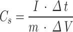
The specific capacitance was calculated from the discharge curve using the following Eq. (1):
 |
1 |
where C is the specific capacitance (F g− 1), I is the discharge current (A), Δt is the discharge time (s), m is themass of the active material (g), andΔV is the potential window (V)2.
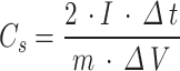
The specific capacitance of the electrode was calculated from the discharge curve using the following Eq. (2)20:
 |
2 |
where I is the discharge current, Δt is the discharge time from 0 to 1.2 V, ΔV is the voltage difference within the discharge time Δt, and m is the quality of active material on the individual electrodes.
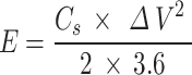
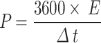
The energy density and power density of supercapacitor was calculated from the discharge curve using the following Eqs. (3–4)26:
 |
3 |
 |
4 |
where Cs represents the specifc capacitance of the electrode, ΔV is the potential window, Δt is the discharge time.
Results and discussion
The morphology of the PMCs-2 samples was examined using SEM. The field-emission scanning electron microscopy (Fig. 1a-c) image shows that the PMCs-2 possesses a monodisperse spherical shape. As shown in Fig. 1a-b, the obtained material exhibits a relatively regular spherical shape. The EDS elemental mappings of C, O, and P in the PMCs-2 sample (Fig. 1d-f) confirm that heteroatoms are homogeneously distributed within the carbon matrix.
Fig. 1.

(a-c) SEM images of PMCs-2; (b-d) EDS images of PMCs-2; (g-i) TEM images of PMCs-2.
The morphology of the PMCs samples was examined using TEM. Figure 1g-i shows the TEM images of the PMCs-2 samples. The morphology shows hierarchical porous hollow of carbon spheres, which is consistent with SEM results (Fig. 1a). Micropores (< 2 nm) and mesopores (2–50 nm) appear at higher magnification (Fig. 1g-i). As shown in Fig. 1i (inset), the selected area electron diffraction (SAED) pattern (Fig. 1i, inset) displays distinct diffraction rings, confirming the partially graphitized nature of the pore walls, which contributes to enhanced electrical conductivity.
The N2 adsorption isotherm of A-PMCs-2 and A-MCs is similar to the typical Type IV adsorption isotherm and has a good H1 hysteresis loop (Fig. 2a, c). These results indicate that the A-PMCs-2 and A-MCs samples comprise mesoporous and microporous carbon. The BET surface area of A-MCs is 139.74 m2 g− 1, with a pore volume of 0.08 cm3 g− 1, and an average pore size distribution centered at approximately 2.19 nm (Fig. 2b, d). A-PMCs-2 has a large BET surface area of 1207 m2 g− 1, a pore volume of 0.72 cm3 g− 1, and a narrow pore size distribution at about 2.4 nm (Table 1). This remarkable improvement (8.6×surface area enhancement) directly correlates with phytic acid incorporation during synthesis, which effectively promotes crosslinking reactions that develop hierarchical pore networks.
Fig. 2.

N2 adsorption isotherms and pore size distributions of A-PMCs-2 and A-MCs.
Table 1.
Specific surface areas and pore size parameters for A-MCs, and A-PMCs-2.
| Samples | BET surface area (m2 g− 1) |
Total micropore volume (cm3 g− 1) |
Average pore size (nm) |
|---|---|---|---|
| A-MCs | 139.74 | 0.08 | 2.19 |
| A-PMCs-2 | 1207.00 | 0.72 | 2.40 |
Characterization of material crystal structure using wide-angle XRD. From the wide-angle XRD spectrum (Fig. 3a-b), it can be seen that at 2θ = 23° and 2θ = 43°, all samples have significant diffraction peaks, which indicates that the material has a certain degree of graphitization structure. These peaks are assigned to diffractions from the (002), and (100) planes of graphite41, respectively. As shown in Fig. 3a, the peak morphology of materials synthesized under different temperature conditions is consistent (Consistent doping dosage), indicating that the synthesis temperature has a relatively small impact on the crystal structure. As shown in Fig. 3b, as the doping dose increases, the peak intensity increases, and the degree shifts to the right, indicating that phosphorus atom doping is beneficial for increasing the graphitization degree of material. The observed enhancement in graphitization degree can be primarily attributed to the following mechanisms involving phosphorus doping: (i) The lone pair electrons of P atoms facilitate the construction of sp²-hybridized carbon networks through orbital interaction42, (ii) The incorporated P species induce localized stress release, thereby promoting the preferential alignment of microcrystalline domains, (iii) The presence of P alters the pyrolysis kinetics of the carbon matrix, effectively reducing the energy barrier for graphitization transformation43.
Fig. 3.

a XRD patterns of A-PMCs-65 °C, A-PMCs-75 °C, A-PMCs-85 °C, and A-PMCs-95 °C; b XRD patterns of A-PMCs, A-PMCs-0.5, A-PMCs-1, A-PMCs-2, and A-PMCs-3.
The FTIR spectra of PMCs-65 °C, PMCs-75 °C, PMCs-85 °C, and PMCs-95 °C between 4000 and 400 cm− 1are given in Fig. 4a. The FTIR spectra of PMCs-0.5, PMCs-1, PMCs-2, and PMCs-3 between 4000 and 400 cm− 1are given in Fig. 4b. The absorption peak located near 3435 cm− 1 corresponds to the stretching vibration peaks of O-H and N-H. The characteristic peak at 3140 cm− 1 corresponds to the stretching vibration absorption peak of - CH2. The absorption peak at 1060 cm− 1 corresponds to the stretching vibration peak of - OH. The bending vibration peak at 1660 cm− 1 is C = C. 1400 cm− 1 is the stretching vibration absorption peak of C-P and P-O, the intensity of the peak is firm, which indicates abundant phosphorus functional groups are formed During the synthesis process. As shown in Fig. 4b, the peak intensity of PMCs-2 is more potent than other samples, suggesting that PMCs-2 contains more abundant phosphorus functional groups.
Fig. 4.

a FTIR spectra of PMCs-65 °C, PMCs-75 °C, PMCs-85 °C, and PMCs-95 °C; b FTIR spectra of PMCs-0.5, PMCs-1, PMCs-2, and PMCs-3.
As the survey spectrum shows (Fig. 5a), the XPS survey spectrum of the PMCs-2 exhibits strong signals of carbon, phosphorus, and oxygen elements. The P2p core level spectra of the PMCs-2 are shown in Fig. 5b. The PMCs-2 exhibits two peaks at the binding energy of 135.0 eV, 134.0 eV, 133.1 eV, and 132.1 eV, which can be assigned to the P-C and P-O bond. From C1s spectra (Fig. 5c), the C atoms in the prepared PMCs-2 sample exhibit mainly two bonding forms: C-C/C = C bond at 284.8 eV, C-O bond at 286.0 eV and P-C bond at 288.0 eV. From O1s spectra (Fig. 5d), the O atoms in the prepared PMCs-2 sample exhibit mainly two bonding forms: -C-O-C/OH bond at 531.3 eV, and -C = O bond at 532.7 eV.
Fig. 5.

XPS spectra of the PMCs-2: a Survey spectrum; b P2p spectra; c C1s spectra; d O1s spectra.
The electrochemical performance was characterized through cyclic voltammetry and constant current charge-discharge methods. Figure 6a displays the GCD profiles of A-PMCs synthesized at 65 °C, 75 °C, 85 °C, and 95 °C measured at a current density of 0.5 A g− 1, while Fig. 6b presents their corresponding CV curves recorded at a scan rate of 20 mV s− 1. Notably, the A-PMCs-75 °C electrode demonstrates the longest discharge time in GCD measurements (Fig. 6a), indicating its superior charge storage capability. As quantitatively compared in Fig. 7, the A-PMCs-75 °C sample achieves the highest specific capacitance of 230 F g− 1 at 0.5 A g− 1, surpassing those of 65 °C (224 F g− 1), 85 °C (203 F g− 1), and 95 °C (185 F g− 1) derived counterparts.
Fig. 6.

a Galvanostatic charge-discharge (GCD) curves for A-PMCs-65 °C, A-PMCs-75 °C, A-PMCs-85 °C, and A-PMCs-95 °C (current density of 0.5 A g− 1); b Cyclic voltammetry (CV) curves for A-PMCs-65 °C, A-PMCs-75 °C, A-PMCs-85 °C, and A-PMCs-95 °C materials between − 1 ~ 0 V (vs. Hg/HgO) in 6 M KOH aqueous solution (scan rate of 20 mV s− 1).
Fig. 7.

Specific capacitance of A-PMCs-65 °C, A-PMCs-75 °C, A-PMCs-85 °C, and A-PMCs-95 °C.
The GCD curves of A-MCs, A-PMCs-0.5, A-PMCs-1, A-PMCs-2, and A-PMCs-3 are shown in Fig. 8a (current density of 0.5 A g− 1), The CV curves of A-MCs, A-PMCs-0.5, A-PMCs-1, A-PMCs-2, and A-PMCs-3 are shown in Fig. 8b (scan rate of 20 mV s− 1). As shown in Fig. 8a, the discharge time of A-PMCs-2 is the longest, indicating its better electrochemical performance. Specific capacitances of all samples is listed in Fig. 9, the Specific capacitance of A-PMCs-2 is 257.5 F g− 1 (current density of 0.5 A g− 1). The nearly rectangular cyclic voltammetry (CV) profiles (Fig. 8b) demonstrate superior charge storage performance, with minimal peak distortion suggesting limited pseudo-capacitive contributions from surface heteroatoms in alkaline electrolyte. As shown in Fig. 8a, the galvanostatic charge-discharge (GCD) measurements of A-PMCs-2 electrodes in 6 M KOH electrolyte exhibit ideal triangular symmetry with stable voltage plateaus maintained within the − 1 to 0 V potential window. This characteristic charge-discharge behavior confirms excellent electrochemical reversibility and rapid ion transport kinetics in the synthesized material2.
Fig. 8.

a Galvanostatic charge-discharge (GCD) curves for A-MCs, A-PMCs-0.5, A-PMCs-1, A-PMCs-2, and A-PMCs-3(current density of 0.5 A g− 1); b Cyclic voltammetry (CV) curves for A-MCs, A-PMCs-0.5, A-PMCs-1, A-PMCs-2, and A-PMCs-3 materials between − 1 and 0 V (vs. Hg/HgO) in 6 M KOH aqueous solution (scan rate of 20 mV s− 1).
Fig. 9.

Specific capacitance of A-MCs, A-PMCs-0.5, A-PMCs-1, A-PMCs-2, and A-PMCs-3.
The GCD curve of A-PMCs-2 with a current density in the range of 0.5–5 A g− 1 is shown in Fig. 10a, and curves under different current densities exhibit good symmetry. Based on the calculation formula and discharge time estimation, the capacitance value can reach 257.5 F g− 1 at a current density of 0.5 A g− 1. Figure 10b displays the cyclic voltammetry (CV) curve of A-PMCs at scan rates ranging from 10 to 200 mv s− 1. When the scanning rate increases to 100 mv s− 1, the curve still shows an approximately rectangular shape, indicating its double-layer capacitive behavior. However, at a scanning rate of 200 mv s− 1, the curve shape deviates from the rectangular shape. Perhaps due to the limited movement of electrolyte ions at high scanning rates26.
Fig. 10.

a Galvanostatic charge-discharge curves for A-PMCs-2 at different current densities; b Cyclic voltammograms for A-PMCs-2 at different scan rates.
The performance of the material is the ultimate goal of the study. As shown in Fig. 11a, while using A-PMCs-2 as the electrode material to assemble a water-based button symmetric supercapacitor, the optimal voltage window for a two-electrode system is 0 ~ 1.2 V. As shown in Fig. 11b, the symmetric GCD profiles demonstrate a dominant electric double-layer charge storage mechanism, evidenced by their near-ideal charge-discharge symmetry, the specific capacitance value of the capacitor is 92.8 F g− 1. As shown in Fig. 11c, the electrochemical performance remains stable. The area of the CV curve increases continuously with the increase of scanning rate, and remains rectangular at a rate of 200 mV s− 1, with no obvious deformation.
Fig. 11.

a Potential screening of the two electrode system; b Galvanostatic charge/discharge curves at different current densities; c Cyclic voltammograms at different scan rates; d Nyquist curve; e supercapacitor cyclic stability curve. f Ragone plots of A-PMCs-2 symmetric supercapacitors and some previously reported results.
Used A-PMCs-2 as electrode material assembly into a symmetrical water system supercapacitor, it shows good conductivity, with an equivalent charge transfer resistance of Rct=0.53 Ω (Fig. 11d). In the present work, the current density of 2 A g− 1 was used to complete 5000 charge-discharge cycles to verify the cycle life of A-PMCs-2. As shown in Fig. 11e, the A-PMCs-2 exhibited good cyclic stability, losing only 1.01% of its initial capacitance after 5000 cycles. Figure 11f shows the Ragone plot of the supercapacitor assembled with A-PMCs-2 in a 6 M potassium hydroxide (KOH) electrolyte solution. The capacitor delivers an energy density of 4.64 Wh kg− 1 at a power density of 150 W kg− 1 and maintains 3.95 Wh kg− 1 at a higher power density of 1500 W kg− 1. These values surpass those of most recently reported symmetric supercapacitors based on mesoporous carbon materials, the power density and energy density of recently reported supercapacitors are shown in Table 2. Table 2 also includes key parameters such as capacitance at different current densities in the three-electrode system and cycling stability in the two-electrode system. The three-electrode system demonstrates significantly superior capacitance across various current densities compared to other materials, while the two-electrode system exhibits comparable cycling stability to other materials. The results indicate that A-PMCs-2 is a material with great potential for use as an electrode material.
Table 2.
Performance comparison data of P-doped porous carbon prepared from various materials.
| No | Electrode material | Capacitance (three-electrode) |
Cyclic stability | Energy Density | power density | References |
|---|---|---|---|---|---|---|
| 1 | Coal Tar Pitch Based Spherical Active Carbons |
153.5 F g− 1 at 0.5 A g− 1 |
0% loss at 10,000 cycles (1 A g− 1 ) | 4.16 Wh kg− 1 | 1201.9 W kg− 1 | 44 |
| 2 | Mesoporous hollow carbon spheres |
221.45 F g− 1 at 0.5 A g− 1 |
8% loss at 20,000 cycles (5 A g− 1 ) | 5.91 Wh kg− 1 | 137.5 W kg− 1 | 45 |
| 3 | Hierarchical carbon nanocages |
278 F g− 1 at 1 A g− 1 |
4.8% loss at 5000 cycles (1 A g− 1 ) | 1.8 Wh kg− 1 | 153.8 W kg− 1 | 46 |
| 4 | biomass-derived porous carbon |
103 F g− 1 at 0.1 A g− 1 |
0% loss at 20,000 cycles (2 A g− 1 ) | 3.44 Wh kg− 1 | 25 W kg− 1 | 47 |
| 5 | reclaimed carbon fiber (RCF) |
122.2 F g− 1 at 1 A g− 1 |
0% loss at 30,000 cycles (1 A g− 1 ) | 3.84 Wh kg− 1 | 93.8 W kg− 1 | 48 |
| 6 | Hierarchically porous carbon derived from tobacco waste |
196.5 F g− 1 at 0.2 A g− 1 |
6% loss at 5000 cycles (1 A g− 1 ) | 3.8 Wh kg− 1 | 482 W kg− 1 | 49 |
| 7 | P-doped porous carbon |
257.5 F g− 1 at 0.5 A g− 1 |
1.01% loss at 5000 cycles (2 A g− 1 ) | 4.64 Wh kg− 1 | 150 W kg− 1 | Current work |
Conclusions
In summary, we demonstrate a straightforward one-step synthetic method for synthesizing p-doped hierarchical carbon spheres using F127 as the soft template and phytic acid as the phosphorus source. The obtained hierarchical porous hollow of carbon spheres possess a high surface area (1207 m2 g− 1), and large amount of mesoporous (2.40 nm). Ascribed to their high specific surface area, the carbon spheres exhibit excellent performance as supercapacitor electrodes with high specific capacitance (92.8 F g− 1) at a current density of 0.5 A g− 1. The capacitance of A-PMCs-2 only loses 1.01% after 5000 charge-discharge cycles, and the energy density is 4.64 Wh kg− 1 at a power density of 150 W kg− 1. These P-doped mesoporous carbon spheres have better energy storage performance and cycling stability, indicating that the prepared mesoporous carbon materials can be applied as capacitor electrode materials.
Acknowledgements
This research was supported by the Research Program of Application Foundation of Qinghai Province (No. 2024-ZJ-787).
Author contributions
J. Zhang and Y.-L. Xie wrote the main manuscript text. All authors reviewed the manuscript.
Data availability
Data is provided within the manuscript or supplementary information files.
Declarations
Competing interests
The authors declare that they have no known competing financial interests or personal relationships that could have appeared to influence the work reported in this paper.
Footnotes
Publisher’s note
Springer Nature remains neutral with regard to jurisdictional claims in published maps and institutional affiliations.
References
- 1.Priyadharsini, I., Anbarasan, P. M., Aroulmoji, V., Siva, V. Synthesize, characterization and electrochemical investigations of Cobalt oxide nanoparticles to supercapacitor application. Aegaeum J.8(8), 751–758. https://hal.science/hal-03093575v1(2020).
- 2.Vargheese, S. et al. Triazine-based 2D covalent organic framework-derived nitrogen-doped porous carbon for supercapacitor electrode. Carbon Lett.31, 879–886. 10.1007/s42823-020-00190-6 (2021). [Google Scholar]
- 3.Xu, X. N. et al. Li3VO4 nanoparticles in N-doped carbon with porous structure as an advanced anode material for lithium-ion batteries. Chem. Eng. J.370, 606–613. 10.1016/j.cej.2019.03.167 (2019). [Google Scholar]
- 4.Jeevan, T. S. M. A., Tadele, G., Yizengaw, L. & Johnson, M. F. G. Review on recent progress of nanostructured anode materials for Li-ion batteries. Am. J. Anal. Chem.13, 431–448. 10.4236/ajac.2022.1311029 (2022). [Google Scholar]
- 5.Hou, Z. X., Shi, P. & Zou, S. N. Three-dimensional porous graphene/polyaniline hybrids for high performance supercapacitor electrodes. Res. Application Mater. Sci.210.33142/msra.v2i1.1974 (2020).
- 6.Meng, Y. N., Wang, K., Zhang, Y. J. & Wei, Z. X. Hierarchical porous graphene/polyaniline composite film with superior rate performance for flexible supercapacitors. Adv. Mater.25, 6985–6990. 10.1002/adma.201303529 (2013). [DOI] [PubMed] [Google Scholar]
- 7.Dai, Y. Y., Liu, C. L., Bai, Y., Kong, Q. & Pang, H. Framework materials for supercapacitors. Nanatechnol. Reviews. 11, 1005–1046. 10.1515/ntrev-2022-0042 (2022). [Google Scholar]
- 8.Katkar, P. K. et al. Self-assembly of Sr2P2O7@2D rGO nano/micro-architecture for highly durable and bendable solid-state supercapattery[J]. Mater. Today Phys.46, 101510. 10.1016/j.mtphys.2024.101510 (2024). [Google Scholar]
- 9.Katkar, P. K. et al. Rational design of redox active amorphous Ni-Mn phosphate anchored on vertical graphene Nanohills (VGNHs) for solid-state energy storage device[J]. J. Alloys Compd.968, 171935. 10.1016/j.jallcom.2023.171935 (2023). [Google Scholar]
- 10.Katkar, P. K. et al. In-situ growth of 3D amorphous Ni-Co-Mn phosphate on 2D Ti3C2Tx nanocomposite for commercial-level hybrid energy storage application[J]. J. Mater. Sci. Technol.206, 282–296. 10.1016/j.jmst.2024.03.044 (2025). [Google Scholar]
- 11.Aman, S. et al. Hydrothermal development of bimetallic sulfide nanostructures as an electrode material for supercapacitor application. Energy Fuels. 37, 17473–17483. 10.1021/acs.energyfuels.3c03380 (2023). [Google Scholar]
- 12.Liu, B. L. et al. Fabrication of nickel Cobalt bimetallic sulfide doped graphite carbon nanohybrids as electrode materials for supercapacitors. Diam. Relat. Mater.124, 108955. 10.1016/j.diamond.2022.108955 (2022). [Google Scholar]
- 13.Jeon, G., Hg Baek, S., Lee, S. & Kim, S. W. Metal oxide/graphene composites for supercapacitive electrode materials. Chemistry–An Asian J.11, 949–964. 10.1002/asia.201501072 (2016). [DOI] [PubMed] [Google Scholar]
- 14.Cao, Y. Y. et al. Stability study of transition metal oxide electrode materials. J. Power Sources. 560, 232710. 10.1016/j.jpowsour.2023.232710 (2023). [Google Scholar]
- 15.Biswas, S. et al. Hollow nanostructures of metal oxides as emerging electrode materials for high performance supercapacitors. CrystEngComm22, 1633–1644. 10.1039/c9ce01547g (2020). [Google Scholar]
- 16.Ok, B., Gencten, M., Arvas, M. B. & Sahin, Y. One-pot synthesis of Vanadium-doped conducting polymers for using as electrode materials of supercapacitors. J. Mater. Sci.: Mater. Electron.34, 1690. 10.1007/s10854-023-11102-5 (2023). [Google Scholar]
- 17.Sardana, S., Gupta, A., Singh, K., Maan, A. S. & Ohlan, A. Conducting polymer hydrogel based electrode materials for supercapacitor applications. J. Energy Storage. 45, 103510. 10.1016/j.est.2021.103510 (2022). [Google Scholar]
- 18.Zhu, Y. H. et al. MnO2-MXene composite as electrode for supercapacitor. J. Electrochem. Soc.169, 030524. 10.1149/1945-7111/ac59f5 (2022). [Google Scholar]
- 19.Rajeeve, A. D., Yamuna, R., Vinoba, M. & Bhagiyalakshmi, M. β-Cyclodextrin-Stabilized CuO/MXene nanocomposite as an electrode material for High-Performance supercapacitors. Langmuir39, 17688–17699. 10.1021/acs.langmuir.3c02140 (2023). [DOI] [PubMed] [Google Scholar]
- 20.Shi, L. W. et al. Metal-organic frameworks-derived porous carbon nanotube for high performance supercapacitor electrode materials. Colloids Surf. Physicochemical Eng. Aspects. 652, 129862. 10.1016/j.colsurfa.2022.129862 (2022). [Google Scholar]
- 21.Kang, X. Y. et al. 3D juniperus sabina-like Ni/Co metal-organic framework as an enhanced electrode material for supercapacitors. J. Solid State Chem.310, 123056. 10.1016/j.jssc.2022.123056 (2022). [Google Scholar]
- 22.Yang, Y. X., Ge, K. K., Rehman, S. U. & Bi, H. Nanocarbon-based electrode materials applied for supercapacitors. Rare Met.41, 3957–3975. 10.1007/s12598-022-02091-1 (2022). [Google Scholar]
- 23.Hong, S. et al. Hierarchical porous carbon materials prepared by direct carbonization of Metal–Organic frameworks as an electrode material for supercapacitors. Bull. Korean Chem. Soc.42, 309–314. 10.1002/bkcs.12145 (2021). [Google Scholar]
- 24.Ilnicka, A., Skorupska, M., Szkoda, M., Zarach, Z. & Lukaszewicz, J. P. N-doped carbon materials as electrodes for highly stable supercapacitors. Mater. Res. Lett.11, 213–221. 10.1080/21663831.2022.2139163 (2023). [Google Scholar]
- 25.Zhang, M., Liu, H., Shi, T. & Zha, R. H. Nanocasting and direct synthesis strategies for mesoporous carbons as supercapacitor electrodes. Chem. Mater.30, 7391–7412. 10.1021/acs.chemmater.8b03345 (2018). [Google Scholar]
- 26.Wang, Z. Q. et al. Synthesis of N-doped hierarchical carbon spheres for CO2 capture and supercapacitors. RSC Adv.6, 1422–1427. 10.1039/c5ra20484d (2016). [Google Scholar]
- 27.Sutanu, K., Majee, R. & Bhattacharyya, S. Chemical modifications of porous carbon nanospheres obtained from ubiquitous precursors for targeted drug delivery and live cell imaging. ACS Sustain. Chem. Eng.6, 8503–8514. 10.1021/acssuschemeng.8b00785 (2018). [Google Scholar]
- 28.Djandja, O. S. et al. Synthesis of N-doped carbon material via hydrothermal carbonization: effects of reaction solvent and nitrogen source. J. Energy Storage. 60, 106588. 10.1016/j.est.2022.106588 (2023). [Google Scholar]
- 29.Rawal, S. G., Kuma Yr, Mandal, U. K., Kumar, A., Tanwar, R. & Joshi, B. Synthesis and electrochemical study of phosphorus-doped porous carbon for supercapacitor applications. SN Appl. Sci.3, 1–14. 10.1007/s42452-021-04187-2 (2021). [Google Scholar]
- 30.Wang, Y. X. et al. Achieving high-performance room-temperature sodium–sulfur batteries with S@ interconnected mesoporous carbon Hollow nanospheres. J. Am. Chem. Soc.138, 16576–16579. 10.1021/jacs.6b08685 (2016). [DOI] [PubMed] [Google Scholar]
- 31.Liang, J. et al. Sulfur and nitrogen dual-doped mesoporous graphene electrocatalyst for oxygen reduction with synergistically enhanced performance[J]. Angew. Chem.124 (46), 11664–11668. 10.1002/anie.201206720 (2012). [DOI] [PubMed] [Google Scholar]
- 32.Chen, Z. et al. Highly active nitrogen-doped carbon nanotubes for oxygen reduction reaction in fuel cell applications[J]. J. Phys. Chem. C. 113 (49), 21008–21013. 10.1021/jp908067v (2009). [Google Scholar]
- 33.Yang, D. S., Bhattacharjya, D., Song, M. Y. & Yu, J. S. Highly efficient metal-free phosphorus-doped platelet ordered mesoporous carbon for electrocatalytic oxygen reduction. Carbon67, 736–743. 10.1016/j.carbon.2013.10.065 (2014). [Google Scholar]
- 34.Zhu, Y. P. et al. Direct synthesis of Phosphorus-Doped mesoporous carbon materials for efficient electrocatalytic oxygen reduction. Chem. Cat Chem.7, 2903–2909. 10.1002/cctc.201500148 (2015). [Google Scholar]
- 35.Rong, H. Q. et al. ZIF-8 derived nitrogen, phosphorus and sulfur tri-doped mesoporous carbon for boosting electrocatalysis to oxygen reduction in universal pH range. Electrochim. Acta. 318, 783–793. 10.1016/j.electacta.2019.06.122 (2019). [Google Scholar]
- 36.Zhang, Z. P., Sun, J. T., Dou, M. L., Ji, J. & Wang, F. Nitrogen and phosphorus codoped mesoporous carbon derived from polypyrrole as superior metal-free electrocatalyst toward the oxygen reduction reaction. ACS Appl. Mater. Interfaces. 9, 16236–16242. 10.1021/acsami.7b03375 (2017). [DOI] [PubMed] [Google Scholar]
- 37.Paixão, G. R. et al. Synthesis of mesoporous P–doped carbon and its application in propranolol drug removal: characterization, kinetics and isothermal studies. Chem. Eng. Res. Des.187, 225–239. 10.1016/j.cherd.2022.09.009 (2022). [Google Scholar]
- 38.Huang, K. C. et al. Adsorption of antibiotics from wastewater by cabbage-based N, P co-doped mesoporous carbon materials. J. Clean. Prod.391, 136174. 10.1016/j.jclepro.2023.136174 (2023). [Google Scholar]
- 39.Gong, H. X. et al. Phosphorus-doped mesoporous carbon derived from waste tires as anode for K-ion batteries. Mater. Lett.285, 128983. 10.1016/j.matlet.2020.128983 (2021). [Google Scholar]
- 40.Qu, Y. N. Synthesis of nitrogen and phosphorus co-doped carbon with tunable hierarchical porous structure from rice husk for high performance supercapacitors. Int. J. Electrochem. Sci.15, 2399–2413. 10.20964/2020.03.43 (2020). [Google Scholar]
- 41.Xia, Y. & Mokaya, R. Synthesis of ordered mesoporous carbon and nitrogen-doped carbon materials with graphitic pore walls via a simple chemical vapor deposition method. Adv. Mater.16, 1553–1558. 10.1002/adma.200400391 (2004). [Google Scholar]
- 42.Chang, G. et al. How heteroatoms (Ge, N, P) improve the electrocatalytic performance of graphene: theory and experiment[J]. Sci. Bull.10.1016/j.scib.2018.01.013 (2018). [DOI] [PubMed] [Google Scholar]
- 43.Li, W. et al. Heteroatom-doped and graphitization-enhanced lignin-derived hierarchically porous carbon via facile assembly of lignin-Fe coordination for high-voltage symmetric supercapacitors[J]. J. Colloid Interface Sci.659, 374–384. 10.1016/j.jcis.2023.12.162 (2024). [DOI] [PubMed] [Google Scholar]
- 44.Mo, B. et al. Supercapacitor performances of coal Tar pitch based spherical active carbons fabricated by the SiO2 template method[J]. J. Chem. Eng. Jpn.56 (1), 2217863. 10.1080/00219592.2023.2217863 (2023). [Google Scholar]
- 45.Jiang, J. et al. Controllable construction of mesoporous Hollow carbon spheres rich in micropores from waterborne benzoxazine and their application in supercapacitors. Surf. Interfaces. 52, 104844. 10.1016/j.surfin.2024.104844 (2024). [Google Scholar]
- 46.Zhao, J. et al. Enlarging ion-transfer micropore channels of hierarchical carbon nanocages for ultrahigh energy and power densities. Sci. China Mater. 64 9. 2173–2181. 10.1007/s40843-020-1614-5 (2021).
- 47.Zhang, Y. et al. Synthesis and electrochemical performance of biomass-derived porous carbon materials for supercapacitors[J]. J. Mater. Sci.: Mater. Electron.35 (2), 116. 10.1007/s10854-024-11944-7 (2024). [Google Scholar]
- 48.Zhao, C. et al. Surface engineering of reclaimed carbon fiber (RCF) electrode for superimposed supercapacitor performance[J]. J. Energy Storage. 46, 103786. 10.1016/j.est.2021.103786 (2022). [Google Scholar]
- 49.Liu, Y., Cheng, X. & Zhang, S. Hierarchically porous carbon derived from tobacco waste by one-step molten salt carbonization for supercapacitor[J]. Carbon Lett.32 (1), 251–263. 10.1007/s42823-021-00271-0 (2022). [Google Scholar]
Associated Data
This section collects any data citations, data availability statements, or supplementary materials included in this article.
Data Availability Statement
Data is provided within the manuscript or supplementary information files.