

Abstract
Background
Modular dual mobility (DM) bearings have a junction between a cobalt chrome alloy (CoCrMo) liner and titanium shell, and the risk of tribocorrosion at this interface remains a concern. The purpose of this study was to determine whether liner malseating and liner designs are associated with taper tribocorrosion.
Methods
We evaluated 28 retrieved modular DM implants with a mean in situ duration of 14.6 months (range, 1 to 83). There were two manufacturers included (12 and 16 liners, respectively). Liners were considered malseated if a distinct divergence between the liner and shell was present on postoperative radiographs. Tribocorrosion was analyzed qualitatively with the modified Goldberg Score (mGS) and quantitatively with an optical coordinate-measuring machine. An acetabular shell per manufacturer was sectioned for metallographic analysis.
Results
There were six implants (22%) that had severe grade 4 corrosion, six (22%) had moderate grade 3, 11 (41%) had mild grade 2, and five (18.5%) had grade 1 or no visible corrosion. The average volumetric material loss at the taper was 0.086 ± 0.19 mm3. There were seven liners (25%) that had radiographic evidence of malseating, and all were of a single design (P = 0.01). The two liner designs were fundamentally different from one another with respect to the CoCrMo alloy type, taper surface finish, and shape deviations. Malseating was an independent risk factor for increased volumetric material loss (P = 0.017).
Conclusion
Dual mobility tribocorrosion with quantifiable material loss occurred more commonly in malseated liners. Specific design characteristics may make liners more prone to malseating, and the interplay between seating mechanics, liner characteristics, and patient factors likely contributes to the shell/liner tribocorrosion environment.
Level of Evidence:
Level III
Keywords: dual mobility, corrosion, total hip arthroplasty
INTRODUCTION
Instability remains the most common reason for revision total hip arthroplasty (THA) [1]. As the number of revision THA procedures is expected to double over the next decade, the use of dual mobility (DM) bearings has increased rapidly as a potential means of preventing or treating instability [1–4]. As of 2018, DM bearings were used in 12% of primary THA and 31% of revision THA [2]. The DM implants are available in both monobloc and modular designs. Modular designs allow for additional screw fixation and attempt to optimize the properties of metallic components, with a titanium alloy shell for ingrowth and a polished cobalt-chromium alloy (CoCrMo) liner as a bearing surface [3]. However, this metal-on-metal junction between the liner and shell is associated with unique risks, such as malseating, dissociation, and tribocorrosion [3, 4].
The incidence of DM liner malseating has been reported to be between 1 and 16% [5, 6]. Malseating of the DM liner can occur due to bony or soft-tissue interposition, prominent screws, or component deformation during impaction [6]. Compared to standard polyethylene liners, the stiffness of the CoCrMo DM liner appears to increase the risk of malseating [7, 8]. The clinical implications of liner malseating are unclear. An in vitro study demonstrated that highly malseated liners are at increased risk of corrosion at physiologic loads [6]; however, this has yet to be proven in vivo.
Recent studies have identified tribocorrosion at the taper junction between the CoCrMo liner and the titanium alloy shell with variable incidence, with some studies reporting as high as 97% [9, 10]. Junctions between dissimilar metals may be at increased risk for tribocorrosion, and the risk increases further with longer durations in situ [11, 12]. While the clinical relevance of DM liner tribocorrosion is unknown, it remains a source of concern. Studies have identified elevated serum metal levels in up to 24% of patients who have modular DM implants [4, 13], but it is unclear whether shell/liner tribocorrosion can contribute to the development of a lymphocyte-dominated adverse local tissue reaction (ALTR), similar to that seen in THA with metal-on-metal bearings or tribocorrosion at the head/neck or neck/stem taper junction. The largest retrieval study to date examined 60 modular DM liners, and although 13% had histologic evidence of tribocorrosion-related inflammation, there were no cases of ALTR [9].
To our knowledge, no published study has evaluated whether an association may exist between modular DM malseating, shell/liner tribocorrosion, and liner geometry. Additionally, most prior studies have included only a single component design, whereas experience with other modular acetabular components has proven that implant design may contribute to tribocorrosion and malseating [8, 14, 15]. Therefore, the purposes of this study were to: 1) assess the extent of tribocorrosion on the CoCr liner backside taper both qualitatively and quantitatively; 2) determine the prevalence of malseating within the study cohort, and its potential association with tribocorrosion; and 3) identify differences between different DM CoCrMo liner designs and the implications on malseating and tribocorrosion.
MATERIALS AND METHODS
There were 28 modular DM liners with a mean in situ duration of 14.6 months (range, 0.9 to 83.1) that were retrieved as part of our Institutional Review Board (IRB) approved implant retrieval program. There were two different implant designs retrieved and evaluated, including the Stryker MDM (Stryker, Kalamazoo, Michigan) in 16 cases (57.1%) and the Zimmer-Biomet G7 (Zimmer-Biomet, Warsaw, Indiana) in 12 cases (32.1%) (Figure 1). Patient data and operative reports were reviewed to determine indication for DM and intraoperative findings at DM explantation (Table 1).
Figure 1.
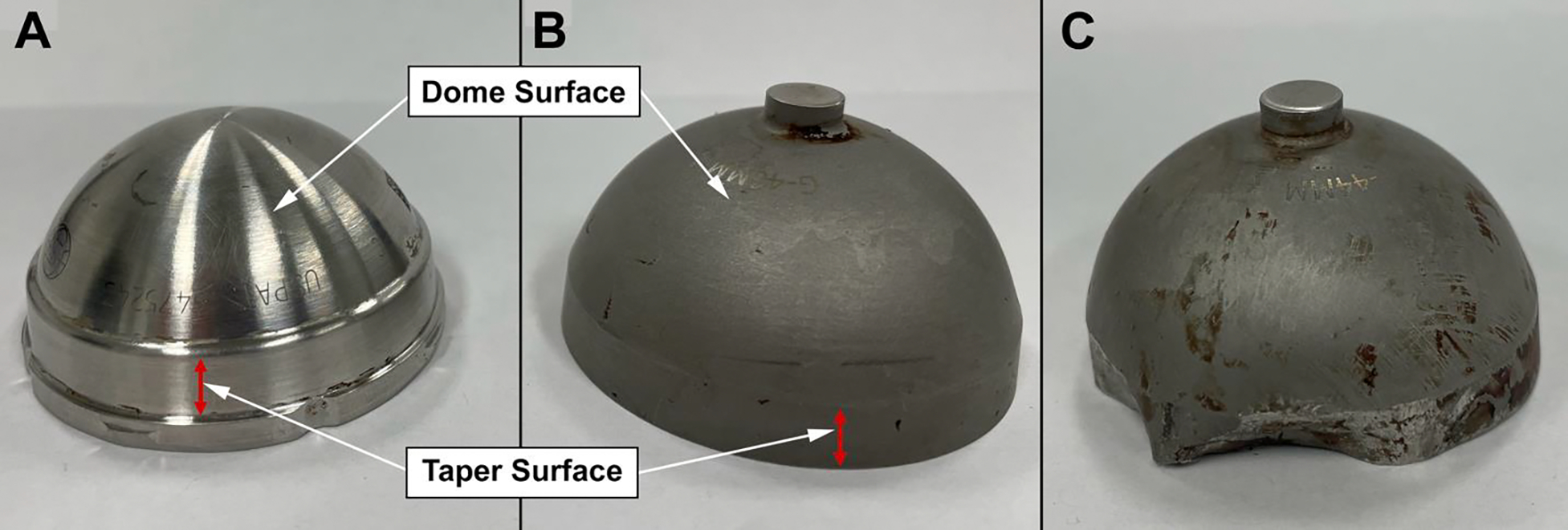
Examples of a A) MDM and B) G7 modular liner. Multiple liner design differences are visible, most notably the MDM has a machined surface finish while the G7 appears to have sandblasted finish. C) Evidence of G7 liner deformation which occurred at the time of explantation.
Table 1.
Patient and liner characteristics
| Patient | Age (years) | Sex | DM implantation Procedure Type | Reason for Revision and DM explant | Duration In-Situ (months) | Liner Type | Malseated | mGS | Volumetric Material Loss (mm3) | Maximum Linear Penetration (μm) |
|---|---|---|---|---|---|---|---|---|---|---|
|
| ||||||||||
| 1 | 75 | M | Revision | Infection | 35.4 | MDM | Yes | 2 | 0 | 0 |
| 2 | 59 | M | Revision | Instability | 4.2 | MDM | Yes | 2 | 0 | 0 |
| 3 | 62 | F | Primary | Loosening | 49.2 | MDM | Yes | 4 | 0.597 | 8.80 |
| 4 | 55 | F | Primary | Loosening | 12.2 | MDM | Yes | 4 | 0.522 | 10.71 |
| 5 | 77 | M | Conversion | Loosening | 83.1 | MDM | Yes | 4 | 0.371 | 18.55 |
| 6 | 49 | M | Revision | Infection | 1.0 | MDM | No | 1 | 0 | 0 |
| 7 | 66 | F | Revision | Infection | 1.2 | MDM | No | 1 | 0 | 0 |
| 8 | 76 | F | Revision | Instability | 6.2 | MDM | No | 2 | 0 | 0 |
| 9 | 65 | F | Conversion | Instability | 1.9 | MDM | No | 2 | 0 | 0 |
| 10 | 51 | F | Conversion | Fracture | 1.2 | MDM | No | 2 | 0 | 0 |
| 11 | 48 | F | Revision | Loosening | 7.5 | MDM | No | 3 | 0.058 | 2.10 |
| 12 | 90 | M | Conversion | Infection | 1.3 | G7 | No | 1 | 0 | 0 |
| 13 | 62 | F | Primary | Impingement | 2.4 | G7 | No | 2 | 0 | 0 |
| 14 | 77 | F | Primary | Infection | 3.5 | G7 | No | 2 | 0 | 0 |
| 15 | 70 | M | Revision | Instability | 8.2 | G7 | No | 2 | 0 | 0 |
| 16 | 76 | F | Conversion | Loosening | 11.0 | G7 | No | 3 | 0 | 0 |
| 17 | 90 | M | Revision | Infection | 10.1 | G7 | No | 4 | - | - |
| 18 | 72 | F | Primary | Loosening | 11.9 | MDM | No | 1 | 0 | 0 |
| 19 | 65 | F | Primary | Loosening | 49.2 | MDM | Yes | 3 | 0 | 0 |
| 20 | 57 | F | Revision | Loosening | 5.6 | MDM | No | 1 | 0 | 0 |
| 21 | 63 | M | Revision | Infection | 5.4 | G7 | No | 3 | - | - |
| 22 | 57 | F | Revision | Loosening | 10.5 | G7 | No | 3 | - | - |
| 23 | 80 | F | Revision | Instability | 1.4 | G7 | No | 2 | 0 | 0 |
| 24 | 64 | F | Revision | Instability | 4.6 | G7 | No | 2 | 0 | 0 |
| 25 | 57 | M | Primary | Loosening | 19.6 | MDM | Yes | 4 | 0.515 | 45.8 |
| 26 | 68 | F | Primary | Infection | 35.2 | MDM | No | 4 | 0 | 0 |
| 27 | 64 | F | Primary | Infection | 2.6 | G7 | No | 2 | 0.079 | 6.80 |
| 28 | 62 | F | Primary | Impingement | 24.3 | G7 | No | - | 0 | 0 |
There were 15 implants (53.6%) retrieved from primary THAs, and 13 implants (46.4%) from revision THAs. The majority of patients were women (n = 19, 67.9%). Patients had a mean BMI of 31.0 (range 17.8 to 42.8). The indications for implant removal were aseptic loosening in ten cases (seven cases of acetabular component aseptic loosening, two cases of femoral component aseptic loosening, and one case of aseptic loosening of both components), infection in nine cases, instability in six cases, iliopsoas tendonitis/anterior impingement in two cases, and acute acetabular fracture secondary to a fall in one case.
At the time of retrieval, one patient (patient 8) was found to have metallic debris within the capsule with evidence of impingement of the femoral neck against the rim of the acetabular component. A patient (patient 16) was found to have evidence of ALTR, but had previously been revised for ALTR prior to implantation of the DM component studied here. Femoral head material was ceramic in 12 cases (42.9%), CoCrMo in 10 cases (35.7%), unknown in five cases (17.9%), and Oxinium in one case (3.6%).
Laboratory Evaluation
The metal liners were decontaminated in 10% neutral buffered formalin for a minimum of 72 hours, and then rinsed in running tap water for 15 minutes. The backside of each liner was examined under a stereo microscope (SMZ-U, Nikon, Melville, New York) at 10 to 50X. Both the taper and the spherical dome portion of the liner backside were viewed and damage features were evaluated. Damage on the taper liner—that is by design in direct mechanical contact with the corresponding taper on the shell—was scored by two independent graders (RP and DJH) for the degree of surface damage due to fretting and corrosion based on the Goldberg scoring as modified by Kolz et al.[10, 16] For this scoring system, a score of 1 was given to tapers with no visible tribocorrosion; a score of 2 (mild) for taper surfaces with < 30% of the surface exhibiting discoloration, with minimal fretting; a score of 3 (moderate) for tapers with > 30% surface discoloration, but < 10% containing black debris, pits, or etched marks, with moderate fretting; and a score of 4 (severe) for tapers with > 10% of the surface containing black debris, pits, or etched marks, with more severe fretting or flattening of the taper. If there was any disagreement in scoring, the implants were re-reviewed and a consensus made before giving the implant a final grade. The dome portion of the liner backside is not intended to be in contact with the cup and was therefore not scored using the mGS. Instead, any type of damage features or deposits on the done were noted for further evaluation.
Taper surfaces with moderate to severe damage and dome areas with visible damage features were viewed under a scanning electron microscope (SEM) (JSM-IT 500 HR/LV, JEOL, Peabody, Massachusetts) at magnifications between 100X and 5000X to determine local damage modes based on the present damage features. The chemical compositions of deposits and films were determined by energy dispersive X-ray spectroscopy (EDS) (Aztec, Oxford Instruments, Concord, Massachusetts).
Quantification of material loss was conducted with an optical coordinate measuring machine (OrthoLux, RedLux, Romsey, United Kingdom) equipped with a white light confocal sensor. The tapered surface on the liner backside was scanned with 2 data points per degree and 70 rotations per millimeter. The original taper surfaces were digitally reconstructed based on optically identified damage free areas. The dome area of the liner’s backside was scanned with 1,080 data points per rotation and 3 rotations per degree in cases with visible damage. In the case of G7 liners, the apical centering knob had to be removed prior to scanning. Areas free of damage were used to reconstruct the original surface with an ellipsoidal fit. After data processing, maximum linear penetration and volumetric material loss from the taper and dome surface were determined. Furthermore, heat maps were generated to illustrate the location of fretting and corrosion damage, as well as light intensity maps that provided a photorealistic representation of the tapered surfaces. There were three liners of the G7 type (patients 17, 21, 22) that were grossly deformed during retrieval, which precluded coordinate measuring machine (CMM) analysis.
Radiographic Evaluation
The earliest available postoperative radiographs after DM insertion, including both anterior-posterior (AP) and cross-table lateral views, for each patient were evaluated independently by two authors for evidence of malseating. The methodology for radiographic evaluation of malseating has been previously described [6]. Malseating was defined as a distinct divergence or gapping between the liner and shell that was observed on any view (Figure 2). Findings were categorized as definitely malseated, not malseated, or indeterminate. Any disagreement between the initial reviewers or radiographs classified as “indeterminate” were subsequently reviewed by a senior author (DN).
Figure 2:
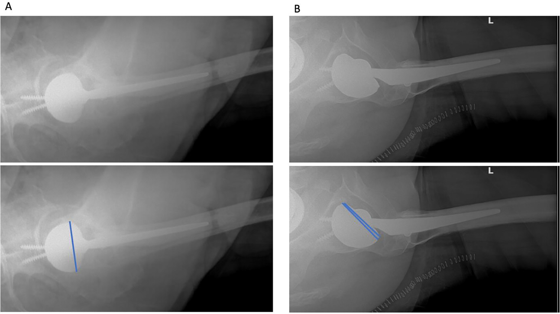
Cross-table lateral radiographs demonstrating examples of a A) well-seated, and B) malseated dual mobility liner.
Liner Design and Microstructure
A single cup per manufacturer was then sectioned for metallographic analysis (polishing, etching, and microscopic evaluation of grain structure) and determination of the bearings’ wall thickness.
Data Analyses
All statistical analyses were performed with Stata SE Version 15.1 (StataCorp, College Station, Texas), with a significance level set at P < 0.05. Univariate comparisons of continuous and categorical variables were performed with Student’s T- and Fischer’s exact tests, respectively. Correlations between continuous variables were assessed with Spearman’s rank correlation coefficients. To control for potential confounders on tribocorrosion parameters, the effect of malseating, implant design, and time in situ were evaluated using multivariate linear regressions.
SOURCE OF FUNDING
The laboratory analysis was supported by the National Institutes of Health NIH/NIAMS grant R56 AR070181.
RESULTS
Fretting and Corrosion Analysis of the Taper Surface
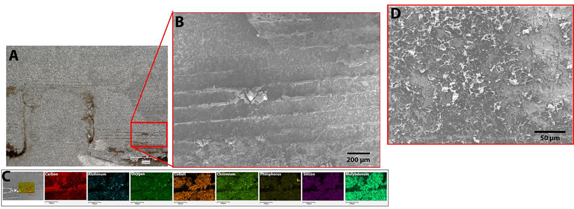
Based on the mGS at the taper surface, six implants (22%) had severe grade 4 corrosion, six (22%) had moderate grade 3, 11 (41%) had mild grade 2, and five (18.5%) had grade 1 or no visible corrosion. The damage features on MDM liner tapers were consistent with fretting and fretting corrosion based on microscopic evidence (Figure 3). There was one case that additionally exhibited a stripe of etching, which is a chemically dominated corrosion process (Patient 5; Figure 4) [17]. Actual fretting or corrosion damage features could not be observed on the taper surface of G7 liners, despite the fact that nearly all of these components appeared to have visible damage when evaluated by light microscopy and scored by mGS (Table 1). Evaluation of G7 liner tapers with light microscopy indicated the occurrence of imprinting, where parallel lines with the same spacing as machining lines of the titanium alloy acetabular shell could be observed on the backsides of the CoCrMo liner (Figure 5). However, scanning electron microscopy and chemical analysis by means of EDS revealed that these lines were organic deposits that accumulated between machining lines and adhered to the CoCrMo surface (Figure 5C). The SEM imaging of the deposits indicated a morphology indicative of fibrous tissue rather than corrosion debris (Figure 5D).
Figure 3:
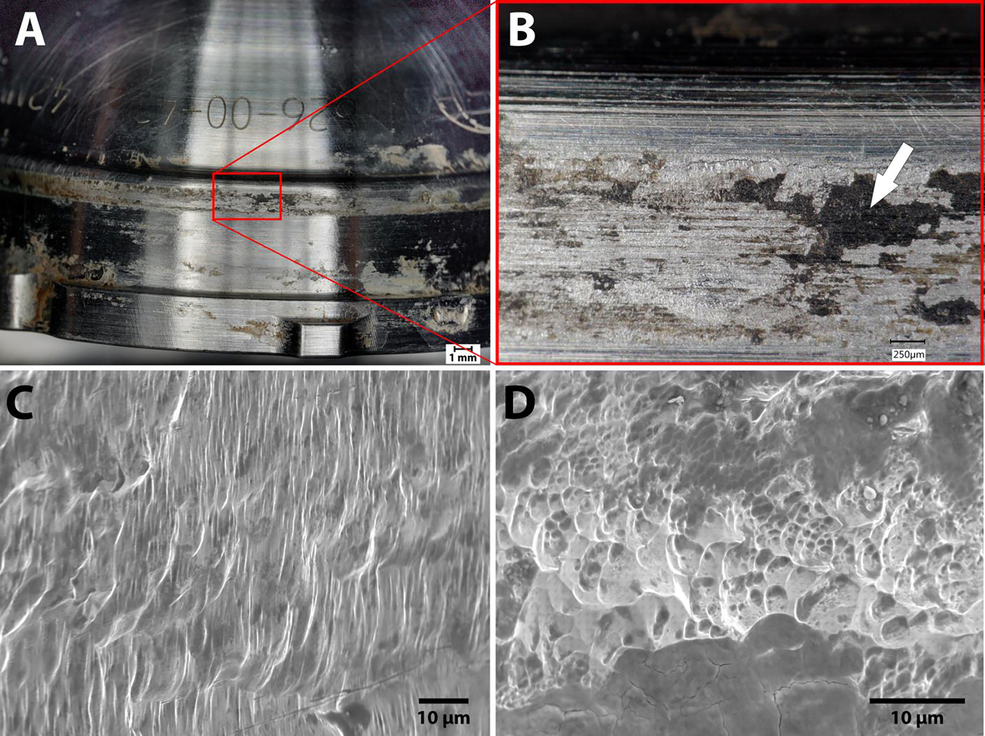
A) MDM liner with severe damage. B) Light microscopy image of damaged area (inset A). The deposits on the liner (arrow) were identified by energy dispersive X-ray spectroscopy (EDS) as chromium oxides. C, D) and scanning electron microscope (SEM) micrographs of the area in B showing fretting corrosion damage (X1300, X2500).
Figure 4:
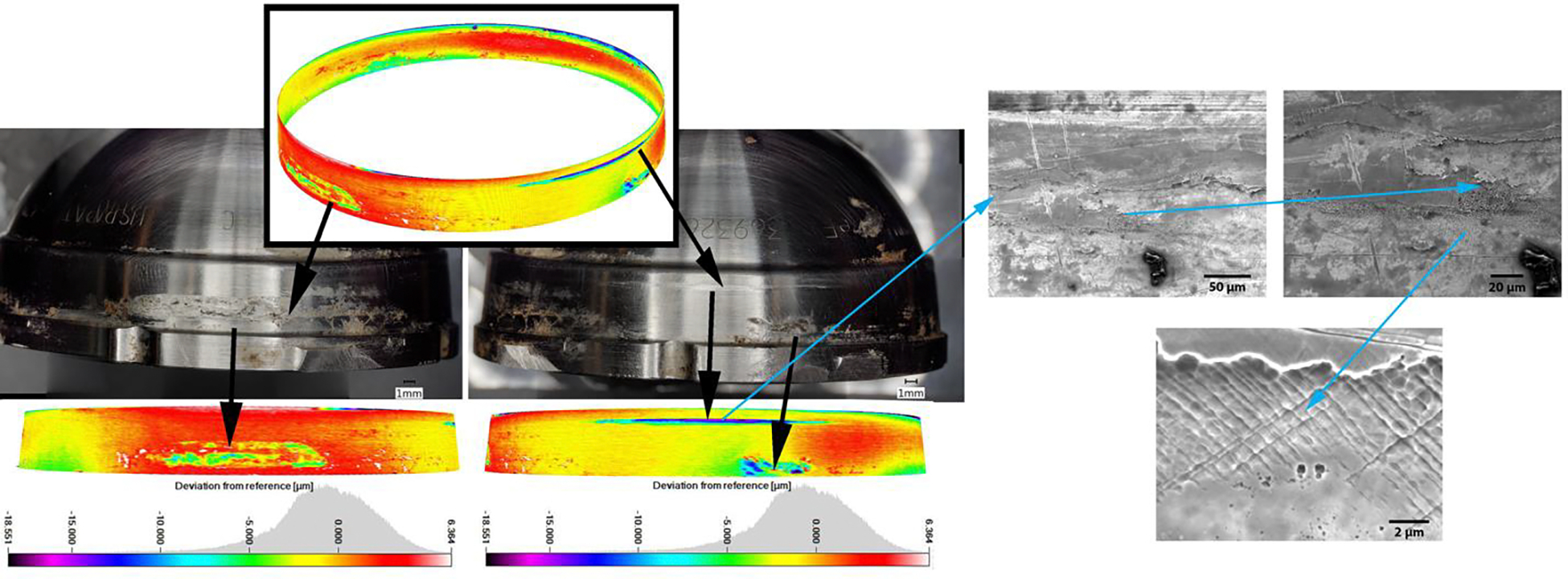
Heat maps of an MDM liner taper surface illustrating isolated local damage scars (patient 5). Total volume loss for the liner was calculated by adding volume losses from the localized areas. Material loss for this liner was 0.37 mm3. The scanning electron microscope (SEM) images (right) within the indicated damage scar demonstrates the presence of local pitting corrosion and etching (chemically induced damage modes).
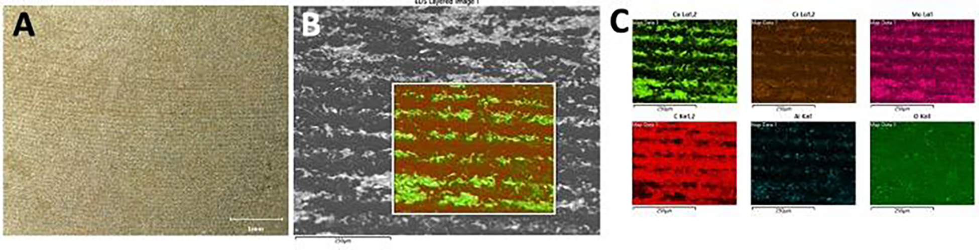
Figure 5:
A) Light microscopy image of G7 liner with damage features suggesting imprinting. B) Scanning electron microscope (SEM) images revealed the parallel lines on the surface to be organic residue with an appearance similar to fibrous tissue. C) This was further confirmed by energy dispersive X-ray spectroscopy (EDS) to be primarily composed of carbon. D) Scanning electron microscope (SEM) imaging of the deposits indicated a morphology indicative of fibrous tissue rather than corrosion debris.
Volumetric material loss and maximum linear penetration depth were calculated for 25 out of 28 liners. There were three liners that could not be assessed with CMM analysis due to major deformation during explantation. However, a visual inspection of these deformed liners revealed no evidence of corrosion damage. Among all tapers measured, the average volumetric material loss was 0.086 ± 0.19 mm3, with an average maximum linear penetration of 3.71 ± 9.87 μm. There were four liners (16%) that had a maximum linear penetration > 7 μm, which has been previously established as a potentially clinically relevant threshold [10, 18]. Among the 12 liners with an mGS of 3 or 4 (5 G7, 7 MDM), the average taper volumetric material loss was 0.24 ± 0.26 mm3, with an average taper maximum linear penetration of 10.31 ± 14.70 μm. On univariate analysis, mGS was positively correlated with time in situ (r = 0.703, P < 0.001), volumetric material loss (r = 0.765, P < 0.001), and maximum linear penetration (r = 0.765, P < 0.001).
Fretting and Corrosion Analysis of the Dome Surface
Based on light microscopy evaluation, neither the MDM nor the G7 liner had obvious corrosion damage at the dome area. Both liners had numerous organic deposits on the surface that were brown or orange in color. Due to the rougher initial surface topography of the G7 liner, there was more organic residue still present after cleaning. There were two MDM liners and three G7 liners that exhibited damage associated with contact between the screw hole and/or screw head used to secure the corresponding shell (Figure 6). Both liners also exhibited isolated areas of damage, which appeared to be plastic deformation likely caused during removal or subsequent handling (Figure 6). There were six liners of both types that also exhibited circumferential lines reminiscent of imprinting on the backside dome of the liner. Similar to the G7 taper surface, this feature was the result of organic deposits that accumulated within the machine line topography of the corresponding shell and transferred to the liner backside. The SEM/EDS confirmed the presence of lines of carbon-rich materials as well as the presence of aluminum-oxide particles within the rough surface topography (Figure 7). The latter suggests that aluminum-oxide blasting was used as the final step of the surface finishing process, resulting in the characteristic surface topography of the G7 liner surface.
Figure 6:

A) Photograph and scanning electron microscope (SEM) image of a screw hole scar within the dome area of a MDM liner backside dome. B) Damage scar likely caused during liner removal.
Figure 7:
A) Photograph of an imprinting-like pattern on the backside dome area of a G7 liners. B) Higher magnification scanning electron microscope (SEM) image of the same general area. C) Energy dispersive X-ray spectroscopy (EDS) mapping reveals carbon rich nature of the imprinting-like pattern indicating adherence of organic matter, and presence of fine aluminum oxide particles that likely originate from the surface finishing process.
Wear maps and intensity images from CMM data were generated for cases with screw- or screw-hole-related wear scars. Only some of these apparent wear scars were associated with quantifiable material loss (Figure 8). The total material loss in these cases was 0.051 mm3 (patient 20) and 0.009 mm3 (patient 19) for MDM liners, and 0.005 mm3 (patient 14) and 0.084 mm3 (patient 16) for the G7 liners. There was one G7 liner (patient 22) that had no quantifiable material loss despite visible screw hole marks. The SEM/EDS analysis further revealed titanium alloy material transfer associated with these screw hole scars (Figure 8).
Figure 8.
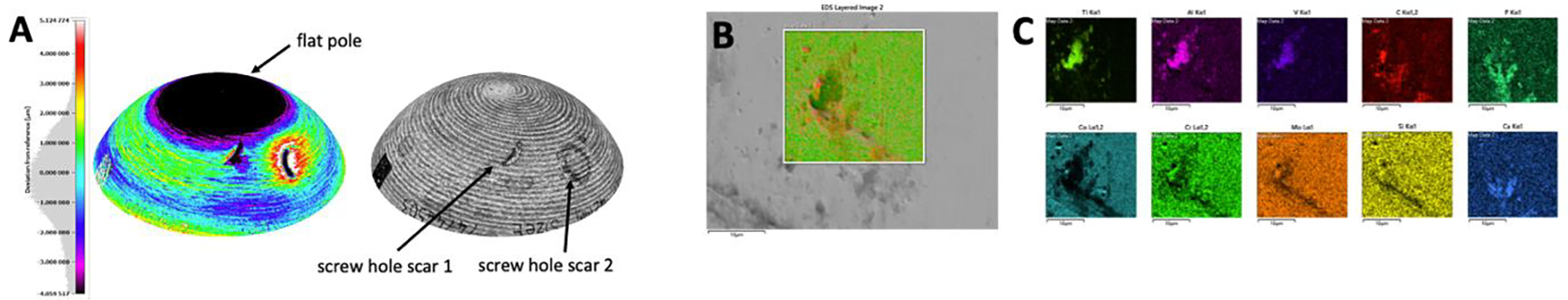
A) Heat map (left) and intensity map (right) of the dome area on the backside of a MDM liners with two screw hole scars associated with 0.029 mm3 (scar 1) and 0.022 mm3 (scar 2) of material loss. B) Scanning electron microscope (SEM) image of screw hole scar and C) energy dispersive X-ray spectroscopy (EDS) mapping revealing Ti6Al4V material transfer, as well as carbon, calcium and phosphorous rich organic deposits.
Malseating
There were seven liners (25%) that had radiographic evidence of malseating, and all were of the MDM design (P = 0.01). Malseated liners had a longer average time in situ compared to well-seated liners (36.1 ± 27.1 versus 7.25 ± 9.04 months, P = 0.031), a higher average mGS (3.3 ± 1 versus 2.0 ± 0.8, P = 0.012), volumetric material loss at the taper (0.29 ± 0.3 versus 0.008 ± 0.02 mm3, P <= 0.037), and maximum linear penetration at the taper (11.98 ± 16.5 μm versus 0.49 ± 1.7 μm, P = 0.006). Multivariate linear regression models were conducted to determine the impact of malseating and time in situ on mGS volumetric material loss and maximum linear penetration. In these models, time in situ correlated with mGS (coefficient = 0.26, P = 0.031), while malseating did not. However, malseating was an independent risk factor for increased volumetric material loss (coefficient = 0.2460 mm3, P = 0.008) and increased maximum linear penetration (coefficient = 10.67 μm, P = 0.048), while time in situ was not.
Differences in shape deviation, alloy microstructure, and material loss between designs
The CMM analysis revealed that most liners exhibited some degree of out-of-roundness (OOR) at the taper surface. In the case of the MDM design, OOR occurred always in a symmetrical fashion, while the G7 design exhibited a more random deviation of a circular shape (Figure 9). The MDM and G7 liners exhibited a fundamentally different initial surface morphology due to the finishing process applied during manufacturing. The MDM exhibited machining lines indicative of a milling process, while the G7 exhibited a roughened surface due to an apparent aluminum-oxide blast finish, as indicated by the presence of fine aluminum oxide particles within the surface topography. The metallographic analysis of each liner type revealed, based on the appearance of the alloy’s microstructure, that MDM and G7 liners were made from 4 mm thick wrought (ASTM F1537) and 3 mm thick cast (ASTM F75) CoCrMo alloy, respectively. The MDM exhibited a characteristic microstructure of a low carbon wrought alloy with fine grains (2 to 4μm) and no carbides, while the G7 liner exhibited large grains with a grain size of several hundred μm, and the presence of carbides along the grain boundaries.
Figure 9:
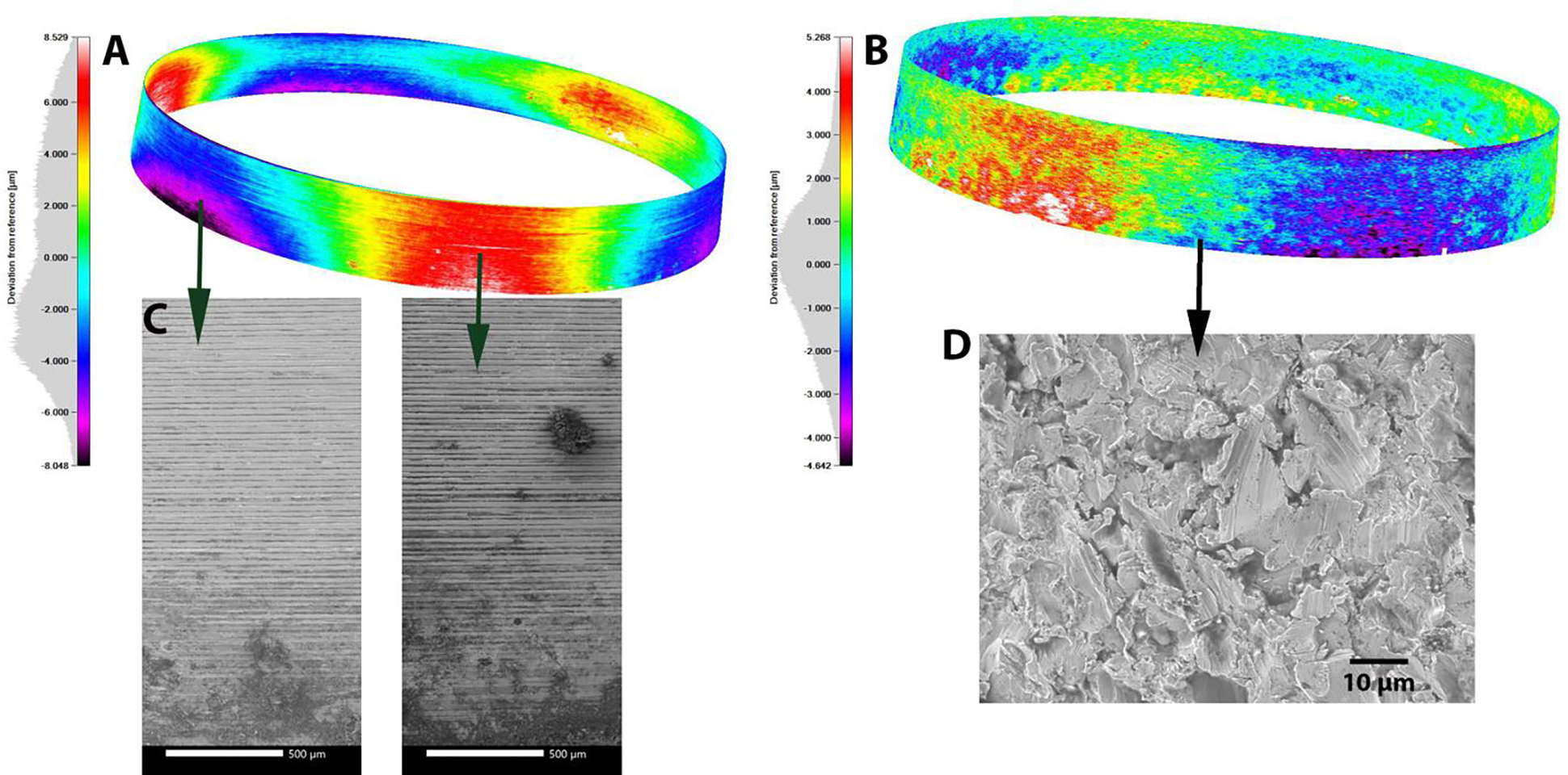
A) Typical heat map of a MDM liner with minimal damage and characteristic symmetrical out of roundness and B) heat map of a G7 liner with asymmetric out of roundness. C) Scanning electron microscope (SEM) images of the original surface topography of an MDM liner in area that were unlikely and likely in contact with the corresponding cup due to out of roundness. No difference was observed in both cases. D) The typical surface topography of G7 liners was indicative of a sandblasting or a similar technique.
When comparing the MDM and G7 implants, there were no significant differences in average mGS (2.50 ± 1.21 versus 2.11 ± 0.61, P = 0.84) and maximum linear penetration (5.80 ± 11.96μm versus 0.00 ± μm, P = 0.073). However, MDM liners were implanted longer (20.26 ± 23.8 versus 6.59 ± 7.34 months, P = 0.049) and exhibited more volumetric material loss (0.134 ± 0.22 versus 0.00 mm3, P = 0.031) at the taper than G7 liners. There was a higher incidence of malseating among the MDM liners compared to the G7 liners (44 versus 0%, P = 0.01).
DISCUSSION
Modular DM implants for primary and revision THA have gained popularity given the lower rates of postoperative instability; however, the risks of liner malseating and the tribocorrosion properties of the contact areas between the liner and acetabular shell must be considered. To our knowledge, this is the first series to evaluate how liner malseating and implant design features affect qualitative corrosion patterns and quantitative material loss on the backside taper in two different modular DM designs. This investigation found that liner backside tribocorrosion with quantifiable material loss occurred more commonly in malseated liners and only at the taper surface. However, not all malseated cases exhibited tribocorrosion. Specific design characteristics may make liners more prone to malseating, and the interplay between seating mechanics, liner characteristics, and patient factors likely contributes to the backside taper tribocorrosion environment. Additionally, this study also found that the use of a modified Goldberg score could lead to a gross overestimation of the presence of fretting and corrosion damage at the backside of DM THA liners and needs to be applied with caution.
Malseating was found to be an independent risk factor for increased volumetric material loss and maximum linear penetration at the taper. Liner malseating in dual mobility implants is a well-described phenomenon, and multiple in vitro models have attempted to replicate the impact that malseating has on fretting and corrosion currents [6, 19]. The model of Romero et al, which included both mechanically loaded malseated and well-seated liners, found that malseated liners demonstrated earlier fretting current onset at lower peak loads compared with well-seated liners. The present investigation is the first to show that malseating of the liner may increase the risk of tribocorrosion and material loss in vivo. Tribocorrosion with quantifiable material loss occurred only in malseated cases. Malseating may result in lack of full taper engagement, potentially increasing the propensity for micromotion and, therefore, fretting. Additionally, malseating may enable additional fluid infiltration into the taper interface and promote crevice corrosion or other chemical degradation processes [17]. The occurrence of chemical corrosion in a non-contact area supports this assumption. While large clinical studies have found that the incidence of radiographic liner malseating is low and does not lead to increased revision risk [5, 6], our analysis suggests that a well aligned taper is unlikely to experience tribocorrosion, whereas a malseated taper is at risk. However, the exact clinical sequalae of malseated liners is not well understood at the present time.
A variety of chemical, mechanical, and combined tribocorrosion patterns were seen on the liner tapers, however, this was not always accurately portrayed by the mGS designation. Of the implants analyzed, 40% exhibited moderate or severe corrosion based on mGS, yet several of these liners did not have quantifiable material loss. The mGS is based on evaluation by lower power light microscopy. On the G7 liner tapers and G7/MDM domes, light microscope evaluation identified deposits that appeared characteristic of imprinting and thus resulted in an elevated mGS for the retrieved specimen. However, upon further evaluation with SEM, these areas only exhibited organic deposits of fibrinous tissue. While the mGS provides a useful overall indication of the possible degree of damage, it is not effective in identifying modes of damage, such as distinguishing fretting and corrosion or predicting material loss quantitatively at low magnification levels [10, 20]. Kolz et al. analyzed one of the DM liner designs evaluated in the current study and found similar qualitative corrosion scores (average mGS 2.7 ± 0.9 versus 2.5 ± 1.2); however, the observed maximum linear penetration depth in that study was significantly higher (35.5 versus 5.80 μm). The mGS values in this and other studies should be considered in the context of specific corrosion and material loss analysis; otherwise, misidentification of the occurrence and severity of surface damage is a risk. It also has to be taken into account that, in comparison to the MDM liner, the G7 backside surface has a rougher surface finish due to the aluminum-oxide blasting process. Optical scoring may be inherently biased because of the differences between these two surfaces. With respect to damage to the dome area of the liner backside, we were not able to confirm a previous report of prevalent corrosion of the same liner designs [15]. Here, we quantified damage at the dome based on CMM data and only found material loss in two cases of each design due to contact with the titanium alloy screw heads. However, this damage was not corrosion related.
Shape deviation and alloy microstructure differed between liner designs and may affect liner seating mechanics and the tribocorrosion environment. The two liner designs were fundamentally different from one another with respect to the CoCrMo alloy type, taper surface finish, and shape deviations (OOR). These metallurgy differences, combined with design distinctions such as the larger wall thickness of the MDM (4 mm) cup compared to the G7 (3 mm), make a direct comparison of tribocorrosion processes of these two implants difficult. However, our findings provide important insights into the seating and tribocorrosion behavior of each individual liner type.
The MDM liner exhibited a symmetrical OOR to varying degrees that is likely introduced during the machining process. The fact that these retrieved components exhibit symmetric OOR indicates that the liners did not deform markedly during implantation or removal. Certain characteristics, such as increased wall thickness and wrought CoCrMo alloy with fine grain size, contribute to the stiffness of the liner, making it more resistant to deformation [21]. This liner stiffness and OOR may increase the risk of malseating, however, as it could impede the bedding-in behavior of the liner into the corresponding cup.
There were five cases of severe and two cases of moderate tribocorrosion seen in MDM liners, and four liners had a maximum linear penetration of > 7 μm. This threshold has been previously established as potentially clinically relevant with respect to ALTR-related failure in MoM bearings; however, no cases were specifically revised for ALTR in this series [10, 18]. Overall, the occurrence of tribocorrosion damage is consistent with previous retrieval studies of this same design. However, some of these retrieval analyses were confounded by modular neck femoral components [9, 10].
The G7 liner appeared to be manufactured by casting, and thus it is impossible to determine the initial shape of the liner. Malseating of a G7 liner was not identified in the current series. Based on the evaluation of liner geometry after explantation, it appears that G7 liners undergo plastic deformation during the seating and bedding-in process. This deformation may be enabled by the decreased wall thickness and the grain size of the cast alloy. As a result, liners did not exhibit evidence of micromotion and subsequent tribocorrosion. The severe deformation caused to the three G7 liners during explanation may also be an indicator of the robust fixation between the cup and liner. This finding also aligns with an earlier in vitro study demonstrating higher onset loads for G7 liners, while being more prone to corrosion once micromotion was initiated [15]. Our own previous work also indicated superior corrosion behavior of wrought versus cast CoCrMo alloys [21]. However, the results of the present study show that none of the G7 liners underwent mild plastic deformation during assembly, thereby avoiding malseating, micromotion, and the onset of tribocorrosion processes, despite the potential for slightly inferior corrosion resistance.
Potential Limitations
The findings presented here must be interpreted in the context of several potential limitations, the most important of which is the small number of analyzed implants. The small study size and the evidence of liner malseating in a single implant design limit the ability of statistical analysis to correlate specific implant factors or patient characteristics to the risk of tribocorrosion. A larger retrieval cohort is needed to evaluate the impact and synergism of multiple potential risk factors by means of multilinear regression models. Also, to determine liner malseating, a radiograph nearly parallel to the face of the acetabular component is required. Despite the high rate of liner malseating found in the present series (25%), inadequate radiographs or imperfect projection angles may have have led to underreporting of malseated liners. Additionally, the design of the G7 liner is such that it is inset within the acetabular shell, making it possible that a malseated liner may not always be visible radiographically. All implants were retrieved in revision THA, and the material loss characteristics may differ from those of well-functioning liners with no need for revision. Also, the observation of tribocorrosion does not establish a diagnosis of ALTR, and correlation with serum metal levels and the histopathology of periprosthetic tissues from patients from whom the implants had been retrieved was not possible in this cohort. While this is a limited sample size of only two implant designs, to our knowledge, this is the largest quantitative and radiographic investigation of modular DM acetabular liners.
Conclusions
In conclusion, we found that modular dual mobility liner malseating influences tribocorrosion patterns and rates of material loss. The CoCrMo liners across manufacturers can differ broadly in design, material, and surface finish, which may have implications for the malseating and tribocorrosion behavior of the liner. Alloy microstructure, gross design features, surgical technique, and patient factors should all be considered when using modular DM liners. Further research is needed to determine if tribocorrosion of the shell/liner junction secondary to liner malseating increases the risk of ALTR and clinical failure.
References:
- 1.Gwam CU, Mistry JB, Mohamed NS, Thomas M, Bigart KC, Mont MA, Delanois RE. Current Epidemiology of Revision Total Hip Arthroplasty in the United States: National Inpatient Sample 2009 to 2013. J Arthroplasty 32(7): 2088, 2017 [DOI] [PubMed] [Google Scholar]
- 2.Heckmann N, Weitzman DS, Jaffri H, Berry DJ, Springer BD, Lieberman JR. Trends in the use of dual mobility bearings in hip arthroplasty. Bone Joint J 102-b(7_Supple_B): 27, 2020 [DOI] [PubMed] [Google Scholar]
- 3.Rowan FE, Benjamin B, Pietrak JR, Haddad FS. Prevention of Dislocation After Total Hip Arthroplasty. J Arthroplasty 33(5): 1316, 2018 [DOI] [PubMed] [Google Scholar]
- 4.Nam D, Salih R, Nahhas CR, Barrack RL, Nunley RM. Is a modular dual mobility acetabulum a viable option for the young, active total hip arthroplasty patient? Bone Joint J 101-b(4): 365, 2019 [DOI] [PubMed] [Google Scholar]
- 5.Chalmers BP, Dubin J, Westrich GH. Modular Dual-Mobility Liner Malseating: A Radiographic Analysis. Arthroplast Today 6(4): 699, 2020 [DOI] [PMC free article] [PubMed] [Google Scholar]
- 6.Romero J, Wach A, Silberberg S, Chiu YF, Westrich G, Wright TM, Padgett DE. 2020 Otto Aufranc Award: Malseating of modular dual mobility liners. Bone Joint J 102-b(7_Supple_B): 20, 2020 [DOI] [PubMed] [Google Scholar]
- 7.Langdown AJ, Pickard RJ, Hobbs CM, Clarke HJ, Dalton DJ, Grover ML. Incomplete seating of the liner with the Trident acetabular system: a cause for concern? J Bone Joint Surg Br 89(3): 291, 2007 [DOI] [PubMed] [Google Scholar]
- 8.Miller AN, Su EP, Bostrom MP, Nestor BJ, Padgett DE. Incidence of ceramic liner malseating in Trident acetabular shell. Clin Orthop Relat Res 467(6): 1552, 2009 [DOI] [PMC free article] [PubMed] [Google Scholar]
- 9.Hemmerling KJ, Weitzler L, Bauer TW, Padgett DE, Wright TM. Fretting and corrosion of metal liners from modular dual mobility constructs : a retrieval analysis. Bone Joint J 103-b(7): 1238, 2021 [DOI] [PubMed] [Google Scholar]
- 10.Kolz JM, Wyles CC, Van Citters DW, Chapman RM, Trousdale RT, Berry DJ. In Vivo Corrosion of Modular Dual-Mobility Implants: A Retrieval Study. J Arthroplasty 35(11): 3326, 2020 [DOI] [PubMed] [Google Scholar]
- 11.Carli A, Politis A, Zukor D, Huk O, Antoniou J. Clinically significant corrosion at the head-neck taper interface in total hip arthroplasty: a systematic review and case series. Hip Int 25(1): 7, 2015 [DOI] [PubMed] [Google Scholar]
- 12.Gilbert JL, Buckley CA, Jacobs JJ. In vivo corrosion of modular hip prosthesis components in mixed and similar metal combinations. The effect of crevice, stress, motion, and alloy coupling. J Biomed Mater Res 27(12): 1533, 1993 [DOI] [PubMed] [Google Scholar]
- 13.Matsen Ko LJ, Pollag KE, Yoo JY, Sharkey PF. Serum Metal Ion Levels Following Total Hip Arthroplasty With Modular Dual Mobility Components. J Arthroplasty 31(1): 186, 2016 [DOI] [PubMed] [Google Scholar]
- 14.Ilo KC, Derby EJ, Whittaker RK, Blunn GW, Skinner JA, Hart AJ. Fretting and Corrosion Between a Metal Shell and Metal Liner May Explain the High Rate of Failure of R3 Modular Metal-on-Metal Hips. J Arthroplasty 32(5): 1679, 2017 [DOI] [PubMed] [Google Scholar]
- 15.Steele JR, Shenoy AA, Pekmezian A, Wright T, Padgett DE. Evaluation of Mechanically-Assisted Crevice Corrosion of Different Modular Dual Mobility Constructs. J Arthroplasty 38(7s): S274, 2023 [DOI] [PMC free article] [PubMed] [Google Scholar]
- 16.Goldberg JR, Gilbert JL, Jacobs JJ, Bauer TW, Paprosky W, Leurgans S. A multicenter retrieval study of the taper interfaces of modular hip prostheses. Clin Orthop Relat Res (401): 149, 2002 [DOI] [PubMed] [Google Scholar]
- 17.Hall DJ, Pourzal R, Lundberg HJ, Mathew MT, Jacobs JJ, Urban RM. Mechanical, chemical and biological damage modes within head-neck tapers of CoCrMo and Ti6Al4V contemporary hip replacements. J Biomed Mater Res B Appl Biomater 106(5): 1672, 2018 [DOI] [PMC free article] [PubMed] [Google Scholar]
- 18.Lanting BA, Teeter MG, Howard JL, MacDonald SJ, Van Citters DW. Metal-on-Metal Compared With Metal-on-Polyethylene: The Effect on Trunnion Corrosion in Total Hip Arthroplasty. J Arthroplasty 32(8): 2574, 2017 [DOI] [PubMed] [Google Scholar]
- 19.Shenoy AA, Gilbert JL. In vitro test methods for seating and fretting corrosion behavior of modular metal-on-metal acetabular tapers. J Orthop Res 38(5): 1089, 2020 [DOI] [PubMed] [Google Scholar]
- 20.Agne MT, Underwood RJ, Kocagoz SB, MacDonald DW, Day JS, Parvizi J, Kraay MJ, Mont MA, Klein GR, Cates HE, Kurtz SM. Is there material loss at the backside taper in modular CoCr acetabular liners? Clin Orthop Relat Res 473(1): 275, 2015 [DOI] [PMC free article] [PubMed] [Google Scholar]
- 21.Pourzal R, Hall DJ, Ehrich J, McCarthy SM, Mathew MT, Jacobs JJ, Urban RM. Alloy Microstructure Dictates Corrosion Modes in THA Modular Junctions. Clin Orthop Relat Res 475(12): 3026, 2017 [DOI] [PMC free article] [PubMed] [Google Scholar]