

Abstract
The drag of the net is the main component of the total hydrodynamic loads on the cage. It is crucial to the operational safety and structural integrity of the net cage. Despite this, there is a paucity of research examining the impact of various parameters, including materials, mesh types, solidity ratios, and angles of attack, on the hydrodynamic loads of nets. In this paper, a series of flume tests are used to investigate the drag on the nets and the relationships between the drag coefficient and the net material, net solidity ratio, mesh shape, current velocity, and current direction. The drag of six nets with different types under varying current velocities and current directions are calculated, and the curves between the drag coefficient and the current velocity or Reynolds number are further obtained. The test results show that the drag and drag coefficients of the net are not only related to the current velocity and the windward area but also to the mesh shape, net solidity ratio, material properties, etc. On this basis, the drag coefficients of these nets obtained from the prediction models and the tests are compared and analyzed, and the applicable conditions of different prediction models are further clarified. This paper can provide data support for the drag calculation of the cage.
Supplementary Information
The online version contains supplementary material available at 10.1038/s41598-025-99615-3.
Keywords: Net, Drag, Drag coefficients, Flume test
Subject terms: Hydrology, Ocean sciences, Engineering
Introduction
Aquaculture is a globally sustainable industry that provides food and bioenergy to the world’s growing population1. Global consumption of aquatic foods (excluding algae) increased at an average annual rate of 3.0% from 1961 to 2019, a rate almost twice that of annual world population growth (1.6%) for the same period2. Notably, in 2020, Asian countries were the main producers accounting for 70% of the total, followed by the Americas, Europe, Africa, and Oceania. China remained the first major producer with a share of 35% of the total.
As one of the representative aquaculture methods, net cage culture is widely used in the global aquaculture industry3. For the traditional net cage, the hydrodynamic forces on the nets account for about 85% of the hydrodynamic forces on the overall structure4. Extensive research has also demonstrated that the force exerted on nets is proportional to the square of the flow velocity, indicating that minor variations in velocity can result in substantial differences in force5. Consequently, comprehending the interaction between nets and ocean currents is of paramount importance, which is related to ensuring the safety and applicability of cage design.
Aquaculture nets, predominantly situated beneath the water surface, are subjected to substantial current loads. The key physical factors to be considered are water depth, current velocity, near-field circulation, dissolved oxygen, and the solidity of the nets6. The flow regime inside cages depends on the inflowing current, the interaction of the current with the net structure7, and the effects of the fish and their behavior8,9. The flow regime can also be subdivided into two parts: flow through the net mesh and flow around the net wire, depending on the hydrodynamics1. Therefore, the effects of various factors must be conducted to comprehensively understand the changing characteristics of hydrodynamic loads on the nets.
Over the past few decades, extensive experimental investigations have been conducted to enhance our understanding of the hydrodynamic loads on nets. Taylor et al.(1944) introduced the relative turbulence intensity method to analyze the wake behind screens and proposed a prediction for the drag coefficient (Cd) as a function of screen solidity10. Regarding the impact of solidity ratio on net drag, Lader et al. (2007) found that varying solidity ratios significantly influenced net drag, which increased with higher solidity ratios11. In terms of biofouling effects, Milne et al.12 concluded that the drag force on a biofouled net was nearly double that of a clean net12, which was also found by Bi et al. (2018), who identified dominant biofouling on nets and examined the drag associated with fouled nets, revealing that the hydrodynamic load could increase by over tenfold compared to clean nets13. Focusing on different mesh types, while most of the aforementioned studies focused on square mesh types, Zhan et al.14 conducted multiple towing tank experiments on diamond mesh patterns, deriving analytical formulas for the total normal drag on planar and cylindrical nets14. Tsukrov et al. (2011) experimentally investigated the drag on copper alloy nets, demonstrating significantly lower resistance to currents and lower drag coefficient values for these nets15.
Concerning the hydrodynamic coefficients of various net materials and structures, Dong et al. (2021) studied the hydrodynamic coefficients of polyethylene (PE) flat nets across different wire diameters and mesh sizes, as well as chain link wire flat nets16. Tang et al. (2018) performed experimental analyses on six groups of net panels with varying materials, mesh densities, and node shapes based on flume tests17. They introduced the concept of cross elements to calculate hydrodynamic loads and thoroughly discussed the effects of mesh density, material, node shape, and Reynolds number on the hydrodynamic coefficients of the net panels. Huang and Shao (2019) conducted physical simulations on flat nets made of polyethylene (PE) and polyamide (PA) to study their deceleration performance and wake characteristics18. Regarding the influence of angle of attack and flow velocity on net drag, Wu et al. (2024) performed hydrodynamic tests on four rigid net panels in a flume, varying the angle of attack (0° to 90°) and flow velocity (0.3 to 1.2 m/s)19. They found significant variation in the drag coefficient of woven net panels, ranging from 0.13 to 1.26. The turtle shell net panel exhibited the lowest drag coefficient when perpendicular to the flow and the highest when parallel. Zhao et al. (2024) examined the hydrodynamic behavior of ultra-high molecular weight polyethylene (UHMWPE) planar nets and the surrounding flow field, noting that increased flow velocity led to a smaller reduction in flow speed along the net’s horizontal centerline20. However, larger angles of attack and higher densities resulted in a greater reduction in flow speed. Investigating the hydrodynamic characteristics of fouled nets under special working conditions, Li et al. (2024) conducted a study using flume experiments and large eddy simulation (LES) numerical methods to investigate the hydrodynamic characteristics and surrounding flow field of fouled net panels21. The results indicated that at the same level of contamination, a net contaminated with shell aggregates experiences greater drag compared to a net contaminated with bio-accumulation. This finding highlights the significant impact of different types of fouling on the hydrodynamic performance of nets.
Despite the extensive experiments conducted on net drag, a significant gap remains in understanding the applicability of various prediction models for load estimation as reported in the literature. Many existing studies focus on specific parameters without thoroughly evaluating how these models can be generalized to different conditions and materials. This lack of comprehensive assessment hinders the development of reliable prediction tools that can be utilized in practical applications. To address this gap, this paper employs flume tests to systematically investigate the drag forces experienced by nets under controlled conditions. By varying critical factors such as net materials, solidity ratios, mesh shapes, current velocities, and current directions, we aim to establish a clearer understanding of how these variables influence drag coefficients. This approach not only seeks to quantify the relationships between these factors and drag but also aims to validate and refine existing prediction models. Ultimately, our goal is to contribute to improved design and performance evaluation of nets in various hydrodynamic environments.
Geometry, structure and model of nets
Aquaculture cages utilize a variety of nets, categorized as rigid and flexible based on their rigidity22. Rigid nets are made from materials such as copper, copper-nickel, copper-silicon, and steel, while flexible nets are composed of nylon and polyethylene (PE). Additionally, nets are classified by mesh shape into diamond and square configurations. Given the widespread use of various net types in marine aquaculture, we selected six net types for hydrodynamic performance comparison (Fig. 1). The list of nets investigated is provided in Table 1.
Fig. 1.

Six types of nets. (a) diamond-copper N1, (b) diamond-steel N2, (c) square-nylon N3, (d) square-steel N4, (e) square-steel N5, (f) square-PE N6.
Table 1.
The characteristics of the net models.
| Net model | Mesh shape | Net material | Twine diameter dw (mm) | Twine length lw (mm) | Mesh tension angle 2θ (°) | Net solidity Sn |
|---|---|---|---|---|---|---|
| N1 | Diamond | Copper | 3 | 25 | 45 | 0.31 |
| N2 | Diamond | Steel | 1.5 | 11 | 60 | 0.29 |
| N3 | Square | Nylon | 2.52 | 20 | – | 0.24 |
| N4 | Square | Steel | 2 | 13 | – | 0.28 |
| N5 | Square | Steel | 1.3 | 14.5 | – | 0.17 |
| N6 | Square | PE | 1.6 | 17.4 | – | 0.17 |
The hydrodynamic characteristics of the net are closely related to the Solidity Ratio (Sn), which is defined as the ratio of the projected area Ap to the outline area A of the whole net:
 |
1 |
There is a subtle difference in the methods for calculating the solidity ratio between square-mesh and diamond-mesh netting; the geometric parameters for these two types of nets are illustrated in Fig. 2.
Fig. 2.

Geometric parameters of nets. (a) diamond-mesh net, (b) square-mesh net.
For the square mesh net (Fig. 2a), the formula can be simplified as:
 |
2 |
where dw and lw are the twine diameter and twine length, respectively.
For the diamond mesh net (Fig. 2b), Fredheim (2005) calculated Sn for the diamond net using Hang Ratios E1 and E27.
 |
3 |
where E1 and E2 are related to the shape of the diamond mesh, and they are a function of the mesh tension angle 2θ, which can be expressed as:
 |
4 |
 |
5 |
where NH and NV are the numbers of mesh in the horizontal and vertical directions of the nets respectively.
The Hydrodynamic characteristics of nets are also related to the angle of attack (AOA), which is defined as the residual angle between the flow direction and the angle normal to the direction of the nets, as shown in Fig. 3:
Fig. 3.

Definition of the angle of attack (AOA).
Experimental setup
In this study, we conducted a series of experiments to investigate the hydrodynamic loads on various types of aquaculture nets. The experiments were designed to simulate the conditions under which these nets operate in real-world scenarios. However, it is important to note that the experiments were quasi-static in nature, rather than fully dynamic. This means that the nets were subjected to controlled, gradual changes in flow conditions, rather than the rapid, unsteady flows that might be encountered in some hydrodynamic environments.
The hydrodynamic experiments were carried out in the current flume tank (the overall dimensions:7.0 m in length, 1.7 m in width, 1.8 m in height, with a water depth of 1.5 m, and current flow velocities range of 0.3 m/s ~ 2.0 m/s) located at Science and Technology on Underwater Vehicle Laboratory, Harbin Engineering University, Harbin, China. The velocities can be changed by a pump, which can generate different rotation frequencies. The coordinate system satisfies a right-handed Cartesian coordinate system, where the x is positive along the flow direction, y is perpendicular to the flow direction, and z is vertically upward. The arrangement of the experimental apparatus is shown as Fig. 4.
Fig. 4.

Arrangement of experimental apparatus. (a) general view of the entire apparatus, (b) pictures of the apparatus, (c) pictures of the three-dimensional load sensor.
Subsequently, the net panel was stretched on a square frame structure, which can reduce the deformation of nets caused by the current flow. The rod at the top of the frame is fixed to the connector by bolts. The drag on the frame and net induced by current were measured by a three-dimensional load sensor in Fig. 4c (± 0.2% Full Scale, ranging from 0 ~ 1000 N), which can measure the loads on the net in three directions, Fx, Fy, and Fz, where Fx is the load along the flow direction, Fy is the load perpendicular to the flow direction and Fz is the vertical load. During the test, the focus is on the load Fx, which is the normal drag.
Two angles were set to investigate the effect of AOA on the loads for the net, AOA = 90° (vertical) and AOA = 45° (inclined), respectively. The net was completely submerged, the center of the net was 0.75 m from the water surface and both sides were 0.6 m from the wall of the flume, which could effectively avoid the interference of the water surface and pool wall effects on the measurement.
The experimental process is as follows:
-
(i)
Calibrate the three-dimensional loads sensor. The load sensor measured the force of 1 kg weight as 9.82 N, while the local acceleration of gravity was 9.81 N/kg. The difference between them was < 0.01, which means the calibration was successful.
-
(ii)
Generate current with distinct velocities. The minimum flow velocity that can be generated by the flume is 0.3 m/s. The flow velocities of 0.3 m/s, 0.5 m/s, 0.75 m/s, 1.0 m/s, 1.25 m/s, and 1.5 m/s were generated by changing the pump frequency. After each measurement, 5 ~ 10 min were waited to eliminate the free surface fluctuation to reduce the interference to the experiment data.
-
(iii)
After the test data were recorded, the subsequent data processing was performed.
Figure 5 illustrates the variations in total drag (combined drag of the net panel and frame) and frame drag over a time series for the N1 net panel at 1.0 m/s. The AOA = 90° (vertical) and AOA = 45° (inclined) are considered. The plot demonstrates a consistent and stable trend over time for both the total drag and the frame drag, affirming the reliability of the experimental data acquired in this study. The frame drag is deducted from the total drag to determine the force acting on the net panel. The frame-drag to total-drag ratio is approximately 24.7% for the AOA = 90° and 27.5% for the AOA = 45°.
Fig. 5.

The drag force on the diamond-copper N1 (Sn = 0.31) nets with time series at u = 1.0 m/s in the experiment: (a) AOA = 90◦, (b) AOA = 45°.
Result and discussion
Analysis of drag on nets
During the test, we measured the hydrodynamic forces on a frame both with and without a net. The drag force was calculated as the difference between these measurements. The forces exerted on the nets at various angles of attack (AOA) and flow velocities are presented in Table 2; Fig. 6.
Table 2.
Drag on Nets at different velocities and AOAs/N.
| U∞ (m/s) | Net model | |||||||||||
|---|---|---|---|---|---|---|---|---|---|---|---|---|
| N1 (Sn=0.31) | N2 (Sn=0.29) | N3 (Sn=0.24) | N4 (Sn=0.28) | N5 (Sn=0.17) | N6 (Sn=0.17) | |||||||
| 90° | 45° | 90° | 45° | 90° | 45° | 90° | 45° | 90° | 45° | 90° | 45° | |
| 0.30 | 5.67 | 3.43 | 5.73 | 3.10 | 3.87 | 2.35 | 3.91 | 2.37 | 2.12 | 1.40 | 2.08 | 1.29 |
| 0.50 | 15.68 | 9.12 | 16.03 | 8.22 | 10.69 | 6.18 | 10.35 | 6.11 | 5.58 | 3.45 | 5.41 | 3.09 |
| 0.75 | 35.27 | 18.28 | 36.53 | 19.01 | 23.44 | 14.23 | 22.39 | 13.90 | 12.45 | 7.90 | 12.01 | 7.27 |
| 1.00 | 60.91 | 32.47 | 63.12 | 31.82 | 38.90 | 25.52 | 38.08 | 24.84 | 20.14 | 14.23 | 20.05 | 13.46 |
| 1.25 | 94.44 | 48.97 | 97.75 | 48.42 | 58.86 | 37.35 | 59.48 | 36.79 | 31.94 | 21.79 | 32.08 | 20.37 |
| 1.50 | 140.97 | 68.43 | 140.87 | 68.47 | 82.16 | 52.28 | 85.13 | 52.15 | 44.50 | 31.97 | 45.82 | 28.09 |
Fig. 6.

The correlation between drag and velocities on nets. (a) AOA = 90°, (b) AOA = 45°.
Figure 6 delineates the quadratic relationship between net force and flow velocity, highlighting increased drag with higher flow speeds. Diamond-shaped nets, such as N2, exhibit significantly higher drag—1.5 to 1.7 times that of square-shaped nets like N4—even with similar solidity ratios and materials. This is consistent with Qu et al.‘s (2019) findings that diamond-mesh nets experience 1.6 times the drag of square-mesh nets23. Solidity ratio exerts a more pronounced influence on drag than material type, as seen in the negligible drag difference between copper N1 and steel N2, and the near overlap of drag curves for steel N5 and PE N6. The nylon N3, despite a 14% lower solidity than N4, shows only a 0.6% force difference, indicating increased drag due to its flexibility and potential for deformation under current, as illustrated in Fig. 7.
Fig. 7.
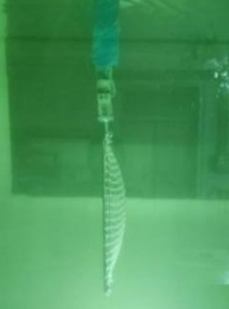
Deformation of N3 with nylon material (U∞=1.0 m/s).
The angle of attack (AOA) emerges as one of the most influential factors on drag. Reducing AOA from 90° to 45° leads to a substantial reduction in drag: approximately 50% for diamond-mesh nets (N1 and N2) and 25–35% for square-mesh nets (N3, N4, N5, and N6). This decrease in AOA reduces the effective flow area, modifies the flow pattern, and extends the wake region with lower velocity, thereby decreasing the overall drag coefficient. The impact of AOA on the drag coefficient is attributed to its role in determining the effective flow area and velocity distribution around the net. A lower AOA presents a smaller frontal area to the flow, reducing drag force and delaying flow separation, which enlarges the wake region and further lowers the drag coefficient. The extent of this reduction varies with mesh shape, as different shapes influence flow separation points and wake region size, affecting the drag coefficient to varying degrees.
In summary, net drag is influenced not only by flow velocity but also by mesh shape, solidity, material, and angle of attack. The drag on diamond-mesh nets is 1.5 to 1.7 times greater than on square-mesh nets. Nets with higher angles of attack and solidity experience increased fluid loads, enhancing drag. Additionally, nylon material may increase drag due to net deformation under current and the expansion of the turbulence region around the net twine. Nylon’s flexibility increases susceptibility to deformation by water currents, enlarging the wetted surface area and enhancing drag force. This deformation alters the net’s interaction with surrounding water, potentially causing more significant flow disruption. It can be clearly seen in Fig. 6 that the nylon net has undergone significant deformation. The expansion of the turbulence region around the net twine is another critical factor, as water flow past the net creates vortices and eddies, particularly when separating from the net strands24. This turbulence, exacerbated by nylon net deformation, affects a larger area, increasing drag force. Increased turbulence can also impose additional stress on the net material, leading to wear and tear over time. The combined effects of net deformation and turbulence expansion significantly influence the hydrodynamic loads on the net, with deformation increasing the wetted surface area and turbulence region, leading to greater pressure differences across the net and increased drag force.
Analysis of drag coefficients on nets
The drag coefficients for nets at angles of attack (AOA) of 90°and 45°across various flow velocities are detailed in Table 3, while the correlation between drag coefficients and flow velocities is depicted in Fig. 8. Additionally, the drag coefficients were derived based on the Morison equation25.
Table 3.
Drag coefficients on Nets at different velocities and AOAs.
| U∞ (m/s) | Net model | |||||||||||
|---|---|---|---|---|---|---|---|---|---|---|---|---|
| N1 (Sn=0.31) | N2 (Sn=0.29) | N3 (Sn=0.24) | N4 (Sn=0.28) | N5 (Sn=0.17) | N6 (Sn=0.17) | |||||||
| 90° | 45° | 90° | 45° | 90° | 45° | 90° | 45° | 90° | 45° | 90° | 45° | |
| 0.30 | 1.716 | 1.467 | 1.853 | 1.400 | 1.504 | 1.290 | 1.302 | 1.118 | 1.145 | 1.082 | 1.130 | 0.999 |
| 0.50 | 1.644 | 1.347 | 1.790 | 1.303 | 1.442 | 1.180 | 1.202 | 1.000 | 1.063 | 0.929 | 1.035 | 0.832 |
| 0.75 | 1.618 | 1.190 | 1.791 | 1.322 | 1.392 | 1.193 | 1.140 | 1.001 | 1.044 | 0.947 | 1.007 | 0.858 |
| 1.00 | 1.565 | 1.178 | 1.730 | 1.236 | 1.288 | 1.196 | 1.081 | 0.998 | 0.941 | 0.942 | 0.939 | 0.892 |
| 1.25 | 1.544 | 1.135 | 1.709 | 1.198 | 1.245 | 1.116 | 1.078 | 0.942 | 0.954 | 0.920 | 0.958 | 0.859 |
| 1.50 | 1.599 | 1.098 | 1.722 | 1.175 | 1.204 | 1.084 | 1.069 | 0.927 | 0.920 | 0.936 | 0.948 | 0.822 |
Fig. 8.

The correlation between drag coefficients and flow velocities (a) AOA = 90°, (b) AOA = 45°.
Figure 8; Table 3 illustrate the relationship between drag coefficients and velocities for nets. The drag coefficient decreases with increasing flow velocity, stabilizing at a certain point. For diamond-mesh nets, it ranges from 1.5 to 1.75, while for square-mesh nets, it is between 1.0 and 1.5. Diamond-mesh nets exhibit higher drag coefficients than square-mesh nets under the same solidity and material conditions. For instance, N2’s drag coefficient (CD) is on average 35.2% greater than N4’s across various flow velocities. The possible explanations for the different CD of diamond/square-mesh nets are (i) the wake behind the two mesh-type nets are different, resulting in various drag forces26. (ii) the reconfiguration of square-mesh net causes drag reduction27.(iii)The effect of the solidity on the drag coefficient is related to the mesh shape of nets. The CD of the diamond-mesh net decreases with the increase of solidity, such as N1 and N2 in Fig. 5a; but the CD of the square-mesh net increases with the increase of solidity, such as N4 and N5.
N3’s nylon material results in a higher drag coefficient compared to the steel of N5 and the polyethylene of N6. Flexible materials like nylon lead to greater CD values due to deformation under current and increased surface roughness-induced turbulence. Additionally, the drag coefficient does not solely decrease with flow velocity; it can increase at specific velocities, especially when the angle of attack (AOA) is 45°. Therefore, it can be concluded that: (i) the net drag coefficient decreases alongside the velocity of flow only when the angle of attack is 90°. (ii) the drag coefficient of a diamond-mesh net is greater than that of a square-mesh net. (iii) the effect of the solidity on the drag coefficient is related to the mesh shape of nets. (iv) the angle of attack significantly affects the drag coefficient of the nets. When the angle of attack is reduced, the drag coefficient of the net decreases and the magnitude of the reduction is related to the net mesh shape.
Analysis of applicable conditions of models for load prediction
We selected multiple established models to predict the drag coefficients of netting and assessed their predictive accuracy. The models encompass those for diamond-mesh netting, as detailed by Zhan et al.14, and for square-mesh netting, which include the contributions from Milne et al.12, Aarsnes et al.28, DeCew et al.29, and Balash et al.30. The detailed computational approaches for these netting prediction models are outlined in the Appendix. A comparison between experimental data and the prediction model for loads on diamond- and square-mesh nets is presented in Fig. 9.
Fig. 9.

Comparison of drag coefficients and Reynolds numbers of nets (experimental data vs. predictions model). (a) diamond-copper N1, (b) diamond-steel N2, (c) square-nylon N3, (d) square-steel N4, (e) square-steel N5, (f) square-PE N6.
In Fig. 9, we evaluated the applicability of different prediction models by comparing the errors between experimental data and predicted values. The prediction model by Zhan et al.14 was derived from tests on HDPE net cages and three different solidity ratios of diamond-shaped nets (0.128, 0.215, 0.323) within a Reynolds number range of 174 to 1400. We observed that the drag coefficient (CD) predicted by Zhan’s model decreases with increasing Reynolds number (Re), contrasting with experimental data showing a slight increase at high Re values (Re > 2000). This divergence mirrors the behavior of a circular cylinder, where CD decreases as Re increases due to the transition from viscous to inertial forces. At low Re, the nets impede fluid motion due to dominant viscous forces, resulting in a higher CD. At high Re, the influence of inertial forces leads to more turbulent flow and a reduced CD as fluid around the nets increases. Additionally, the model’s predictions of CD at varying net solidities deviate from experimental results, with a tendency to overestimate at higher solidities and underestimate at lower solidities. For example, the errors for N1 and N2 across different flow velocities ranged from 1.0 to 16% and 2.0–8.9%, respectively. On average, the model overestimated CD by 2.83% for N1 (solidity ratio Sn = 0.31) and underestimated it by 1.98% for N2 (Sn = 0.29).
The prediction models by Balash et al.30 and Milne12 were based on nylon nets. For nylon nets (N3, Sn = 0.24), the drag coefficients predicted by Balash et al.30 and Milne12 had error ranges of 0.8–10.1% and 2.4–12.2%, respectively, compared to experimental data. Notably, Balash’s model accounts for the Reynolds number (Re), a factor not considered in Milne’s model.
The prediction models by Aarsnes et al.28 and Decew et al.29 were based on metal nets. For steel nets (N4, Sn = 0.28), DeCew’s model was the only one that closely aligned with experimental values, with a relative error of 2.0–9.1%. In contrast, the relative average error for Aarsnes’ model was 51%. DeCew’s model demonstrated superior accuracy in predicting the drag coefficient for metal meshes, also considering the influence of Re.
When the solidity ratio (Sn) is less than 0.2, the prediction models by Aarsnes et al.28 and Decew et al.29 showed average relative errors of 18% and 22% for N5, and 19% and 22% for N6, respectively. Only Aarsnes et al.‘s28 model had errors below 20%.
We have determined the applicable conditions for various prediction models, as summarized in Table 4. It is evident that no single model accurately predicts the drag coefficient for all net types. The model by Zhan et al.14 effectively estimates the drag coefficient for diamond nets within a Reynolds number range of 400 to 2000, considering both Re and solidity ratio. For square-mesh nets with nylon and intermediate solidities (0.2 < Sn < 0.8), the models by Balash et al.30 and Milne12 offer greater accuracy. In contrast, the model by Decew et al.29 is more suitable for steel material nets. For square-mesh nets with Sn < 0.2, only the model by Aarsnes et al.28 yields errors below 20%, making other models impractical due to excessive errors.
Table 4.
Applicable conditions of the prediction model.
| Applicable conditions | ||||
|---|---|---|---|---|
| Mesh shape | Material | Sn | Re | |
| Zhan. | Diamond | Copper/Steel | – | 400<Re<2000 |
| Aarsnes. | Square | Steel | Sn<0.20 | – |
| Balash. | Nylon | Sn>0.20 | 500<Re<4000 | |
| Decew. | Steel | Sn>0.20 | 500<Re<3000 | |
| Milne | Nylon | 0.2< Sn<0.8 | – | |
Conclusion
This study provides a comprehensive evaluation of various drag coefficient prediction models for different types of aquaculture nets. The key findings and conclusions are as follows:
The Zhan et al.14 model is effective for predicting the drag coefficient of diamond nets within a Reynolds number range of 400 to 2000, considering both the Reynolds number (Re) and solidity ratio (Sn). It accurately estimates the drag coefficient for diamond nets, which is crucial for understanding the hydrodynamic behavior of these nets in moderate flow conditions.The Balash et al.30 and Milne12 models are more accurate for square-mesh nets made of nylon with intermediate solidity ratios (0.2 < Sn < 0.8). They provide reliable predictions for the drag coefficient, which is essential for the design and operation of aquaculture nets in environments with moderate to high solidity ratios.The DeCew et al.29 model is the most suitable for steel nets, demonstrating high accuracy in predicting the drag coefficient. It is particularly useful for metal meshes, where the influence of Reynolds number (Re) is significant. The Aarsnes et al.28 model is the only one that yields errors below 20% for square-mesh nets with a solidity ratio (Sn) less than 0.2. It is the most practical choice for nets with low solidity ratios, where other models fail to provide accurate predictions.
The study confirms that no single model can accurately predict the drag coefficient for all types of nets. Each model has its specific range of applicability, which is determined by the type of net (diamond vs. square), material (nylon vs. steel), and the range of solidity ratio and Reynolds number.
Electronic supplementary material
Below is the link to the electronic supplementary material.
Acknowledgements
This work was financially supported by the Jiangsu Province Science Foundation for Youths (Grant No. BK20220221).
Author contributions
Xu and Miao wrote the main manuscipt, Wu designed the experiment flow, Li and Qin purchased and installed test equipment.
Data availability
The authors confirm that the data supporting the findings of this study are available within the article.
Declarations
Competing interests
The authors declare no competing interests.
Footnotes
Publisher’s note
Springer Nature remains neutral with regard to jurisdictional claims in published maps and institutional affiliations.
References
- 1.Xu, Z. & Qin, H. Fluid-structure interactions of cage based aquaculture: from structures to organisms. Ocean. Eng.217, 107961. 10.1016/j.oceaneng.2020.107961 (2020). [Google Scholar]
- 2.FAO. The State of World Fisheries and Aquaculture 2020-Sustainability in action. Food and Agriculture Organization of the United Nations, Rome, Italy. 10.4060/ca9229en,2020-08-18 (2020).
- 3.Fan, Z. Q., Liang, Y. H. & Yun-Peng, Z. Review of the research on the hydrodynamics of fishing cage Nets. Ocean. Eng.276, 114192. 10.1016/j.oceaneng.2023.114192 (2023). [Google Scholar]
- 4.Cheng, H., Li, L., Aarsæther, K. G. & Ong, M. C. Typical hydrodynamic models for aquaculture Nets: A comparative study under pure current conditions. Aquacult. Eng.90, 102070. 10.1016/j.aquaeng.2020.102070 (2020). [Google Scholar]
- 5.Bi, C. W., Zhao, Y. P., Dong, G. H., Xu, T. J. & Gui, F. K. Experimental investigation of the reduction in flow velocity downstream from a fishing net. Aquacult. Eng.57, 71–81. 10.1016/j.aquaeng.2013.08.002 (2013). [Google Scholar]
- 6.Klebert, P., Lader, P., Gansel, L. & Oppedal, F. Hydrodynamic interactions on net panel and aquaculture fish cages: A review. Ocean. Eng.58, 260–274. 10.1016/j.oceaneng.2012.11.006 (2013). [Google Scholar]
- 7.Fredheim, A. Current forces on net structures. NTNU department of marine technology, faculty of engineering science and technology, Trondheim, Norwegian university of science and technology. Doctoral Theses NTNU, 64. https://tekmar.no/wp-content/uploads/2016/08/Current-forces-on-net-structures_ichd02.pdf (2005).
- 8.Gansel, L. C. et al. Drag of clean and fouled net panels–measurements and parameterization of fouling. Plos One. 10 (7), e0131051. 10.1371/journal.pone.0131051 (2015). [DOI] [PMC free article] [PubMed] [Google Scholar]
- 9.He, Z., Faltinsen, O. M., Fredheim, A. & Kristiansen, T. The influence of fish on the mooring loads of a floating net cage. J. Fluids Struct.76, 384–395. 10.1016/j.jfluidstructs.2017.10.016 (2018). [Google Scholar]
- 10.Taylor, G. I. Air Resistance of a Flat Plate of Very Porous Material. Aeronautical Research Council Reports and Memoranda. No. 2236. http://refhub.elsevier.com/S0141-1187(18)30121-4/sbref0010 (1944).
- 11.Lader, P. et al. Experimental investigation of wave forces on net structures. Appl. Ocean. Res.29 (3), 112–127. 10.1016/j.apor.2007.10.003 (2007). [Google Scholar]
- 12.Milne, P. H. Fish and Shellfish Farming in Coastal Waters. Fishing News (Books) Aquaculture 2(1973), 97–98. 10.1016/0044-8486(73)90132-4 (1979).
- 13.Bi, C. W. et al. Drag on and flow through the hydroid-fouled Nets in currents. Ocean. Eng.161, 195–204. 10.1016/j.oceaneng.2018.05.005 (2018). [Google Scholar]
- 14.Zhan, J. M. et al. Analytical and experimental investigation of drag on Nets of fish cages. Aquacult. Eng.35 (1), 91–101. 10.1016/j.aquaeng.2005.08.013 (2006). [Google Scholar]
- 15.Tsukrov, I., Drach, A., DeCew, J., Swift, M. R. & Celikkol, B. Characterization of geometry and normal drag coefficients of copper Nets. Ocean. Eng.38, 17–18. 10.1016/j.oceaneng.2011.09.019 (2011). [Google Scholar]
- 16.Dong, S. C. et al. Model tests and full-scale sea trials for drag force and deformation of a marine aquaculture net cage. Ocean. Eng.240, 109941. 10.1016/j.oceaneng.2023.114612 (2021). [Google Scholar]
- 17.Ming-Fu, T. et al. Experimental analysis of the hydrodynamic coefficients of net panels in current. Appl. Ocean. Res.79, 253–261. 10.1016/j.apor.2018.08.009 (2018). [Google Scholar]
- 18.Huang, L. & Shao, D. D. Experimental study on the wake characteristics of steady current through a fishing net panel. Chin. J. Hydrodyn. 34 (6), 814–821 (2019). http://refhub.elsevier.com/S0144-8609(24)00008-6/sbref25 [Google Scholar]
- 19.Wu, Q. et al. Hydrodynamic characteristics of rigid net panels for mariculture facilities as determined in flume-tank experiment. Appl. Ocean. Res.147, 103969. 10.1016/j.apor.2024.103969 (2024). [Google Scholar]
- 20.Zhao, H., Hu, Y., Bi, C. & Li, X. Numerical study on hydrodynamic behaviors of and flow field around Uhmwpe plane Nets. Aquacult. Eng.10610.1016/j.aquaeng.2024.102397 (2024).
- 21.Li, P., Gong, F., Qin, H. & Yu, S. Numerical and experimental study of two common types of fouled net panels in the ocean. Aquacult. Eng.106. 10.1016/j.aquaeng.2024.102394 (2024).
- 22.Lee, C. W. et al. Y. Dynamic simulation of a fish cage system subjected to currents and waves. Ocean. Eng.35 (14–15), 1521–1532. 10.1016/j.oceaneng.2008.06.009 (2008). [Google Scholar]
- 23.Qu, X. et al. Deformation and drag force of model square fish cages in a uniform flow. Ocean. Eng.171, 619–624. 10.1016/j.oceaneng.2018.12.016 (2019). [Google Scholar]
- 24.Xu, L., Li, P., Qin, H. & Xu, Z. Numerical studies on wake and turbulence characteristics of aquaculture Nets. Front. Mar. Sci.9, 1055873. 10.3389/fmars.2022.1055873 (2022). [Google Scholar]
- 25.Morison, J. R., Johnson, J. W. & Schaaf, S. A. The force exerted by surface waves on piles. J. Petrol. Technol.2 (05), 149–154. 10.2118/950149-G (1950). [Google Scholar]
- 26.Bi, C. W., Balash, C., Matsubara, S., Zhao, Y. P. & Dong, G. H. Effects of cylindrical cruciform patterns on fluid flow and drag as determined by CFD models. Ocean. Eng.135, 28–38. 10.1016/j.oceaneng.2017.02.032 (2017). [Google Scholar]
- 27.De Langre, E., Gutierrez, A. & Cossé, J. On the scaling of drag reduction by reconfiguration in plants. CR Mecanique. 340 (1–2), 35–40. 10.1016/j.crme.2011.11.005 (2012). [Google Scholar]
- 28.Aarsnes, J. V., Rudi, H. & Løland, G. Current forces on cage, net deflection. In Engineering for Offshore Fish Farming, 137–152. https://www.icevirtuallibrary.com/doi/pdf/. 10.1680/ioceefoff.16019.0012?download=true (Thomas Telford Publishing, 1990).
- 29.DeCew, J. et al. Field measurements of cage deformation using acoustic sensors. Aquacult. Eng.57, 114–125. 10.1016/j.aquaeng.2013.09.006 (2013). [Google Scholar]
- 30.Balash, C., Colbourne, B., Bose, N. & Raman-Nair, W. Aquaculture net drag force and added mass. Aquacult. Eng.41 (1), 14–21. 10.1016/j.aquaeng.2009.04.003 (2009). [Google Scholar]
Associated Data
This section collects any data citations, data availability statements, or supplementary materials included in this article.
Supplementary Materials
Data Availability Statement
The authors confirm that the data supporting the findings of this study are available within the article.