Abstract
A High step-up modified SEPIC converter is proposed in this research work with Sun Flower Optimization (SFO) based maximum power tracing controller under dynamic operating condition to trace maximum power from solar PV. The proposed converter is designed to perform under various working conditions like steady state condition, variable solar irradiance condition and variable load condition. The proposed converter is designed to handle a 100W, 24 V solar panel. The maximum voltage conversion ratio achieved by this converter is 7.92 and output voltage yielded is 190 V. The maximum conversion efficiency achieved by this converter is 95.63%. This converter finds application in multi-source fed hybrid electric vehicle applications. The simulation analysis is carried out using MATLAB/R2022a Simulink tool and the real time experimental prototype is implemented in the laboratory to validate the simulation and theoretical analysis.
Keywords: High step up, Modified SEPIC, SFO, Solar PV
Subject terms: Mathematics and computing, Electrical and electronic engineering
Introduction
As fossil fuel is on the verge of extinction and its adverse effects leads to worst impact on the earth, the researchers have been working in smart and optimum usage of renewable energy resources. Among the renewable energy resources, solar energy is in major concern by the researchers. Although the major research works in the field of solar energy is saturated, there is further scope for improvement in the designing of DC-DC converters adopted for solar PV applications and controlling them in such a way that the proposed converter traces optimum power from solar PV irrespective of dynamic environment and load variations. Having considered the above-mentioned reasons, the following section elucidates the pioneer work carried out by the researchers around design and analysis of DC-DC converters adopted for renewable energy applications and implementation of recent controllers for line and load regulation. To improve the performance of conventional SEPIC converter, A modified SEPIC converter was designed by Vijay Ravindran et al.1. A 100W modified SEPIC converter was designed and implemented in real time test bench with 170 V output voltages for 15 V input.
The results revealed that the output exhibits steady state voltage at faster rate unlike a conventional SEPIC converter with reduced switching stress. Praveen kumar Chandran et al.2 implemented a quasi-resonant based SEPIC converter for water pumping application using BLDC motor. in which the switching stress were reduced drastically due to the operation of coupling capacitor and coupled inductor in the topology which improved the converter performance with 98% power conversion efficiency and voltage gain around 7.5.
Selvarani Nachimuthu et al.3 proposed a SEPIC converter for hybrid electrical vehicle application in which the converter had multiple port for energizing the motor by various energy resources like solar PV and battery. The proposed converter operated with a wide range of operating voltage. The experimental set up could achieve a power conversion of about 95% with voltage gain of 50. A three-port SEPIC converter was proposed by Anuradha et al.4 in which two different solar PV panels was used as sources. The proposed converter was analyzed in both open loop and closed loop. It was proved that the modified SEPIC converter was best suited for multi-source applications like electric vehicle and DC micro-grid applications.
SEPIC converter was not only suited for DC voltage generating renewable energy applications, it was also used in wind energy conversion system. A SEPIC converter along with Fuzzy based converter was proposed by Muhammad Khamim Asy’Ari et al.5. There were three control techniques proposed in which wind speed, input voltage, input power were taken as control parameters with different combination and proved that maximum power traced around 85%. A solar PV fed SEPIC converter was designed and analyzed by Rais Y et al.6. The proposed voltage-controlled SEPIC converter mathematical model was derived using state space method. The stability analysis of the proposed converter was carried out using frequency response analysis and proved that it could achieve a steady state quickly.
A SEPIC converter was designed for automotive application energized from proton exchange membrane fuel cell by Rajesh Kannan and Venkatesan7. The maximum power extraction was ensured from Proton Exchange Membrane Fuel Cell (PEMFC) by an evolutionary algorithm called Unified Firefly Ersatz trained artificial neural network. It was reported that this method could fine tune the control parameters easily in parallel with improving the interleaved SEPIC converter performance. The switching frequency of SEPIC converter was considered to be an optimum parameter in deciding the performance of the converter. Having considered that into account, a novel topology was proposed by Vijayalakshmi et al. 8 in which there were two SEPIC units. One was operated with high switching frequency and other with high switching frequency to improve both static and dynamic performance of the converter.
The voltage gain capability of conventional SEPIC converter was improved further by combining VMC comprising of diode and capacitor combination in PEMFC applications by Julio CesarRosas-Caro et al.9. The voltage gain was improved drastically without adding passive components like inductors. One more advantage was that one single switch could control two inductors. A single-stage converter was implemented by Renethaa Desline, et al.10 which could improve the converter efficacy and maintain unity power factor using evolutionary algorithm known as Dispersive Flies Optimization algorithm. There were two control loops used in the converter topology in which inner loop was adopted with DFO algorithm for UPF control by reducing the harmonics and outer loop was adopted with PI controller for regulating DC power and improving the efficacy of DC-DC converter unit.
A novel interleaved Luo converter comprising of interleaved DC-DC converter with switched capacitor for reducing output voltage ripples and input current ripples by Saravanan et al.11. The fuzzy based PI controller improved the conversion efficiency by about 98.6%. A DC-DC converter resembles the SEPIC converter but incorporated with coupled inductor was implemented by Lee, et al.12. Without snubber circuit arrangement, the proposed converter could achieve high voltage gain and eliminated the problem of ripples present in the input. A real time experimental set up of 0.1 kW demonstrated the efficacy of the proposed converter. A SEPIC converter with power factor correction capability was proposed for Arc Welding applications by Bouafassa et al.13. The proposed topology comprised of SEPIC converter with fast dynamic response and one full bridge rectifier with isolation from very high frequency for having good stability during arc welding. The proposed converter was simulated with MATLAB simulink environment and validated by HIL dSPACE board.
A bidirectional DC-DC converter with multiple ports was proposed by Niteesha Kumari et al.14. The proposed converter can be configured with both unidirectional and bidirectional output port. A novel control scheme was proposed in this converter topology during sudden change of load condition. This could achieve reduced components, low ripple content in both input side as well as output side. A three-phase SEPIC converter was proposed with power factor correction capability applicable for three-phase induction motor drive by Al-Gahtani et al.15. The proposed PFC converter used SEPIC converter with only one switch and hence the controlling of switch became very simple. The regulated DC voltage was converted into AC voltage with single phase inverter to drive three-phase induction motor.
An interleaved boost converter with soft-switching capability was proposed by Karthikeyan et al.16 to regulate the DC voltage of PEMFC. The regulated DC voltage was fed to three-phase voltage source inverter which in turn drives the three-phase induction motor. to control the switches of interleaved DC-DC converter under dynamic operating condition, Artificial Neural Network based MPPT control technique was implemented. Jyothi et al.17 implemented a modified novel topology of SEPIC converter energized from solar PV for DC micro-grid applications. Though it was designed based on conventional topology along with boost converter model, the voltage gain was high enough to meet the utility demand. The numerical simulation was done using PSIM software and experimental prototype evidenced the results. Sinduja et al.(2023) proposed modified SEPIC converter based on switched inductor with super lift cell. The proposed converter yielded the reduced switching stress and high voltage gain at low duty ratio. The stability analysis was carried out using small signal modeling study and a 100W; 50 kHz prototype evidenced the simulation results.
Shunmathi et al.19 proposed a novel topology which could correct the power factor and improve the power quality for arc welding. The proposed converter could yield better voltage regulation even in the presence of line and load voltage variations. A dedicated prototype model constructed in the laboratory showed the efficacy of the proposed converter. Elizabath Paul et al.20 proposed a SEPIC converter topology along with MPPT algorithm with improved voltage gain adopted for grid connected solar PV applications. It drastically reduced the voltage stress across the power switches adopted in the converter; thereby resulted in improved performance. It was able to perform with high voltage gain without any additional components like clamping circuits and transformers.
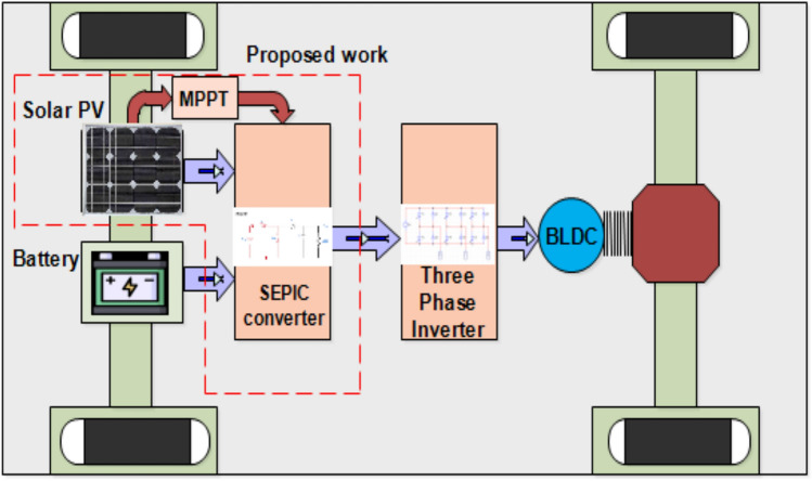
The architecture of hybrid EV is shown in Fig. 1. In which dotted box shows the proposed work in this research. The maximum power from solar PV is extracted through SFO-MPPT controlled modified high step-up SEPIC converter. Hence this work focuses on detailed analysis of proposed converter and switching pulse generation through SFO-MPPT control technique.
Fig. 1.
Architecture of Hybrid EV.
Novel contributions to the field of research
A modified high step-up converter is designed and its steady state performance is analyzed theoretically and verified the performance through simulation study and experimental work.
Sunflower Optimization algorithm has been used in MPPT controller to trace maximum power output form solar PV during variable solar irradiance condition and variable load condition.
The suitability of the proposed converter with SFO-MPPT controller for multisource electric vehicle application is also verified
The proposed converter is designed to handle a 100W, 24 V solar panel. The maximum voltage conversion ratio achieved by this converter is 7.92 and output voltage yielded is 190 V. The maximum conversion efficiency achieved by this converter is 95.63%. The proposed converter has reduced number of components and the current ripple, voltage ripple have been reduced in the proposed converter. The voltage stress across the switch has also been reduced. Hence this converter finds application in multi-source fed hybrid electric vehicle applications. This research work is detailed as follows: section “Introduction” elucidates the steady state operation of the proposed converter. Section “The modified SEPIC converter” deals with the voltage conversion ratio of the proposed converter. Section “Small signal modeling” describes the design consideration. The small signal modeling is detailed in section “Simulation results and discussion”. The control strategy and implementation are detailed in section “Experimental results and discussion”. Finally, the simulation results and hardware results are discussed and Sect. 7 concludes the work.
The modified SEPIC converter
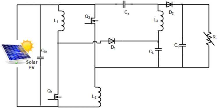
The proposed modified hybrid converter resembles both interleaved and SEPIC converter topology as shown in Fig. 2. It consists of two shunt legs having one active switch series connected with inductors. The third leg across the load consists of inductor-capacitor combination. The source and load are interconnected through two power diodes. There is output capacitor adopted in parallel with load resistance RL for filtering requirement. This topology aims to improve the voltage conversion ratio drastically. The mode of operation of the proposed converter is explained in the following section.
Fig. 2.
The high gain modified SEPIC converter.
Mode 1:
During this mode, both the switches are turned ON and thus two inductors L1, L2 get charged. The inductor L3 is getting energy from the arm capacitor Ca and filter capacitor CL as shown in Fig. 3. The output capacitor Co connected across the load supplies the load resistor RL. The steady-state equations of mode 1 operation are derived as follows:
 |
1 |
 |
2 |
 |
3 |
 |
4 |
Fig. 3.
Mode 1 operation of the proposed converter.
Mode 2:
During this mode, the active switches are in OFF condition which in turn makes the diode to be in ON condition. The charged inductors L1,L2 are supposed to discharge during this mode. Similarly, the energy stored in inductor L3 is also released through capacitor Ca and L1 which makes the closed loop as depicted in the Fig. 4. The input capacitor provides protection against solar panel. If inductor current is more than the source voltage, then input capacitor gets charged. The expected key waveforms of the proposed converter are depicted in Fig. 5.The steady state equations are deriving as follows:
Fig. 4.
Mode 2 operation of the proposed converter.
Fig. 5.

The key wave form high step up modified SEPIC converter.
Assuming the voltage across the inductor L1 and L2 are equal,
 |
5 |
 |
6 |
 |
7 |
Voltage conversion ratio
The proposed converter voltage conversion ratio is derived based on the steady-state equations of mode of operation. Apply voltage–time balance equation for the inductor L3
 |
8 |
 |
9 |
 |
10 |
 |
11 |
On solving the above equations, the voltage conversion ratio of the converter is obtained as,
 |
12 |
The voltage conversion ratio different converters are shown in Fig. 6. The proposed converter yield better voltage conversion ratio compared to all other converters.
Fig. 6.

The voltage conversion ratio of different converters.
Design consideration
The passive components present in the proposed converter are chosen based on the following equation derived from mode of operation. To operate the proposed converter in continuous conduction mode, the value of inductor chosen is very important.
 |
13 |
The value of output capacitor is chosen based on the ripple voltage across the capacitor,
 |
14 |
The arm capacitor Ca and leg capacitor CL values are chosen as follows,
 |
15 |
Small signal modeling
Since the state-space analysis is easier and it has lot of advantages than other methods, the state-space method is preferred for small signal modeling. The following equations are derived based on the steady-state equations of mode of operation.
 |
16 |
where C (s), R(s) represent the output and input of the proposed converter and the co-efficient A = A + (1 − D) A represent system matrix, B = B + (1 − D)B represent input matrix, C = C + (1 − D)C represent output matrix and d = D + (1 − D)d represent transmission matrix respectively. The generalized state model of any system is described as follows
 |
17 |
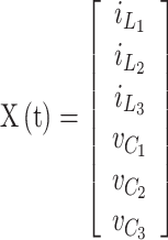
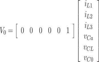
The choice of state variables is chosen randomly rather than unique and It is chosen as follows:
 |
18 |
 |
19 |
 |
20 |
 |
21 |
 |
22 |
Stability analysis
To analyze the stability of the proposed converter, the state equation and output equations are converted into transfer function using the Eq. (16). The derived transfer function is of order 6 as described in Eq. (23).
 |
23 |
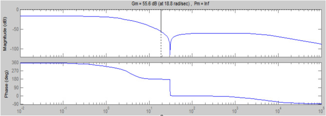
To give better transient performance, PI controller has been designed whose gain is tuned by Zeigler-Nichols method. The better performance is obtained when gain of the PI controller is set as follows: KI = 0.7831 and Kp = 0.01271. For step input, the transient performance of the system is measured; settling time = 0.19 s, peak overshoot = 0.12%, steady state error = 0.63%. To analyze the stability of the proposed converter, Bode plot is drawn for Eq. (23) using MATLAB/R2022a and it is noted that gain margin Pm = infinity and Phase margin Gm = 55.6 dB as shown in Fig. 7 which implies the designed converter is stable.
Fig. 7.
Bode plot for the proposed converter.
Sunflower optimization controller
SFO is the recently introduced optimization technique that came into engineering era in the year 2019 to solve the non-linear problem formulated which is inspired by natural practice. It imitates the orientation of sunflower towards the sun to get maximum solar radiation throughout the day. This is a meta-heuristics algorithm that offers global search optimization rather than local search. During the movement of sunflower, it may fertilize with closest neighboring sunflower to produce the next generation sunflower. There may be ‘n’ number of pollen that came from sunflower during fertilization in real sunflower but it is assumed that only one pollen is seeded into the neighboring sunflower that offers accurate and fast optimization. It also follows sunflower inverse square law.
 |
24 |
where I- represents intensity of solar radiation,  represents Sun power, r- represents distance between sun and sunflower. The sunflower move towards the sun based on following mathematical expression,
 |
25 |
where S*-represents best solution, Si- solution at ith iteration.
In each step, sunflower move towards the sun by following mathematical model expression,
 |
26 |
where  -represents the inertial displacement,
  - represents the probability of pollination.
To avoid the minimum and maximum limit control parameter, it is restricted as follows
 |
27 |
where Smax,Smin represents the maximum and minimum values of the solution and ‘n’ represents the population size.
On each step, the cost function is minimized to align towards the sun by updating the new position. It is mathematically expressed as follows
 |
28 |
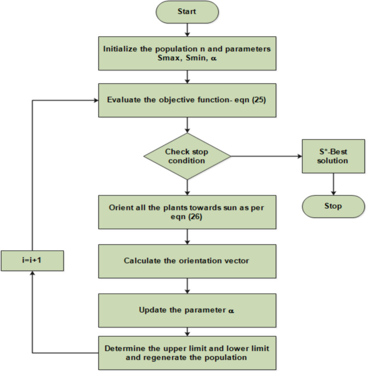
where Si+1 represent the new sunflower orientation, Si represents current position. The detailed process of SFO to generate switching pulses to the proposed converter has been depicted in Fig. 8.
Fig. 8.
Flowchart of SFO.
Simulation results and discussion
The proposed converter is constructed using the components listed in Table 1. To analyze the performance of proposed converter, it is simulated using MATLAB/R2022a simulink environment under different operating conditions like steady state, variable input voltage and variable load condition. The following section elucidates the simulation analysis of proposed converter (Fig. 8).
Table 1.
Performance comparison different MPPT controllers.
| MPPT methods | Rise time (sec) | Settling time (sec) | Peak overshoot (%) | Steady state error (%) |
|---|---|---|---|---|
| PSO | 0.032 | 0.23 | 1.7 | 0.17 |
| IC | 0.045 | 0.17 | 1.42 | 0.14 |
| Variable step size FLC | 0.023 | 0.14 | 1.3 | 0.123 |
| ANN | 0.011 | 0.12 | 1.01 | 0.11 |
| SFO | 0.005 | 0.067 | 0.67 | 0.07 |
-
(i)
The performance of proposed converter under Steady-state condition:
The proposed converter is energized using 100W, 24 V solar panel with short circuit current of 3.13 A. The maximum voltage corresponds to maximum power point is 35 V. The input voltage is stepped up into 190 V when the duty ratio is kept at 0.7 as shown in Fig. 9. The voltage across the capacitors Ca, CL remains half of the output voltage as shown in Fig. 10. The inductors IL1, IL2 are charging and discharging simultaneously during the steady state condition as shown in the Fig. 11.
-
(ii)
The performance of proposed converter under dynamic solar irradiance condition:
To analyze the performance of the proposed converter, the solar irradiance is varied as follows: 1000 W/m2 for (0 to 1 s), 500 W/m2 for (1–2 s) and 1500 W/m2 for (2 to 3 Seconds) as shown in Fig. 12. The corresponding input voltage variation is depicted in the Fig. 13. However, the load voltage remains 190 V as shown in Fig. 14 where there are two spikes in the output voltage waveform due to variation of solar irradiance in such a way that the controller gives dynamic pulses to the converter switches. Figures 15 and 16 shows Sunflower Optimization (SFO) based maximum power tracing under dynamic solar irradiance condition. Various MPPT algorithms have been taken into consideration to verify the effectiveness of the proposed MPPT method in terms of steady state and transient performance and it is well proven that the proposed method outperforms all the conventional converter used in the literature from Table 1. The reason for selecting SFO algorithm compared to PSO algorithms are as follows: it could effectively trace maximum power under variable irradiance condition and variable load condition. The steady state and transient performance have been improved compared to other conventional control algorithms.
-
(iii)
The performance of proposed converter under variable load condition:
The performance of the proposed converter is tested under variable load condition. The variation of load is as follows: 5A for (0 to 1 s), 2.5A for (1 to 2 s) and 3.5 A for (2 to 3 Seconds) as indicated in Fig. 17. The input voltage remains 24 V and the load voltage remains 190 V by dynamic adjustment of pulses generated by SFO controller as depicted in the Figs. 16 and 18. During the variation of the current load, initial spike is observed in Fig. 16 in which duration of pulse is very minimum which will not affect load severely at any cost.
Fig. 9.
The output voltage of the proposed converter.
Fig. 10.
The voltage across capacitors Ca, CL.
Fig. 11.
The input current IL1, IL2.
Fig. 12.
The variable solar irradiance.
Fig. 13.
The variation of source voltage with respect to solar irradiance.
Fig. 14.
The load voltage during variable solar irradiance.
Fig. 15.
Sun Flower Optimization (SFO) based maximum power tracing.
Fig. 16.
Solar PV output voltage.
Fig. 17.
Variation of load current.
Fig. 18.
The load voltage during variation of the load current.
Experimental results and discussion
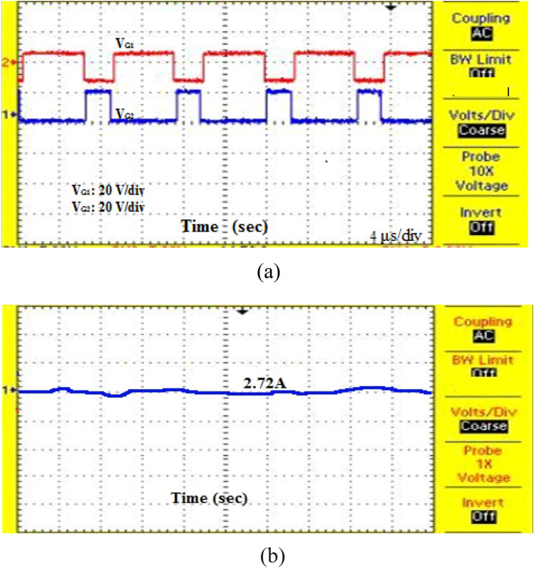
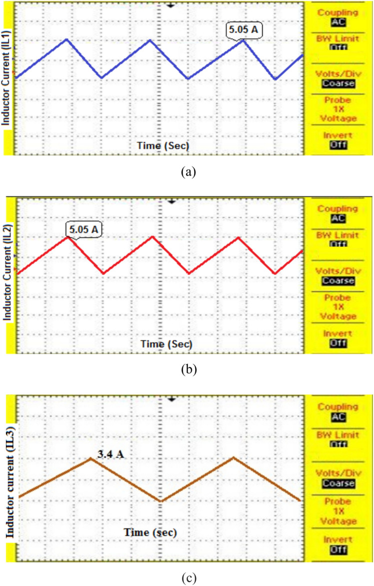
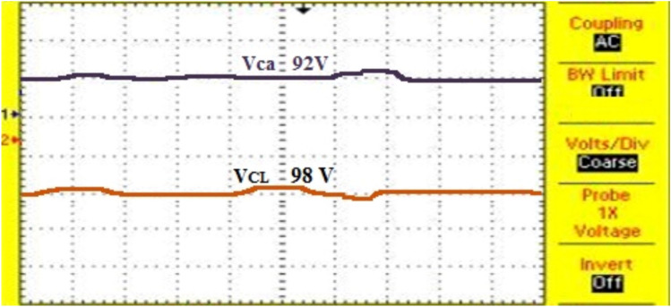
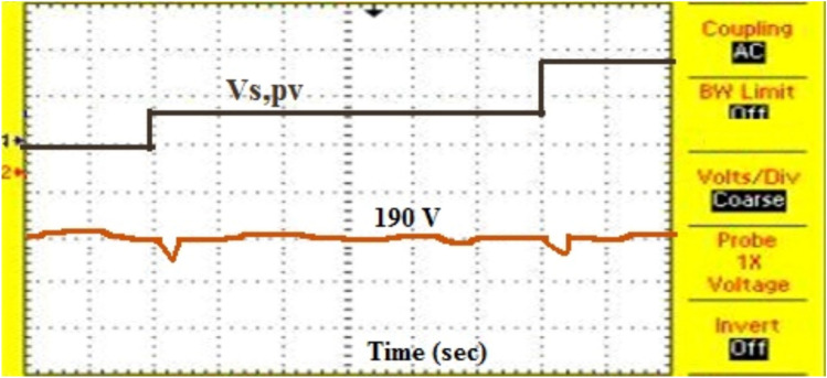
To validate the performance of the proposed converter, a real time experimental set up is constructed as depicted in the Fig. 19 using the components listed in Table 2. A 200 V, N-channel IRFD220PBF MOSFET with on time resistance RDS(on) of 0.8 Ω switches are used in experimental set-up. The diode used in this converter is MP20200CTG with maximum reverse voltage of 200 V and continuous forward current of 20A is used. The proposed converter is energized using a 100W solar PV which gives the constant voltage of 24 V under steady state condition. The solar panel is made from mono-crystalline material in which maximum voltage at maximum power point is 35 V. The solar panel rating can be expanded by connecting in series up to 6 panels. The switching pulses generated to switch S1, S2 and input current from are depicted in the Fig. 20. Both the switches are triggered and turned off simultaneously. The input voltage of 24 V is stepped up to 190 V as shown in Fig. 21. The inductor current IL1, IL2 and IL3are showed in shown in Fig. 22. The arm capacitor Ca and Leg capacitor CL voltage waveforms are shown in Fig. 23. The dynamic response of the proposed converter to change in light intensity and load current are depicted in the Figs. 24 and 25. The various converter parameters used in the proposed converter are compared against other converters used by the pioneers in the state of art. The proposed converter could yield better voltage regulation compared to other converters as given in Table 3. However, the number of L and C used in this converter are more compared to other converters. The maximum conversion efficiency achieved by this converter is 95.63% as shown in Fig. 26.
Fig. 19.

Experimental prototype of modified High-step up SEPIC converter.
Table 2.
Hardware components.
| SNo | Parameters | Specification |
|---|---|---|
| 1 | Inductors L1 = L2 = L3 | 300µH |
| 2 | Capacitors CL = Ca | 10µF |
| 3 | Output capacitor Co | 98µF |
| 4 | Switching frequency | 20 kHz |
| 5 | Resistive load | 1kΩ |
| 6 | Input Capacitor Cin | 100 µF |
Fig. 20.
(a) Switching pulses generated to switch S1, S2 (b) Input current waveform.
Fig. 21.
The output voltage of the proposed converter.
Fig. 22.
(a) inductor current IL1, (b) inductor current IL2 (c) inductor current IL3.
Fig. 23.
Capacitor voltage.
Fig. 24.
Dynamic response of the proposed converter to changes in light intensity.
Fig. 25.
Dynamic response of the proposed converter to changes in load current.
Table 3.
The comparison of different DC-DC converters.
| Circuit topology (reference no) | Circuit components | Voltage gain | Max.voltage across switch in V | ΔI (I/p current ripple in A) | ΔVc (Capacitor voltage ripple in V) | Max. efficiency in % | |||
|---|---|---|---|---|---|---|---|---|---|
| No of switches | No of Diodes | No of inductors | No of Capacitors | ||||||
| conventional SEPIC converter | 1 | 1 | 2 | 2 |  |
65 | 10 | 32 | 92 |
| converter (ref 16 ) | 1 | 2 | 2 | 3 |  |
83 | 5 | 8.25 | 92.2 |
| Converter (ref 21) | 1 | 3 | 3 | 3 |  |
24 | 19.6 | 12 | 94.8 |
| Converter (ref 22) | 1 | 4 | 3 | 4 |  |
255 | 9.29 | 2.3 | 94.2 |
| Converter (ref 23) | 1 | 4 | 2 | 4 |  |
60 | 7 | 20 | 95.1 |
| Proposed converter | 2 | 2 | 3 | 3 |  |
80 | 6 | 8 | 95.63 |
Fig. 26.

The conversion efficiency of proposed converter.
Loss analysis
The efficiency of the proposed converter can be expressed as
 |
29 |
Ploss is the total loss of the converter, which includes MOSFET switch loss, diode loss, inductor loss, capacitor loss and other miscellaneous losses as expressed in equation.
 |
30 |
MOSFET switch has two loss components. They are switching loss of switch and conduction of the switch as described in Eq. (23) and (24).
 |
31 |
 |
32 |
The diode loss can be calculated as given in Eq. (25)
 |
33 |
The capacitor and inductor losses can be calculated by multiplying square of current flowing through component with parasitic resistance of the component. The switching frequency is maintained at 20 kHz which contributes to 22 percent over loss as depicted in the loss break-down Fig. 27.
Fig. 27.
Loss break-down of the proposed converter.
Conclusion
A modified SEPIC converter topology was introduced in this research work. The proposed converter was energized by solar PV where the maximum power extraction ensured by implementing SFO control technique. A detailed steady state operation, small signal modeling and design consideration elaborated. The proposed converter along with SFO control technique simulated using MATLAB/R2015a environment under steady state and dynamic operating conditions. The theoretical and simulation results were validated by constructing a prototype in the laboratory. The experimental results showed the conversion efficiency of 95.63%. The performance of the proposed converter was compared against state of art and it was evident that the proposed converter was suitable for solar PV applications. In future, the impact of the proposed converter excited by solar PV and battery along with inverter fed PMBLDC motor will be analyzed which is actually adopted in hybrid EV.
Acknowledgements
All authors would like to express their gratitude to the United Arab Emirates University, Al Ain, UAE, for providing financial support with Grant No. 12R283. In addition, we would like to extend our appreciation to the Deanship of Research and Graduate Studies at King Khalid University for funding this work through Large Research Project under grant number RGP2/347/45.
Abbreviations
- SEPIC
Single Ended Primary Inductor Converter
- SFO
Sun Flower Optimization
- PEMFC
Proton Exchange Membrane Fuel Cell
- MPPT
Maximum Power Point Tracking
- BLDC
Brush Less DC
- PV
Photovoltaic
- EV
Electric Vehicle
- PFC
Power Factor Correction
- ANN
Artificial Neural Network
- PWM
Pulse Width Modulation
List of symbols
- Q1, Q2
Switches used in the converter
- D1, D2
Diodes used in the converter
- L1, L2, L3
Inductors used in the converter
- Ca, CL, Co
Capacitors used in the converter
- iL1, iL2, iL3
Current through inductors L1,L2,L3
- VCa, VCL, VCO
Voltage across the capacitors Ca, CL, Co
- D
Duty cycle
- Vspv
Source voltage
- fs
Switching frequency
- ∆iL
Inductor ripple current
- ∆Vc
Capacitor ripple voltage

Output power

Total loss of the converter

Switching loss of MOSFET

Conduction loss of MOSFET

Diode loss

Capacitor loss

Inductor loss

Miscellaneous loss
- trise, tfall
Rise time and fall time of MOSFET
- VDS,iDS
Drain to source voltage, drain current
- VFD, IFD
Forward diode voltage, diode current
- rDS(on), rD
On-time MOSFET resistance, Diode resistance
Author contributions
K.B.: Validation, Visualization, Writing – review & editing. S.V.: Writing – original draft, Validation, Methodology, Investigation, Formal analysis, Conceptualization. P.R.: Writing – original draft, Methodology, Investigation, Formal analysis, Conceptualization. M.M.A.: Formal analysis, Methodology, Software, Validation. Q.M.Al-M.: Visualization, Validation, Funding.
Data availability
The datasets used and/or analysed during the current study available from the corresponding author on reasonable request.
Declarations
Competing interests
The authors declare no competing interests.
Footnotes
Publisher’s note
Springer Nature remains neutral with regard to jurisdictional claims in published maps and institutional affiliations.
References
- 1.Ravindran, V., Ponraj, R., Zameerbasha, S.S., Kanna, N.S., SamuelRaj, S. and Sabarish, B., Dynamic performance enhancement of modified sepic converter. In 2021 2nd International Conference for Emerging Technology (INCET) (pp. 1–5). IEEE (2021).
- 2.Chandran, P., Sangeetha, N., Shalini, M. and Srijanani, O., 2021, October. Design and simulation analysis of modified single switch SEPIC converter for BLDC motor. In 2021 IEEE Mysore Sub Section International Conference (MysuruCon) (pp. 530–537). IEEE.
- 3.Natchimuthu, S., Chinnusamy, M. & Mark, A. P. Experimental investigation of PV based modified SEPIC converter fed hybrid electric vehicle (PV-HEV). Int. J. Circuit Theory Appl.48(6), 980–996 (2020). [Google Scholar]
- 4.Anuradha, C., Chellammal, N., Saquib Maqsood, M. & Vijayalakshmi, S. Design and analysis of non-isolated three-port SEPIC converter for integrating renewable energy sources. Energies12(2), 221 (2019). [Google Scholar]
- 5.Asy’Ari, M.K., Toriki, M.B. and Apriajumita, B.E., Design of fuzzy logic control based on SEPIC converter for MPPT on wind turbine. In 2022 International Seminar on Intelligent Technology and Its Applications (ISITIA) (pp. 444–448). IEEE (2022).
- 6.Rais, Y., El Aroudi, A., Zakriti, A. & Khamlichi, A. Modeling and design of voltage-mode controlled PV-fed SEPIC converter. IFAC-Papers Online55(12), 514–519 (2022). [Google Scholar]
- 7.Kannan, R. & Sundharajan, V. A novel MPPT controller based PEMFC system for electric vehicle applications with interleaved SEPIC converter. Int. J. Hydrogen Energy48(38), 14391–14405 (2023). [Google Scholar]
- 8.Vijayalakshmi, S., Marimuthu, M., Jayakumar, N., Vighneshwari, B.D., Paranthagan, B., Rani, N.C. and Shenbagalakshmi, R., 2022. A novel double frequency SEPIC converter with improved transient characteristics and efficiency. J. Electr. Eng. Technol., 1–12.
- 9.Rosas-Caro, J. C. et al. A novel DC-DC multilevel SEPIC converter for PEMFC systems. Int. J. Hydrogen Energy41(48), 23401–23408 (2016). [Google Scholar]
- 10.Renethaa Desline, D. R. & Vijayarajan, S. DFO and PI based dual control for single stage SEPIC and LLC based PFC converter. J. Electr. Eng. Technol.17(4), 2285–2298 (2022). [Google Scholar]
- 11.Saravanan, S. & Usha Rani, P. A novel high gain interleaved luo Dc–Dc converter with cascaded fuzzy logic controller for PV system application. J. Electr. Eng. Technol.18(2), 925–940 (2022). [Google Scholar]
- 12.Lee, S. W. & Do, H. L. High step-up-coupled inductor SEPIC DC–DC converter with input current ripple cancellation. J. Power Electron.22(5), 739–749 (2022). [Google Scholar]
- 13.Bouafassa, A., Fernández-Ramírez, L. M. & Babes, B. Power quality improvements of arc welding power supplies by modified bridgeless SEPIC PFC converter. J. Power Electron.20(6), 1445–1455 (2020). [Google Scholar]
- 14.Kumari, N., Kumar, S. S. & Laxmi, V. Self-balanced single-inductor single-input multiple-output bipolar DC–DC converter based on SEPIC-Ćuk combination with no cross-regulation. Electr. Eng.105(2), 1267–1285 (2023). [Google Scholar]
- 15.Al-Gahtani, S. F., Azazi, H. Z. & Elbarbary, Z. S. Three-phase SEPIC PFC for three-phase IM drive under unbalanced and distorted voltage supply. Electr. Eng.103, 357–371 (2021). [Google Scholar]
- 16.Karthikeyan, B., Sundararaju, K. & Palanisamy, R. ANN-based MPPT controller for PEM fuel cell energized interleaved resonant PWM high step Up DC-DC converter with SVPWM inverter fed induction motor drive. Iran. J. Sci. Technol. Trans. Electr. Eng.45, 861–877 (2021). [Google Scholar]
- 17.Jyothi, B., Bhavana, P., Rao, B. T., Pushkarna, M. & Djidimbele, R. Implementation of modified SEPIC converter for renewable energy built DC microgrids. Int. J. Photoenergy2023(1), 2620367 (2023). [Google Scholar]
- 18.Selvam, S., Sannasy, M. & Sridharan, M. Analysis of improved gain switched inductor super lift cell-based modified SEPIC converter for DC microgrid. Electr. Eng.105(4), 2199–2215 (2023). [Google Scholar]
- 19.Shunmathi, M. & Gnanavadivel, J. Modified bridgeless PFC-based Cuk-Sepic converter with improved power quality for arc welding applications. IETE J. Res.70(3), 3234–3244 (2023). [Google Scholar]
- 20.Paul, E., Sannasy, M. and Naik, S.V., 2023, March. Design of high gain modified SEPIC Converter for grid connected PV systems with MPPT control. In 2023 IEEE IAS Global Conference on Renewable Energy and Hydrogen Technologies (GlobConHT) (pp. 1–5). IEEE.
- 21.Gules, R., Dos Santos, W. M., Dos Reis, F. A., Romaneli, E. F. R. & Badin, A. A. A modified SEPIC converter with high static gain for renewable applications. IEEE Trans. Power Electron.29(11), 5860–5871 (2013). [Google Scholar]
- 22.Jyothi, B., Bhavana, P., Rao, B. T., Pushkarna, M. & Kitmo, D. R. Implementation of modified SEPIC converter for renewable energy built DC microgrids. Int. J. Photoenergy2023, 1–13 (2023). [Google Scholar]
- 23.Maroti, P. K., Esmaeili, S., Iqbal, A. & Meraj, M. High step-up single switch quadratic modified SEPIC converter for DC microgrid applications. IET Power Electron.13(16), 3717–3726 (2020). [Google Scholar]
Associated Data
This section collects any data citations, data availability statements, or supplementary materials included in this article.
Data Availability Statement
The datasets used and/or analysed during the current study available from the corresponding author on reasonable request.


