

Summary
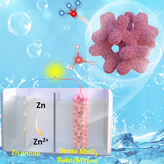
Ambient temperature electrochemical ammonia synthesis via nitrate reduction reaction (NO3RR) is a promising alternative to the energy-intensive Haber-Bosch process but lacks effective electrocatalysts for practical applications. In this work, MnO2 2D-nanoflakes are anchored onto 2D-MXene Ti3C2Tx, forming a heterogeneous catalyst for NO3RR with an ammonia yield of 14.06 ± 0.48 mg h−1.mgcat−1 at −1.2 V versus reversible hydrogen electrode (vs. RHE) and a Faradaic efficiency (FE) of 85.23 ± 1.62% at −1.0 vs. RHE, along with good stability over six consecutive cycles, with NH3 FE exceeding 75% at −1.0 V vs. RHE in 0.5 M K2SO4 and 0.1 M KNO3 electrolyte. As a cathode in a Zn-NO3− battery with a polished Zn plate from spent Zn-C batteries as anode, it delivers a power density of 0.323 mW cm−2 and NH3 FE of ∼79.9%. This study highlights a highly effective electrocatalyst for NO3RR and its potential in self-powered NH3 production.
Subject areas: Chemistry, Energy engineering, Materials science
Graphical abstract
Highlights
-
•
2D/2D MnO2/MXene hybrids are used for electrochemical nitrate-to-ammonia conversion
-
•
The optimized MnO2/MXene exhibits NH3 Faradaic efficiency over 85%
-
•
The optimized MnO2/MXene shows promising Zn-NO3− battery behavior
Chemistry; Energy engineering; Materials science
Introduction
Ammonia (NH3) is an indispensable precursor for nitrogen-related industrial products and serves as a promising hydrogen carrier (17.6 wt % of hydrogen).1,2 At present, the practical-scale NH3 production depends predominantly on the conventional energy-intensive Haber-Bosch process, which operates under extreme conditions (300°C–500°C, >200 atm).3,4 Despite its efficiency for a century, its substantial environmental impact remains a significant concern, as it constitutes ∼1%–2% of the total global energy consumption per annum and contributes ∼1.3% of energy-related CO2 emissions.5 Achieving carbon neutrality necessitates the urgent development of sustainable and efficient technologies for synthesizing ammonia and nitrogen-based products that can partially or entirely replace the Haber-Bosch process.6,7
The nitrate-to-ammonia electrochemical reduction (NO3RR) has emerged as an appealing replacement to the century-old Haber-Bosch process because of its ability to utilize renewable energy sources and operate under mild reaction conditions.8,9,10 In comparison to the nitrogen-to-ammonia reduction reaction (NRR), NO3RR exhibits greater thermodynamic favorability owing to the substantially lower bond dissociation energy of the N=O bond (204 kJ mol−1) in contrast to the considerably higher dissociation energy of the N≡N bond (941 kJ mol−1).11 Additionally, the substantial potential gap between NO3RR and the competitive hydrogen evolution reaction (HER) (0.69 V) is markedly larger than that between NRR and HER (0.09 V), indicating that NO3RR is less susceptible to HER interference.12 However, NO3RR proceeds through complex multi-step reaction pathways, requiring the transfer of eight electrons and nine protons in aqueous media, which results in sluggish reaction kinetics and the generation of multiple byproducts.13 Moreover, parasitic HER may still occur at highly negative potentials, competing with NO3RR and limiting NH3 production efficiency, thereby hindering its practical application.14,15,16 Consequently, developing highly efficient and cost-effective electrocatalysts for NO3RR to NH3 remains an urgent yet formidable challenge.
Possessing well-defined structures and tunable electronic properties, two-dimensional (2D) materials with massive active sites and a high surface area are suitable candidates for electrocatalysts.17,18 Currently, titanium carbide MXene (Ti3C2Tx) etched from MAX phase (Ti3AlC2) exhibits outstanding electrical conductivity, hydrophilicity, and an easily modifiable surface area, which can be attributed to its distinctive structural characteristics.19,20 Besides that, owing to the dense functional groups, Ti3C2Tx MXene serves as an effective platform for anchoring and dispersing various electrocatalysts.21,22 The functional surface groups (e.g., -F, -O, and -OH), formed via the etching and delamination process, enhance the dispersibility of Ti3C2Tx MXene in aqueous solutions and facilitate its integration with other 2D materials via solution-based assembly techniques.23 Meanwhile, manganese dioxide (MnO2) has attracted considerable interest for its remarkable electrochemical properties, which can be tailored through synthetic modifications to optimize its redox behavior.24,25,26 However, MnO2 exhibits limited electrical conductivity, which can be significantly improved through hybridization with MXene.27,28
Inspired by the above discussion, we have developed heterogeneous 2D/2D MnO2/MXene hybrids, wherein MnO2 nanoflakes are grown on MXene nanosheets to facilitate NO3RR performance. This hybrid structure is expected to provide an increased number of active sites and mass transport channels, thereby improving NO3RR performance. The proportion of MXene to MnO2 can be precisely regulated by modifying the concentration of KMnO4 precursor, with the most catalytically active configuration exhibiting a dense flower-like morphology at the nanoscale. The variations in compositional, structural, and electrochemical properties of the synthesized catalysts were thoroughly examined utilizing advanced spectroscopic and electrochemical techniques. The as-prepared dense MnO2/MXene hybrid exhibited an NH3 yield rate of 14.06 ± 0.48 mg h−1.mgcat−1 at −1.2 V vs. RHE and a maximum NH3 FE of 85.23 ± 1.62% at −1.0 V vs. RHE. Furthermore, the catalyst maintained NH3 FE above 75% over six consecutive cycles with a long-term operational stability of 6 h. Finally, a fabricated zinc-nitrate (Zn-NO3−) battery system, utilizing a polished Zn plate recovered from spent Zn-carbon batteries, demonstrated the potential for multifunctional applications, including material recycling, high-power-density electricity generation, and ammonia production.
Results and discussion
Materials synthesis
As shown in Figure 1A, a schematic diagram illustrates the synthesis process of MnO2/MXene catalysts through a three-step process (detailed in the Experimental Section). In the first step, multi-layer MXene was thermally etched by concentrated HF at 50°C from MAX phase according to a method reported elsewhere with some modifications.19 Subsequently, the collected multi-layer MXene was dissolved in DMSO for intercalation, followed by sonication treatment for peeling it off into few-layer flakes with small particle size, which increases the available surface area. In the final stage, the precipitated few-layer MXene was dispersed in ethanol to generate a homogeneous solution. Then, by slowly adding KMnO4 precursor to the above solution, MnO2 nanoflakes were vertically grown on the MXene surface while preserving MXene morphology.
Figure 1.

Materials synthesis and characterization
(A) Schematic illustration of the preparation of as-prepared MnO2/MXene catalysts. Characterization of as-prepared catalysts: (B) XRD patterns, (C) Raman, (D) BET surface area measured from nitrogen adsorption-desorption isotherms and, (E) the corresponding pore-size distribution.
Phase composition and crystallographic analysis
The phase composition and crystallographic properties of MnO2/MXene, along with single-component MnO2 and MXene, were initially examined through X-ray diffraction (XRD) analysis. As depicted in Figure 1B, there are several characteristic diffraction peaks observed in the MXene component, where the diffraction peaks at 2θ = 8.61°, 18.25°, 22.27°, 28.04°, and 60.63° are related to the (002), (004), (006), (008), and (110) planes of MXene Ti3C2Tx, respectively, which aligns with findings reported in previous literature.27 In the XRD pattern of pure MnO2, the peaks located at 15.60°, 22.16°, and 41.52° represent the (001), (002), and (200) planes, respectively, which are assigned to δ-MnO2 (JCPDS80-1098).29 Following the addition of the KMnO4 solution, the MnO2/MXene hybrids displayed well-defined diffraction peaks attributable to both MnO2 and MXene, validating the effective incorporation of these two phases within the composite structure.
Vibrational characteristics and interfacial interaction revealed by Raman spectroscopy
The Raman spectra of the synthesized catalysts, obtained under excitation with a 532 nm green laser, are presented in Figure 1C. The Raman spectrum of MXene exhibited a distinctive peak at 150 cm−1, attributed to the in-plane vibrational mode (A1g) of the Ti-C bond, aligning with previously reported findings.30 One major peak was observed in the MnO2 Raman spectrum related to the symmetrical stretching vibrations (Eg) around 600–650 cm−1 of Mn-O, which are associated with the MnO6 octahedral.31 The Raman spectra of the MnO2/MXene hybrids showed the characteristic peaks of both MnO2 and MXene.32 From the sparse MnO2/MXene to MnO2 urchin/MXene with the increase in MnO2 loading, the intensities of Mn-O symmetric stretching vibration increased and shifted slightly toward a higher frequency, which can be associated with the increased force constant of stretching vibrations of Mn–O bonds.33 Due to the interaction of MXene component, electrons tend to transfer from Mn3+ sites in MnO2 to Ti4+ sites in MXene, further strengthening the Mn–O bonds, which can be explained further by X-ray photoelectron spectroscopy (XPS) spectra in the following section.
Mesoporous structure formation in MnO2/MXene hybrids
The characterization of pore architecture was conducted via Brunauer-Emmett-Teller (BET) testing, which exhibited a type IV profile accompanied by H3 hysteresis loops, indicating the presence of a mesoporous framework predominantly consisting of lamellar, slit-like voids (Figures 1D and S1, supplemental information).34,35 Growing MnO2 nanoflakes presents a distinctive approach to augmenting the effective surface area while mitigating the undesirable restacking of MXene layers, leading to the enhanced surface area of MnO2/MXene hybrids compared to single component MXene, as shown in Table S1 (supplemental information). Besides that, except MXene, the MnO2 and MnO2/MXene hybrids present the pore size in 2–20 nm, confirming the mesoporous structures (Figures 1E and S2, supplemental information), where V and D denoted as pore volume and pore diameter, respectively. This demonstrates that incorporating MnO2 into MXene nanosheets can form the porous structure, favoring the mass/ions transport.
Morphological and crystallographic characterization of MnO2/MXene hybrids
As depicted in Figure S3 (supplemental information), the field emission scanning electron microscopy (FE-SEM) mapping of MnO2 revealed a sea urchin-like structure with burrs and uniform particle size, with diameter around 100–150 nm, while MXene specimen exhibited a stack of smooth nanolayers. After functionalization of MXene with precursor KMnO4 solution with different concentrations in 0.001 mol L−1 and 0.005 mol L−1, the formed MnO2 nanoflakes are uniformly decorated on the MXene surface, resulting in the fabrication of sparse MnO2/MXene and dense MnO2/MXene heterostructures which possess the massive mass transport channel and expose active sites (Figures 2A and 2B). Apparently, once increasing the precursor KMnO4 solution to 0.01 mol L−1, the component appears both MnO2 nanoflakes and massive urchin-like particles, which may lead to congestive mass transport channels and hinder the mass transportation due to the inherent low conductivity of extensive MnO2 amount (Figure 2C). As illustrated in Figure 2D, the distinct few-layered structure of MXene is clearly observed via high-resolution transmission electron microscopy (HR-TEM) image, confirming the successful fabrication of few-layer MXene. Besides that, MnO2 parts are distributed on the MXene skeleton which are identified through lattice fringes 0.35 nm of MnO2 (002) planes (Figures 2E and 2F).36,37
Figure 2.

Morphological and crystallographic characterization
FE-SEM micrographs of as-prepared catalysts: (A) sparse MnO2/MXene (scale bar, 250 nm), (B) dense MnO2/MXene (scale bar, 250 nm), and (C) MnO2 urchin/MXene (scale bar, 250 nm).
(D–F) HRTEM images (scale bar = 10 nm), (E and F) corresponding lattice space (scale bar, 2 nm), (G) The SAED pattern (scale bar, 5 nm−1), and (H) EDS mapping (scale bar , 1 μm) of dense MnO2/MXene.
To analyze the crystallographic characteristics of the dense MnO2/MXene composites, selected area electron diffraction (SAED) was employed. As depicted in Figure 2G, three distinct concentric diffraction rings are discernible, each corresponding to specific lattice planes of different crystalline phases. Notably, the innermost ring is associated with the (002) plane of MnO2, which formed during the MnO2 growth process. Meanwhile, the yellow rings, exhibiting progressively larger diameters, correspond to the (102) plane of MXene, whereas the last ring with the largest diameter represents the (110) plane of MXene.38 These results confirm the successful formation of the dense MnO2/MXene hybrid structure, wherein MnO2 nanoflakes are uniformly anchored onto the MXene framework, and both MnO2 and MXene maintain their crystalline nature. Furthermore, the surface element distribution of the dense MnO2/MXene was depicted in Figure 2H, where Mn, O, Al, Ti elements were detected and distributed on the catalyst surface.
Surface elemental composition and electronic coupling in MnO2/MXene hybrids
The surface component information of all as-prepared catalysts was revealed by XPS. In the full-scale XPS survey (Figure S4, supplemental information), an apparent Ti 2p signal is observed for the MXene and MXene/MnO2 hybrids. For comparison, the peaks assigned to C–Ti (281.26 eV), C-C (284.26 eV), C-O (287.26 eV), and C=O (288.86 eV) are present in the high-resolution C 1s XPS spectrum of MXene catalyst (Figure 3A), while the C 1s XPS spectrum of MnO2 shows with the concomitant disappearance of the C–Ti peak and three peaks at C-C (284.52 eV), C-O (286.12 eV), and C=O (288.52 eV).39 Four distinct peaks, representing the four distinct oxygen-containing functional groups, can be distinguished in the O 1s spectrum of MXene which are Ti-O bond at 528.16 eV, C-Ti-Ox bond at 529.36 eV, Ti-O-Ti bond at 531.56 eV, and C-Ti-(OH)x bond at 534.16 eV (Figure 3B).40 Besides that, the O 1s spectrum of MnO2 sample includes two distinct peaks at 529.52 eV and 531.92 eV, which are indicated to Mn-O-Mn and Mn-O-H, respectively. In MnO2/MXene hybrids, the fluctuation in density of deconvoluted O 1s peaks demonstrates the electronic interaction between MnO2 and MXene.
Figure 3.

Evaluation surface elemental composition
X-ray photoelectron spectroscopy spectra of all as-prepared catalysts: (A) C 1s, (B) O 1s, (C) Ti 2p, and (D) Mn 2p.
As shown in Figure 3C, in the Ti 2p spectrum of MXene, four major peaks were detected at 454.66, 456.06, 458.26, and 460.66 eV, which can be indicated to Ti-C 2p3/2, Ti2+ 2p3/2, Ti3+ 2p3/2, and Ti4+ 2p3/2, respectively.21 After compositing with MnO2, the difference in the positions of Ti 2p3/2, between MXene and MnO2/MXene hybrids is due to the decrease in Ti4+ intensity and the redshift in energy binding of Ti4+, which may be attributed to an electron transfer from MnO2 to MXene during the composite process. Besides that, the electronic structure of the magnesium in the MnO2 and MXene/MnO2 composites was further examined (Figure 3D).
In the MnO2 sample, the Mn 2p XPS spectrum exhibited a broad peak spanning from 638 to 651 eV, corresponding to the spin-orbit state of Mn 2p3/2. Deconvolution of this peak revealed two distinct components which are the Mn(IV) species at approximately 644.92 eV and the Mn(III) species at around 642.12 eV, indicating the coexistence of Mn(IV) and Mn(III) within the MnO2 structure. Upon integration of MnO2 with the MXene framework, the binding energy of Mn3+ 2p3/2 underwent a positive shift, implying the electron transfer from Mn3+ sites in MnO2 to Ti4+ sites in MXene, further strengthening the Mn–O bonds, which is consistent with Raman data. The modifications in the electronic structure of MnO2/MXene hybrids suggest a strong electronic interaction between MnO2 and MXene, which facilitates enhanced charge transfer between Ti3C2Tx and MnO2. This interaction is expected to improve the electrochemical performance of the material by promoting more efficient electron transport within the composite system.32,41
Nitrate-to-ammonia electrochemical reduction performance
The synergistic effect between the MnO2 and MXene components was systematically investigated by comparing the electrochemical nitrate reduction reaction (NO3RR) performance of the heterogeneous 2D/2D MnO2/MXene hybrids with those of the single-component MnO2 and MXene catalysts. The NO3RR activity was evaluated using a standard 3-electrode configuration H-type electrolysis cell (Figure S5, supplemental information) and preliminary catalytic activity was assessed through linear sweep voltammetry (LSV) in 0.5 M K2SO4 and 0.1 M KNO3. As depicted in Figures 4A and S6a (supplemental information), all as-prepared catalysts exhibited a markedly higher current density in the NO3−-containing electrolyte compared to bare K2SO4 solution, indicating that the enhanced current density primarily originates from the electrocatalytic reduction of NO3− ions. The dense MnO2/MXene hybrid demonstrated superior current density from the onset potential, achieving 91.6 mA cm−2 at −1.0 V vs. RHE, significantly outperforming single-component MnO2 and MXene catalysts. Moreover, the MnO2/MXene hybrids exhibited enhanced electron transfer kinetics, as evidenced by their lower Tafel slopes: 0.353 mV.dec−1 for dense MnO2/MXene, 0.373 mV.dec−1 for sparse MnO2/MXene, and 0.402 mV.dec−1 for MnO2 urchin/MXene—compared to MXene (0.434 mV.dec−1) and MnO2 (0.878 mV.dec−1) (Figures 4B and S6b, supplemental information). These results suggest that the dense MnO2/MXene hybrid exhibits the lowest energy barrier for NO3− adsorption and subsequent conversion.27
Figure 4.

Electrochemical evaluation of as-prepared catalysts for NO3RR
(A) Linear sweep voltammetry (LSV) at 5.0 mV s−1 in 0.5 M K2SO4 with and without 0.1 M KNO3, In 0.5 M K2SO4 and 0.1 M KNO3 electrolyte: (B) corresponding Tafel plot of nitrate reduction kinetics; (C) Electrochemical impedance spectroscopy (EIS) with 5 mV alternating current amplitude at an applied potential of −0.6 V vs. RHE; (D) Double-layer capacitance (Cdl) measurement for determining electrochemically active surface area; (E) Faradaic efficiency (FE) and (F) yield rate of NH3 as a function of overpotential for different catalysts. Error bars represent the standard deviation in yield rate and FE calculated after three tests for repeatability.
To gain deeper insights into the charge resistance characteristics of the synthesized catalysts, electrochemical impedance spectroscopy (EIS) was performed, and the associated Nyquist plots were analyzed (Figure S7a, supplemental information) reveal that MnO2/MXene hybrids exhibit smaller semicircle diameters than single-component MnO2 and MXene catalysts, indicative of enhanced charge transfer due to the interfacial synergy of the single-component 2D MnO2 and 2D MXene. Equivalent circuit modeling (Figure 4C) demonstrates that for MnO2/MXene hybrids, an uncompensated solution resistance (RS) is connected in series to two parallel constant phase elements (CPE1 and CPE2) and resistors (R1 and RCT).19 Conversely, for single-component MnO2 and MXene catalysts, RS is connected to a single parallel combination of a singular parallel network comprising a constant phase element (CPE) and a charge transfer resistance (RCT) (Figure S7b, supplemental information).42 The charge transfer resistance (RCT) at low frequencies, representing electron transfer across the electrode-electrolyte interface, was significantly lower for dense MnO2/MXene (5.001 Ω), confirming its superior charge transfer capability and efficient electron transport kinetics during NO3RR. Additionally, the presence of R1 in MnO2/MXene hybrids at high frequency is associated with interfacial resistance between MnO2 and MXene.43 Notably, the dense MnO2/MXene catalyst, characterized by abundant MnO2 nanoflakes, facilitates extensive electron/ion transport channels, thereby minimizing R1 (0.353 Ω) (Table S2, supplemental information). In contrast, the sparse MnO2/MXene and MnO2 urchin/MXene hybrids exhibit either insufficient or congested mass/ions transport pathways, leading to sluggish NO3RR kinetics. As a result, these findings demonstrate that the dense MnO2/MXene catalyst with optimal vertical-grown MnO2 nanoflakes can greatly facilitate fast electron/ion transfer, leading to promoted NO3RR activity.
The superior catalytic performance of the dense MnO2/MXene hybrid can be attributed to its increased electrochemically active surface area (ECSA), which facilitates extensive exposure of active sites. This was confirmed by determining the double-layer capacitance (Cdl) serving as a quantitative proxy for ECSA, calculated from cyclic voltammetry (CV) measurements recorded at various scan rates (Figure S8, supplemental information).44 As illustrated in Figures 4D and S9 (supplemental information), MnO2/MXene hybrids exhibit significantly higher Cdl values: 4.49 mF cm−2 for dense MnO2/MXene, 3.58 mF cm−2 for sparse MnO2/MXene, and 2.74 mF cm−2 for MnO2 urchin/MXene, compared to single-component MXene (2.74 mF cm−2) and MnO2 (0.581 mF cm−2), demonstrating the dense MnO2/MXene catalyst possesses the largest ECSA. The partial current density, which is proportional to NH3 yield rate, clearly demonstrates the enhanced activity and selectivity of the MnO2/MXene hybrids compared to single-component MnO2 and MXene catalysts (Figure S10, supplemental information). In particular, the dense MnO2/MXene exhibited the highest NH3 partial current density, with values 15.14- and 3.18-fold higher than those of MnO2 and MXene, respectively, at −1.0 V vs. RHE. Therefore, the improved NO3RR activity of MnO2/MXene hybrids suggests the presence of a synergistic effect between single component 2D MnO2 and 2D MXene catalysts.
Ammonia production efficiency
To further assess catalytic efficiency, electrolysis experiments were conducted at controlled potentials ranging from −0.7 to −1.2 V vs. RHE for 1 h in 0.5 M K2SO4 and 0.1 M KNO3 electrolyte, using all as-prepared catalysts as cathodes. Following chronoamperometry, the electrolyte was analyzed via ultraviolet-visible spectrophotometry to quantify NH3 and NO2− concentrations based on calibration curves (Figure S11, supplemental information). As shown in Figures 4E and S12a (supplemental information), NH3 yield rates progressively increased with more negative applied potentials, while FE of NH3 exhibited a volcano-shaped trend (Figures 4F and S12b, supplemental information), slightly decreasing at more negative potentials due to the competition of parasitic HER.45
Remarkably, the dense MnO2/MXene catalyst exhibited exceptional NO3RR activity, attaining the highest NH3 production rate of 14.06 ± 0.48 mg h−1.mgcat−1 at −1.2 V vs. RHE, along with a maximum NH3 FE of 85.23 ± 1.62% at −1.0 V vs. RHE. In conclusion, the superior NO3RR performance of the dense MnO2/MXene catalyst can be attributed to two key factors: (1) the synergistic interaction between 2D MnO2 and 2D MXene, which enhances charge transfer and boosts intrinsic electrocatalytic activity, and (2) the dense MnO2/MXene catalyst with the optimized MnO2 nanoflake density, which maximizes active sites and facilitates improved NO3RR kinetics.
Time-dependent nitrate reduction and ammonia formation kinetics
The relationship between the reaction time of the dense MnO2/MXene catalyst and the fluctuation of NO3−, NO2−, and NH3 concentrations during the reduction process was recorded at −1.0 V vs. RHE over 8 h in 0.5 M K2SO4 and 0.1 M KNO3 (6200 ppm NO3−) (Figure 5A). The NO3− concentration gradually decreases, while the NH3 concentration increases, demonstrating the linear conversion of nitrate to ammonia and indicating that the nitrogen in NH3 comes from NO3−. Meanwhile, the low concentration of produced NO2− ions implies high NH3 selectivity in the initial process and then gradually declines with reaction time, because of the subsequent reduction of the generated NO2− intermediate into several N-intermediates.46,47 However, due to significant NO3− consumption, the corresponding yield rate and FE of NH3 notably decrease after 8 h (Figure 5B). Furthermore, the negligible yield rate and FE of NO2− follow a trend similar to NH3, indicating that the change in NO3− concentration affects NO2− production during NO3RR (Figure S13). In addition, the time-concentration relationship of consumed NO3− was examined using a pseudo-first-order kinetic model (Figure 5C). The NO3− consumption rate increases rapidly in the first hour and then gradually slows until reaching equilibrium. The pseudo-first-order kinetic model estimates a maximum NO3− consumption of around 3979.43 ppm and a rate constant of 0.291 h−1.48
Figure 5.

NO3RR performance evaluation of dense MnO2/MXene
In 0.5 M K2SO4 and 0.1 M KNO3 at −1.0 V vs. RHE: (A) concentration-time curves of the NO3−, NO2−, and NH3 in NO3RR for 8 h; and (B) the corresponding and yield rate and FE of NH3 in NO3RR for 8 h; (C) the logarithmic relationship between time and consumed NO3− concentration during NO3RR for 8 h. FE and yield rate of NH3 in (D) 0.5 M K2SO4 and 0.1 M KNO3 solution with different pH; and in (E) 0.5 M K2SO4 solution with different concentrations of NO3−; (F) cyclic stability test with refreshing the electrolyte on FE and yield rate of NH3 in 0.5 M K2SO4 and 0.1 M KNO3, (1 cycle/1 h); and (G) performance comparison of different reported Mn-based and MXene-based catalysts for NO3RR to NH3 production in neutral electrolyte (See detailed information in Table S3, supplemental information).
Effect of electrolyte pH and nitrate concentration on NO3RR performance
To investigate the competition between NO3RR and the hydrogen evolution reaction (HER), NO3RR was conducted at 0.5 M K2SO4 and KNO3 0.1 M under different pH conditions. In acidic electrolytes, HER dominates due to its favorable kinetics, leading to low values of NH3 yield rate and FE (Figure 5D). In contrast, NO3−-to-NH3 performance increases and reaches a maximum NH3 FE of 88.2% ± 3.21% at pH 10, indicating that NO3RR is more favorable in neutral and alkaline electrolytes. This result suggests that OH− concentration enhances Hads (adsorbed hydrogen) generation, which plays a crucial role in the hydrogenation step of NO3RR.49,50 Consequently, the yield rate of NO2−, nitrite is regarded as a vital nitrogen-intermediate in the NO3RR process, resulting from the initial 2e-reduction of NO3−-to-NO2−, increases with pH due to enhanced hydrogenation in high-pH environments (Figure S14). However, an excessive amount of OH− ions leads to the competitive adsorption of OH− ions on the catalyst surface, reducing NO3RR performance.51
Verification of ammonia origin and catalyst durability
To investigate the impact of NO3− concentration, the NO3RR performance of the dense MnO2/MXene hybrid was evaluated in 0.5 M K2SO4 with varying nitrate concentrations. As shown in Figure 5E, at low NO3− concentration (0.01 M), NH3 yield rate remains low but significantly increases at higher NO3− concentrations, suggesting that NO3RR strongly depends on NO3− concentration.52 Higher NO3− concentrations provide more effective reactive substrates for NO3RR, indicating that elevated NO3− concentrations favor catalytic activity. Besides that, N-containing intermediates react with Hads, and a high NO3− concentration maintains an effective supply of nitrogen-containing intermediates, suppressing water dissociation and ensuring NH3 production.53 Additionally, the yield rate and FE of NO2− at 0.02 M NO3− electrolyte are significantly higher than those at lower NO3− concentrations (0.01 M), further confirming that high NO3− concentrations enhance NH3 efficiency by promoting intermediate formation (Figure S15, supplemental information).
To quantitatively prove that the ammonia originates from the nitrate, the electrolysis process in the electrolyte with and without NO3− is performed (Figure S16, supplemental information). As expected, negligible NH3 was detected in the post-electrolysis 0.5 M K2SO4 solution, effectively ruling out potential interference from nitrogen-containing impurities to the experiment conclusion. Additionally, to exclude the possible influence of carbon cloth substrate in the NO3RR performance, only a minimal amount of NH3 was observed following electrolysis with the blank carbon cloth, indicating its inherently low NO3RR activity. This finding confirms that the catalytic performance primarily originates from the intrinsic properties of the synthesized catalysts.
To assess the durability of the dense MnO2/MXene catalyst, a cycling test was conducted over 6 h by replenishing the solution every hour under −1.0 V vs. RHE (Figure 5F). The NH3 FE values remain above 75% after 6 cycles, demonstrating the acceptable durability of the dense MnO2/MXene catalyst. To compare the NH3 performance of this work with previous reports, a comparative chart was constructed based on NH3 yield and FE in neutral electrolyte. In conclusion, the dense MnO2/MXene catalyst exhibits acceptance performance compared to reported Mn-based and MXene-based catalysts in terms of NH3 yield and FE in neutral environments (Figure 5G and Table S3, supplemental information).
Zinc-nitrate battery behavior
Owing to the high energy density of NH3 (4.32 kWh.L−1) and its capability for simultaneous electricity generation, Zn-NO3− batteries have emerged as promising energy storage devices with both high efficiency and environmentally friendly sustainability. This can be attributed to their dual functionality, enabling both power generation and the electrochemical conversion of NO3− from wastewater into value-added NH3. Inspired by the acceptance NO3RR activity of dense MnO2/MXene catalyst, a Zn-NO3− battery was constructed using dense MnO2/MXene as the cathode in an electrolyte containing 0.5 M K2SO4 and 0.01 M Zn(CH3COO)2, while a polished Zn plate, sourced from a spent Zn-carbon battery, served as the anode in 0.5 K2SO4 and 0.5 M KNO3 (Figure 6A). As depicted in Figure 6B, the Zn-NO3− battery exhibited an open-circuit potential of 1.04 V, which remained stable over a period exceeding 10 h with negligible fluctuation. During the discharge process, the electrochemical reduction of NO3− to NH3 was facilitated by Zn dissolution. The electrode reactions during discharge are delineated as follows:
| Cathode: NO3− + 6H+ + 8e− → NH3 + 3OH− |
| Anode: 4Zn + 8OH− → 4ZnO + 4H2O + 8e− |
| Overall reaction: 4Zn + NO3− + 2H2O → 4ZnO + NH3 + OH− |
Figure 6.

Zinc-nitrate battery behavior
Electrochemical evaluation of the dense MnO2/MXene-based Zn-NO3- battery in 0.5 M K2SO4 and 0.5 M KNO3: (A) schematic diagram; (B) open-circuit potential; (C) polarization discharge curves and power density; (D) FE and yield rate of NH3 in Zn-NO3- battery operated at different current densities; (E) discharging potentials at different current densities.
A critical performance metric for battery evaluation is power density. As revealed by the discharge polarization curve with 5 mV s−1 at scan rate, the battery achieved a maximum power density of 0.323 mW cm−2 (Figure 6C). Furthermore, Figure 6D illustrates the NH3 yield rate and the corresponding NH3 FE under varying discharge current densities. Notably, at a discharge current density of 2.5 mA cm−2, the Zn-NO3− battery exhibited NH3 FE of 79.63% ± 4.51% alongside an NH3 yield rate of 157.72 ± 9.84 μg h−1.mgcat−1, demonstrating its capacity for both effective NH3 synthesis and energy output. Moreover, the long-term electrochemical stability of the battery was confirmed through trapezoidal discharge profiles at incremental current densities ranging from 0.2 mA cm−2 to 2.5 mA cm−2, as presented in Figure 6E. The highly stable discharge voltage plateaus across varying current densities underscores the excellent rate performance of the Zn-NO3− battery employing the dense MnO2/MXene cathode. In conclusion, the previous results highlight the considerable potential of Zn-NO3− batteries with the dense MnO2/MXene cathode for the on-site generation of value-added ammonia from nitrate while concurrently serving as a reliable energy source.
Conclusion
In summary, 2D MXene skeleton functionalized with 2D nanoflakes MnO2 can enhance the NO3RR catalytic activity by alternating the electronic structure and enhanced mass transport channels. Using different KMnO4 concentrations leads to the formation of sparse MnO2/MXene, dense MnO2/MXene, and MnO2 urchin/MXene catalysts. The changes in morphology and electronic properties of as-prepared catalysts are elucidated through characterization tests. The optimal density of MnO2 nanoflakes distributing onto MXene substrate in the dense MnO2/MXene hybrid exhibited an acceptance performance, achieving an NH3 FE of 85.23% at −1.0 V vs. RHE in a neutral environment. Furthermore, the catalytic stability is retained over six consecutive cycles, with NH3 FE consistently exceeding 75%. This exceptional catalytic activity is attributed to the finely optimized electronic properties and geometric configuration, enhancing the mass transfer capabilities and catalytic active sites. Moreover, the Zn–NO3− battery including the dense MnO2/MXene cathode exhibits a remarkable NH3 FE of 79.63% ± 4.51%, and an NH3 production rate of 157.72 ± 9.84 μg h−1.cm−2 at a discharge current density of 2.5 mA cm−2. This study not only introduces a high-effective heterogeneous 2D/2D catalyst for NO3RR but also presents a promising strategy for simultaneous energy storage and ammonia synthesis through a Zn–NO3- battery system.
Limitations of the study
Although significant efforts were made to mitigate the limitations of this study, some factors may still influence the results and their interpretation, including: (1) the lack of confirmation of the nitrogen source origin using nuclear magnetic resonance and the detection of other by-products such as N2, H2, NOx, N2H4, etc., (2) the absence of post-treatment characterization of the NO3RR process using techniques such as XPS, TEM, SEM, and XRD to assess changes in the morphology and electronic properties of the as-prepared catalysts, and (3) the lack of theoretical calculations to elucidate the NO3RR reaction pathway.
Resource availability
Lead contact
Further information and requests for resources and reagents should be directed to and will be fulfilled by the lead contact, Phi Long Nguyen (long.np2@vinuni.edu.vn).
Materials availability
This study did not generate new unique reagents.
Data and code availability
-
•
Adjective data reported in this paper will be shared by the lead contact upon request.
-
•
This study did not generate original code.
-
•
Any additional information required to reanalyze the data reported in this paper is available from the lead contact upon request.
Acknowledgments
This work was financially supported by the grant no. VUNI.2324.SG05 and grant no. VINUNI.CEI.FS_0007 from VinUniversity, Vietnam.
Author contributions
T.K.C.P: writing – original draft, writing – review and editing, data curation, conceptualization; formal analysis, investigation, methodology; T.N.P: writing – review and editing; A.-G.N: visualization, writing – review and editing; T.N.T: writing – review and editing; T.M.-A.T: investigation, methodology; N.N.L: conceptualization, writing – review and editing, resources, and supervision; P.L.N: conceptualization, writing – review and editing, and supervision; T.V.B.P: conceptualization, writing – review and editing, funding acquisition, and supervision.
Declaration of interests
The authors declare no conflict of interest.
Declaration of generative AI and AI-assisted technologies in the writing process
During the preparation of this work the authors used ChatGPT in order to improve readability and language of the work. After using this tool/service, the author reviewed and edited the content as needed and took full responsibility for the content of the publication.
STAR★Methods
Key resources table
| REAGENT or RESOURCE | SOURCE | IDENTIFIER |
|---|---|---|
| Other | ||
| MAX phase (Ti3AlC2) | Luoyang Tongrun Nano Technology Co. Ltd., China | https://www.alibaba.com/product-detail/Max-Phase-Titanium-Aluminum-Carbide-Powder_1600216351996.html?spm=a2700.shop_index.89.1.30061495fwVBMS |
| Hydrofluoric acid (HF) | Sigma-Aldrich | Cat#7664393 |
| Dimethyl sulfoxide (DMSO) | Sigma-Aldrich | Cat#67685 |
| Potassium sulfate (K2SO4) | Sigma-Aldrich | Cat#7778805 |
| Sulfamic acid (H3NSO3) | Sigma-Aldrich | Cat#5329146 |
| p-aminobenzensulfonamide (C6H8N2O2S) | Sigma-Aldrich | Cat#9863741 |
| Zinc acetate (Zn(CH3COO)2 | Sigma-Aldrich | Cat#5970456 |
| Potassium nitrate (KNO3) | Sigma-Aldrich | Cat#7757791 |
| Potassium nitrite (KNO2) | Sigma-Aldrich | Cat#7758090 |
| Phosphoric acid (H3PO4) | Sigma-Aldrich | Cat#7664382 |
| Sodium potassium tartrate (C4H4KNaO6) | Sigma-Aldrich | Cat#6381595 |
| Nessler’s reagent | Sigma-Aldrich | Cat#7783337 |
| Potassium hydroxide (KOH), 85% | Thermal Fisher | Cat#1310583 |
| N-(1-Naphthyl)-ethylenediamine dihydrochloride, (C12H16Cl2N2) >98% | Thermal Fisher | Cat#1465254 |
| Hydrogen peroxide (H2O2) 35% w/w aq. soln., stab. | Thermal Fisher | Cat#7722841 |
| Potassium permanganate (KMnO4) | Weng Jiang Reagent | Cat#7722647 |
| Ethanol (C2H5OH) | Duc Giang Chemicals Group, Vietnam | https://ducgiangchem.vn/en/category/san-pham/pure-chemicals/ |
| Isopropanol (C3H7OH) | VietChem, Vietnam | https://vietchem.com.vn/san-pham/isopropyl-alcohol--ipa-99--c3h8o-singapore-163kg-phuy.html |
| Sulfuric acid (H2SO4), 97% | Samchun Chemical Co., Ltd., South Korea | Cat#005S1430 |
| Hydrochloric acid (HCl), 35.0–37.0% | Samchun Chemical Co., Ltd., South Korea | Cat#005H0256 |
| Carbon cloth | Suzhou Sinero Technology Co., Ltd, China | W0S1011 |
Method details
Catalyst preparation
Synthesis of 2D Ti3C2Tx nanosheets from MAX phase Ti3AlC2
The synthesis of 2D few-layer Ti3C2Tx MXene nanosheets was carried out by etching Ti3AlC2 powders in concentrated HF, following a previously reported method. Specifically, 200 mg of Ti3AlC2 was gradually introduced into 5 mL of concentrated HF solution (48%), with continuous magnetic stirring at 50°C for approximately 36 h. Subsequently, 30 mL of DIW was slowly added, and stirring was continued for 20 min at room temperature. The resulting multilayer Ti3C2Tx MXene nanosheets were separated by centrifugation at 5000 rpm, and repeatedly washed with DIW until the pH of the supernatant reached approximately 6. To obtain fewer-layer Ti3C2Tx MXene nanosheets, 10 mL of DMSO was added to the supernatant, followed by simultaneous sonication and stirring at 300 rpm for 36 h. Finally, the fewer-layer Ti3C2Tx MXene was washed by centrifugation at 5000 rpm using DIW multiple times until a neutral pH was achieved, then diluted to 10 mL for further use, with an estimated concentration of 20 mg mL−1.
Synthesis of 2D/2D-MnO2/MXene
A series of KMnO4 solutions with varying concentrations (0.001 M, 0.005 M, and 0.01 M) were prepared in a volume of 100 mL, designated as solution A. Concurrently, 2 mL of a few-layer Ti3C2Tx MXene nanosheet dispersion (20 mg mL−1) was ultrasonically treated in 100 mL of ethanol for 15 min to obtain solution B. Solution A was then gradually added dropwise to solution B under continuous magnetic stirring at 700 rpm for 2 h. The resulting precipitate was collected by centrifugation, washed five times with DIW, and subsequently dried in a vacuum oven at 35°C for 48 h. The final products - sparse MnO2/MXene, dense MnO2/MXene, and MnO2 urchin/MXene - corresponded to the used KMnO4 concentrations of 0.001 M, 0.005 M, and 0.01 M, respectively. For comparison, MnO2 catalyst was synthesized following the same procedure as the MnO2/MXene catalysts but without the addition of MXene.
Characterization
The morphology of the synthesized catalysts was analyzed using field emission scanning electron microscopy (FE-SEM, SU-8010, Hitachi) and high-resolution transmission electron microscopy (HR-TEM, JEM2100), along with energy-dispersive X-ray spectrometry (EDS) mapping. Phase identification of the prepared samples was conducted via X-ray diffraction (XRD) within the 2θ range of 10°–80° at a scan rate of 5° min−1 using an X-ray diffractometer (D8 ADVANCE, Bruker) equipped with Cu-Kα radiation (λ = 0.154 nm). The chemical state of the central element was examined through X-ray photoelectron spectroscopy (XPS) using a standard monochromatic Al-Kα source (JPS-9030 Photoelectron Spectrometer), with all spectra calibrated to the main C1s peak at 284.6 eV. The surface area and pore size distribution were determined via nitrogen adsorption-desorption isotherms, employing the multipoint BET (Brunauer-Emmett-Teller) method and BJH (Barrett-Joyner-Halenda) methods at 77.3 K using a Quantachrome Instrument. Raman spectra were acquired with a laser confocal Raman microscope (XploRA ONE, Horiba) using a 432 nm excitation laser. Ultraviolet-visible (UV-Vis) spectroscopy measurements were performed with a NOVEL-102S Double Beam Spectrophotometer.
Electrochemical nitrate reduction test
All electrochemical measurements were carried out using an electrochemical workstation (Corrtest C@310M). A catalyst ink was prepared by dispersing 10 mg of the synthesized catalyst in a 1:1 volume ratio of isopropanol and ethanol (0.95 mL total) under ultrasonic agitation for 1 h. Subsequently, 0.05 mL of Nafion solution (5 wt. %) was added, followed by sonicating for 15 to ensure homogeneity. The obtained catalyst slurry (0.1 mL) was drop-cast onto a 1 × 1 cm2 carbon cloth substrate, yielding an estimated catalyst loading of 1 mg cm−2. Prior to electrode preparation, the carbon cloth was ultrasonically cleaned in ethanol and deionized water (DIW) for 15 min in each solvent to remove surface impurities. The dried catalyst-coated carbon cloth was then employed as the working electrode, in conjunction with either an Ag/AgCl reference electrode for acidic and neutral electrolytes or a Hg/HgO reference electrode for alkaline electrolytes.
Nitrate electrochemical reduction experiments were conducted in a three-electrode system within an H-type electrochemical cell, where the cathode and anode compartments were separated by a Nafion 115 membrane (Thinkru Hydrogen Ltd, China). The membrane was pretreated by sequential immersion in 5% H2O2 at 80°C for 1 h, DIW at 80°C for 2 h, and 5% H2SO4 at 80°C for 1 h, followed by multiple rinses with DIW. The electrolyte solution comprised 0.5 M K2SO4 and 0.1 M KNO3 (pH 6.7), with pH adjustments made using either saturated H2SO4 or saturated KOH solutions. All measured potentials were referenced to the reversible hydrogen electrode (RHE) using the following equations: E(RHE) = E(Ag/AgCl) + 0.059 pH + 0.209 or E(RHE) = E(Hg/HgO) + 0.059 pH + 0.140.
Linear sweep voltammetry (LSV) was performed at a scan rate of 5 mV s−1 from 0.00 V to −1.40 V (vs. RHE) until repeatable results were obtained. Electrochemical impedance spectroscopy (EIS) was carried out over a frequency range of 100 kHz to 0.1 Hz, with an alternating current perturbation amplitude of 10 mV at −0.7 V vs. RHE. Cyclic voltammetry (CV) was conducted within a non-Faradic region at six different scan rates (100, 80, 60, 40, 20, and 10 mV s−1). The double-layer capacitance (Cdl) was determined by plotting the CV curve area against the scan rate, with the slope of the linear fit corresponding to the capacitance value. Chronoamperometric (CA) measurements were performed at varying applied potentials for 1 h. The yield rate, Faradaic efficiency, and corresponding error bars were obtained from three independent samples subjected to identical testing conditions. The partial current density for NH3 production was calculated using the equation: jNH3 = j FENH3. Where j is the current density normalized to the area of the working electrode.
The electrochemical performance of the hybrid liquid Zn-NO3- battery was evaluated in a two-electrode configuration within an H-type cell separated by a Nafion 115 membrane. A polished Zn plate (1 × 1 cm2, 0.5 mm thickness) recovered from a spent zinc-carbon battery was utilized as the anode, while the cathode consisted of a carbon cloth loaded with dense MnO2/MXene (1 × 1 cm2, 1 mg loading). Before use, the Zn electrode was ultrasonically cleaned in a sequence of soap solution, DIW, and diluted H2SO4 to remove surface impurities. The anolyte contained 60 mL of 0.5 M K2SO4 and 0.01 M Zn(CH3COO)2, while the catholyte contained 60 mL of 0.5 M K2SO4 and 0.5 M KNO3.
Product quantification
The ultraviolet-visible (UV-Vis) spectrophotometer was employed to quantify ion concentrations in the post-experiment electrolytes. Prior to analysis, the samples were appropriately diluted to ensure their absorbance values fell within the linear range of the calibration curves. The specific detection procedures are detailed as follows.
NO3− determination
A specific volume of electrolyte was withdrawn from the electrolysis cell and diluted to 5 mL to ensure compatibility with the detectable concentration range. Subsequently, 0.1 mL of 1 M HCl and 0.1 mL of a 0.8 wt % sulfamic acid solution were introduced into the prepared sample. The absorption spectrum was acquired via UV-Vis spectrophotometry, with absorbance recorded at 220 nm and 274 nm. The final absorbance value was calculated using the equation: A = A220nm – 2A274nm. A calibration curve was generated based on a series of potassium nitrate standard solutions (Figures S11A and S11B, supplemental information).
NO2− determination
The colorimetric reagent was formulated by dissolving 0.4 g of p-aminobenzenesulfonamide and 0.01 g of N-(1-naphthyl) ethylenediamine dihydrochloride in 9 mL of deionized water (DIW), followed by the addition of 1 mL of phosphoric acid (ρ = 1.71 g/mL). A predetermined volume of electrolyte was extracted from the electrolysis cell, diluted to 5 mL, and thoroughly homogenized. The reaction mixture was allowed to develop for 20 min before measuring the absorbance at 540 nm. The nitrite-N concentration was determined through a calibration curve established using potassium nitrite standard solutions (Figures S11C and S11D, supplemental information).
NH3 determination
The quantification of NH3 was conducted utilizing the Nessler’s reagent assay. A predefined aliquot of electrolyte was extracted from the electrochemical system and subsequently diluted to 5 mL to ensure it fell within the measurable concentration range. Thereafter, 0.1 mL of a 0.1 M potassium sodium tartrate solution was introduced and homogenized, followed by the addition of 0.1 mL of Nessler’s reagent. The mixture was then left undisturbed for 20 min to allow for complete reaction, after which the absorbance at 424 nm was measured. A calibration curve was constructed using a series of ammonia standard solutions (Figures S11E and S11F, supplemental information).
Calculation of yield rate (r) and Faradaic Efficiency (FE)
For nitrate-to-ammonia electrochemical reduction, the yield rate (r) (μg h-1 mcat−1) and FE of NH3 or NO2− were defined according to the following equations:
where [NH3] and [NO2−] are the ammonia and nitrite concentration (μg mL−1), respectively, mcat. is the mass catalyst on the working electrode (1 mg), V is the volume (mL) of the electrolyte at anode part or cathode part in H-cell (60 mL), i is the current (A), t is the reaction time (h) of chronoamperometry tests, is the total consumed charge (C).
The reaction rate (k with units of h−1) was calculated by assuming first-order dependence on consumed nitrate concentration (ΔCNO3-):
Where
[ΔCNO3- (t)] is the consumed NO3− concentration at time t.
[ΔCNO3- (e)] is the consumed NO3− concentration at the reaction equilibrium.
k is the pseudo-first-order rate constant.
t is reaction time (h)
Quantification and statistical analysis
There are no quantification or statistical analyses to include in this study.
Published: May 22, 2025
Footnotes
Supplemental information can be found online at https://doi.org/10.1016/j.isci.2025.112729.
Contributor Information
Ngan Nguyen Le, Email: ngan.ln@vlu.edu.vn.
Phi Long Nguyen, Email: long.np2@vinuni.edu.vn.
Supplemental information
References
- 1.Li Z., Wang Q., Zhong L., Yan C., Shi Z., Ou Y., Shang Y., Zhang C., Tian S., Liu H., et al. Boosting ammonia electrosynthesis via interfacial tandem nitrate reduction enabled by an amorphous@crystalline electrocatalyst. Mater. Today. 2025;85:49–59. doi: 10.1016/j.mattod.2025.02.012. [DOI] [Google Scholar]
- 2.Messias I., Winkler M.E.G., Costa G.F., Mariano T., Souza Junior J.B., Neckel I.T., Figueiredo M.C., Singh N., Nagao R. Role of Structural and Compositional Changes of Cu2O Nanocubes in Nitrate Electroreduction to Ammonia. ACS Appl. Energy Mater. 2024;7:9034–9044. doi: 10.1021/acsaem.4c02326. [DOI] [PMC free article] [PubMed] [Google Scholar]
- 3.Cai X., Fu C., Iriawan H., Yang F., Wu A., Luo L., Shen S., Wei G., Shao-Horn Y., Zhang J. Lithium-mediated electrochemical nitrogen reduction: Mechanistic insights to enhance performance. iScience. 2021;24 doi: 10.1016/j.isci.2021.103105. [DOI] [PMC free article] [PubMed] [Google Scholar]
- 4.Pham P.T., Kim J.H., Hong W.T., Han H., Roh S.H., Yu X., Chae H., Park J., Kim M.C., Choi C.H., Kim J.K. Highly activated phosphate-derived oxyhydroxide overlayer for enhancing photoelectrochemical ammonia oxidation-boosted hydrogen evolution. Chemical Engineering Journal. 2025;506 doi: 10.1016/j.cej.2025.160053. [DOI] [Google Scholar]
- 5.Erfani N., Baharudin L., Watson M. Recent advances and intensifications in Haber-Bosch ammonia synthesis process. Chemical Engineering and Processing - Process Intensification. 2024;204 doi: 10.1016/j.cep.2024.109962. [DOI] [Google Scholar]
- 6.Zhang Y., Li Z., Chen K., Yang X., Zhang H., Liu X., Chu K. Promoting Electroreduction of CO2 and NO3- to Urea via Tandem Catalysis of Zn Single Atoms and In2O3-x. Adv. Energy Mater. 2024;14 doi: 10.1002/aenm.202402309. [DOI] [Google Scholar]
- 7.Chen K., Ma D., Zhang Y., Wang F., Yang X., Wang X., Zhang H., Liu X., Bao R., Chu K. Urea Electrosynthesis from Nitrate and CO2 on Diatomic Alloys. Adv. Mater. 2024;36 doi: 10.1002/adma.202402160. [DOI] [PubMed] [Google Scholar]
- 8.Cai Y.M., Li Y.H., Xiao Y., Meyer Q., Sun Q., Lai W.J., Zhao S.W., Li J., Zhang L.J., Wang H., et al. Synergistic rare-earth yttrium single atoms and copper phosphide nanoparticles for high-selectivity ammonia electrosynthesis. Rare Met. 2024;43:5792–5801. doi: 10.1007/s12598-024-02822-6. [DOI] [Google Scholar]
- 9.Ye J., Du J., Wang A., Yang Y., Zhu J., Li W., Wan C., Yin F., He G., Chen H. Reduced spinel oxide ZnCo2O4 with tetrahedral Co2+ sites for electrochemical nitrate reduction to ammonia and energy conversion. Chemical Engineering Journal. 2024;498 doi: 10.1016/j.cej.2024.155354. [DOI] [Google Scholar]
- 10.Ye J., Wang A., Yang Y., Qian X., Wan C., He G., Chen H. Vacancy enhanced proton preference in bimetallic phosphide catalysts for electrochemical ammonia synthesis and energy supply in Zn-NO3- battery. Chemical Engineering Journal. 2024;487 doi: 10.1016/j.cej.2024.150434. [DOI] [Google Scholar]
- 11.Phu T.K.C., Nguyen P.L., Phung T.V.B., Le P.-A. A Perspective on Copper-Based Catalysts for Nitrate-to-Ammonia Electrochemical Reduction. Green Energy and Environmental Technology. 2024;3:1–15. doi: 10.5772/geet.32. [DOI] [Google Scholar]
- 12.Chen W., Yang X., Chen Z., Ou Z., Hu J., Xu Y., Li Y., Ren X., Ye S., Qiu J., et al. Emerging Applications, Developments, Prospects, and Challenges of Electrochemical Nitrate-to-Ammonia Conversion. Adv. Funct. Mater. 2023;33 doi: 10.1002/adfm.202300512. [DOI] [Google Scholar]
- 13.Wu T., Meng H. Vapor-Phase Hydrothermal Construction of Dispersed Au on Carbon Felt for Electrocatalytic Nitrate Reduction to Ammonia. ACS Appl. Energy Mater. 2024;7:10566–10573. doi: 10.1021/acsaem.4c02167. [DOI] [Google Scholar]
- 14.Li J., Jiang Q., Xing X., Sun C., Wang Y., Wu Z., Xiong W., Li H. Surface Structure Reformulation from CuO to Cu/Cu(OH)2 for Highly Efficient Nitrate Reduction to Ammonia. Adv. Sci. 2024;11 doi: 10.1002/ADVS.202404194. [DOI] [PMC free article] [PubMed] [Google Scholar]
- 15.Yang W., Chang Z., Yu X., Wu P., Shen R., Wang L., Cui X., Shi J. Cu-Co Dual Sites Tandem Synergistic Effect Boosting Neutral Low Concentration Nitrate Electroreduction to Ammonia. Adv. Sci. 2025;12 doi: 10.1002/advs.202416386. [DOI] [PMC free article] [PubMed] [Google Scholar]
- 16.Wan C., Li R., Wang J., Cheng D.G., Chen F., Xu L., Gao M., Kang Y., Eguchi M., Yamauchi Y. Silica Confinement for Stable and Magnetic Co-Cu Alloy Nanoparticles in Nitrogen-Doped Carbon for Enhanced Hydrogen Evolution. Angew. Chem. Int. Ed. Engl. 2024;63 doi: 10.1002/anie.202404505. [DOI] [PubMed] [Google Scholar]
- 17.Du W., Sun Z., Chen K., Wei Y., Bao R., Chu K. Synergistic Cu Single Atoms and MoS2-Edges for Tandem Electrocatalytic Reduction of NO3− and CO2 to Urea. Adv. Energy Mater. 2024;14 doi: 10.1002/aenm.202401765. [DOI] [Google Scholar]
- 18.Phu T.K.C., Le N.N., Tran T.N., Vuong T.T.T., Nguyen H.D., Phung T.V.B., Le P.A., Nguyen P.L. Spent Zinc-Carbon Battery-Derived Carbon Nanoparticles Coupled with Transition Metal Dichalcogenides for Enhanced pH-Universal Hydrogen Evolution Reaction. ACS Appl. Energy Mater. 2024;7:10938–10949. doi: 10.1021/acsaem.4c01791. [DOI] [Google Scholar]
- 19.Nguyen D.N., Phu T.K.C., Kim J., Hong W.T., Kim J.S., Roh S.H., Park H.S., Chung C.H., Choe W.S., Shin H., et al. Interfacial Strain-Modulated Nanospherical Ni2P by Heteronuclei-Mediated Growth on Ti3C2Tx MXene for Efficient Hydrogen Evolution. Small. 2022;18 doi: 10.1002/SMLL.202204797. [DOI] [PubMed] [Google Scholar]
- 20.Vazhayil A., Vazhayal L., Ashok C S., Thomas J., Thomas N. NiCo2O4/MXene Hybrid as an Efficient Bifunctional Electrocatalyst for Oxygen Evolution and Reduction Reaction. ChemCatChem. 2024;16 doi: 10.1002/cctc.202301250. [DOI] [Google Scholar]
- 21.Kim J.Y., Hong W.T., Phu T.K.C., Cho S.C., Kim B., Baeck U., Oh H.S., Koh J.H., Yu X., Choi C.H., et al. Proton-Coupled Electron Transfer on Cu2O/Ti3C2Tx MXene for Propane (C3H8) Synthesis from Electrochemical CO2 Reduction. Adv. Sci. 2024;11 doi: 10.1002/advs.202405154. [DOI] [PMC free article] [PubMed] [Google Scholar]
- 22.Liu A., Liang X., Gao M., Ren X., Gao L., Yang Y., Zhu H., Li G., Ma T. Ru and Fe Alloying on a Two-Dimensional MXene Support for Enhanced Electrochemical Synthesis of Ammonia. ChemCatChem. 2022;14 doi: 10.1002/cctc.202101775. [DOI] [Google Scholar]
- 23.Yu X., Li Y., Pei C., Lu Y., Kim J.K., Park H.S., Pang H. Interfacial Design of Ti3C2Tx MXene/Graphene Heterostructures Boosted Ru Nanoclusters with High Activity Toward Hydrogen Evolution Reaction. Adv. Sci. 2024;11 doi: 10.1002/advs.202310013. [DOI] [PMC free article] [PubMed] [Google Scholar]
- 24.Jin L., Yu H., Wang C., Guo C., Wabaidur S.M., Zhong Y., Hu Y. S-Scheme MnO2/Co3O4 Sugar-Gourd Nanohybrids with Abundant Oxygen Vacancies for Efficient Visible-Light-Driven CO2 Reduction. ChemCatChem. 2024;16 doi: 10.1002/cctc.202401057. [DOI] [Google Scholar]
- 25.Bishwanathan S., Oberoi S.K., Gupta P.K. Breaking Activity-Durability Inverse Relationship via Electrode Engineering by Utilizing β-MnO2/RuO2 Heterostructures for Efficient Seawater Electrolysis. ChemCatChem. 2025;17 doi: 10.1002/cctc.202401591. [DOI] [Google Scholar]
- 26.Xi S., Qian X., Cheng X., Liu H., Shabanzadeh H., Dastan D. One-step depositing method of PANI/MnO2 composites for enhanced supercapacitor performance. iScience. 2025;28 doi: 10.1016/j.isci.2025.111774. [DOI] [PMC free article] [PubMed] [Google Scholar]
- 27.Mathew S., Devi K R S. MnO2 anchored N-Ti3C2 MXene as a bifunctional electrode for enhanced water splitting. Int. J. Hydrogen Energy. 2024;71:1283–1292. doi: 10.1016/j.ijhydene.2024.05.323. [DOI] [Google Scholar]
- 28.Wu L., Mei Y., Liu Y., Xu W., Zhang M., Dong Y., Wu Z.S. Interfacial synthesis of strongly-coupled δ-MnO2/MXene heteronanosheets for stable zinc ion batteries with Zn2+-exclusive storage mechanism. Chemical Engineering Journal. 2023;459 doi: 10.1016/j.cej.2023.141662. [DOI] [Google Scholar]
- 29.Huang X., Cui W., Yu J., Lu S., Liao X. Preparation of Mesoporous MnO2 Catalysts with Different Morphologies for Catalytic Ozonation of Organic Compounds. Catal. Letters. 2022;152:1441–1450. doi: 10.1007/s10562-021-03745-y. [DOI] [Google Scholar]
- 30.Ishfaq M., Rasheed A., Ajmal S., Dastgeer G., Naz T., Baig M.M., Lee S.G. Synthesis and characterization of a novel MnO2@MXene-based 2D/3D hierarchical Z-scheme for sustainable environmental applications. Ceram. Int. 2024;50:9801–9810. doi: 10.1016/j.ceramint.2023.12.301. [DOI] [Google Scholar]
- 31.He Z., Wang Y., Li Y., Ma J., Song Y., Wang X., Wang F. Superior pseudocapacitive performance and mechanism of self-assembled MnO2/MXene films as positive electrodes for flexible supercapacitors. J. Alloys Compd. 2022;899 doi: 10.1016/j.jallcom.2021.163241. [DOI] [Google Scholar]
- 32.Bao X., Wu L., Yan B., Liu Y., Zhou M., Wang Q., Wang P. MXene@MnO2 hybrid as durable ‘brick-mud’ coatings for fabricating anti-bacterial textiles with HCHO removal capacity. Chemical Engineering Journal. 2025;508 doi: 10.1016/j.cej.2025.160945. [DOI] [Google Scholar]
- 33.Jia H., Guan P., Zhou Y., Feng Z., Zhu R., Li M., Wan T., Huang T., Liang T., Pan J., et al. Nickel-Doped Manganese Dioxide Electrocatalysts with MXene Surface Decoration for Oxygen Evolution Reaction. Energy Fuels. 2022;36:13808–13816. doi: 10.1021/acs.energyfuels.2c02535. [DOI] [Google Scholar]
- 34.Sun Z., Xu H., Fu J., Bai H., Qiao Y., Liu P., Li Y., Jiang Y., Hou B., Wang Y. A novel ε-MnO2/MXene composite as an electrode with excellent conductivity and ultrahigh capacitive deionization. Sep. Purif. Technol. 2024;347 doi: 10.1016/j.seppur.2024.127520. [DOI] [Google Scholar]
- 35.Shan X., Wang L., Li L., Zuo Y., Fu Z., Wu J., Wang Z., Zhang X., Wang X. Hydrothermal regulation of MnO2 on a wood-based RGO composite for achieving wide voltage windows and high energy density supercapacitors. iScience. 2024;27 doi: 10.1016/j.isci.2024.109228. [DOI] [PMC free article] [PubMed] [Google Scholar]
- 36.Jin Y., Zou L., Liu L., Engelhard M.H., Patel R.L., Nie Z., Han K.S., Shao Y., Wang C., Zhu J., et al. Joint Charge Storage for High-Rate Aqueous Zinc–Manganese Dioxide Batteries. Adv. Mater. 2019;31 doi: 10.1002/adma.201900567. [DOI] [PubMed] [Google Scholar]
- 37.Qu Y., Zhu S., Zhang L., Sun S., Dong X., Guo L. Low-temperature catalytic combustion of benzene over Zr–Mn mixed oxides synthesized by redox-precipitation method. J. Mater. Sci. 2021;56:13540–13555. doi: 10.1007/s10853-021-06152-1. [DOI] [Google Scholar]
- 38.Zhang H.Y., Li L.X., Sun W.J., He J.H., Xu Q.F., Lu J.M. Highly Dispersed In-Situ Grown Bi2O3 Nanosheets on Ti3C2Tx MXene for Selective Electroreduction of Nitrate to Ammonia. Chemelectrochem. 2023;10 doi: 10.1002/celc.202201001. [DOI] [Google Scholar]
- 39.Ma L., Hu J., Deng C., Mei P., Han X., Ba H., Li Z., Zhang D., Huang S. Promoting the Potassium Storage of 2D Layered Indium Sulfide Through Zinc Incorporation and MXene Coupling. Adv. Funct. Mater. 2024;35 doi: 10.1002/adfm.202418733. [DOI] [Google Scholar]
- 40.Shi Y., Song G., Yang B., Tang Y., Liu Z., Zhang Z., Shakouri M., Cheng J., Pang H. Prussian Blue Analogues “Dressed” in MXene Nanosheets Tightly for High Performance Lithium-Ion Batteries. Adv. Mater. 2025;37 doi: 10.1002/adma.202416665. [DOI] [PubMed] [Google Scholar]
- 41.Zhang N., Lu J., Cheng Z., Ran W., Rong S. Cation induced electrostatic adsorption driven self-assembly sandwich-like α-MnO2/MXene for efficient self-heating photothermal synergistic catalytic decomposition of carcinogenic gaseous formaldehyde. Chemical Engineering Journal. 2024;500 doi: 10.1016/j.cej.2024.156762. [DOI] [Google Scholar]
- 42.Lu Y., Zhao Z., Liu X., Yu X., Li W., Pei C., Park H.S., Kim J.K., Pang H. Interface-Driven Catalytic Enhancements in Nitrogen-Doped Carbon Immobilized CoNi2S4@ReS2/CC Heterostructures for Optimized Hydrogen and Oxygen Evolution in Alkaline Seawater-Splitting. Adv. Sci. 2025;12 doi: 10.1002/advs.202413245. [DOI] [PMC free article] [PubMed] [Google Scholar]
- 43.Pei C., Kim M.C., Baeck U., Hong W.T., Kim J.H., Han H., Kim J., Cho S.M., Yu X., Park J., et al. Fluorine-Induced Lattice Oxygen Participation in 2D Layered Double Hydroxide/MXene Hybrids for Efficient Oxygen Evolution. Adv. Sci. 2025;12 doi: 10.1002/advs.202410812. [DOI] [PMC free article] [PubMed] [Google Scholar]
- 44.Tao W., Wang P., Li H., Huang R., Zhou G. Engineering sulfur vacancies optimization in Ni3Co6S8 nanospheres toward extraordinarily efficient nitrate electroreduction to ammonia. Appl. Catal., B. 2023;324 doi: 10.1016/j.apcatb.2022.122193. [DOI] [Google Scholar]
- 45.Zhang G., Wang F., Chen K., Kang J., Chu K. Atomically Dispersed Sn Confined in FeS2 for Nitrate-to-Ammonia Electroreduction. Adv. Funct. Mater. 2024;34 doi: 10.1002/adfm.202305372. [DOI] [Google Scholar]
- 46.He W., Zhang J., Dieckhöfer S., Varhade S., Brix A.C., Lielpetere A., Seisel S., Junqueira J.R.C., Schuhmann W. Splicing the active phases of copper/cobalt-based catalysts achieves high-rate tandem electroreduction of nitrate to ammonia. Nat. Commun. 2022;13:1–13. doi: 10.1038/s41467-022-28728-4. [DOI] [PMC free article] [PubMed] [Google Scholar]
- 47.Xu Y., Wen Y., Ren T., Yu H., Deng K., Wang Z., Li X., Wang L., Wang H. Engineering the surface chemical microenvironment over CuO nanowire arrays by polyaniline modification for efficient ammonia electrosynthesis from nitrate. Appl. Catal., B. 2023;320 doi: 10.1016/j.apcatb.2022.121981. [DOI] [Google Scholar]
- 48.Zhang Y., Zhou H., Zhang Y., Shi Z., Xiong W., Chen L., Liu W., Du H., Xu J., Chi S., et al. Adsorption-dissociation-association mechanism for enhancing electrochemical nitrate to ammonia conversion. Appl. Catal. B Environ. Energy. 2024;357 doi: 10.1016/j.apcatb.2024.124262. [DOI] [Google Scholar]
- 49.Zhao X., Jia X., Li H., Zhang H., Zhou X., Zhou Y., Wang H., Yin L., Wågberg T., Hu G. Efficient degradation of Health-threatening organic pollutants in water by atomically dispersed Cobalt-Activated peroxymonosulfate. Chemical Engineering Journal. 2022;450 doi: 10.1016/j.cej.2022.138098. [DOI] [Google Scholar]
- 50.Phu T.K.C., Hong W.T., Han H., Song Y.I., Kim J.H., Roh S.H., Kim M.C., Koh J.H., Oh B.K., Kim J.Y., et al. Conformal surface intensive doping of low-valence Bi on Cu2O for highly efficient electrochemical nitrate reduction to ammonia production. Mater. Today. 2024;76:52–63. doi: 10.1016/j.mattod.2024.05.007. [DOI] [Google Scholar]
- 51.Xue Y., Yu Q., Ma Q., Chen Y., Zhang C., Teng W., Fan J., Zhang W.X. Electrocatalytic Hydrogenation Boosts Reduction of Nitrate to Ammonia over Single-Atom Cu with Cu(I)-N3C1 Sites. Environ. Sci. Technol. 2022;56:14797–14807. doi: 10.1021/acs.est.2c04456. [DOI] [PubMed] [Google Scholar]
- 52.Li B., Xue P., Bai Y., Tang Q., Qiao M., Zhu D. Coupling Cu doping and oxygen vacancies in Co3O4 for efficient electrochemical nitrate conversion to ammonia. Chem. Commun. 2023;59:5086–5089. doi: 10.1039/d3cc00864a. [DOI] [PubMed] [Google Scholar]
- 53.Zhang Y., Zheng H., Zhou K., Ye J., Chu K., Zhou Z., Zhang L., Liu T. Conjugated Coordination Polymer as a New Platform for Efficient and Selective Electroreduction of Nitrate into Ammonia. Adv. Mater. 2023;35 doi: 10.1002/adma.202209855. [DOI] [PubMed] [Google Scholar]
Associated Data
This section collects any data citations, data availability statements, or supplementary materials included in this article.
Supplementary Materials
Data Availability Statement
-
•
Adjective data reported in this paper will be shared by the lead contact upon request.
-
•
This study did not generate original code.
-
•
Any additional information required to reanalyze the data reported in this paper is available from the lead contact upon request.