

Abstract
The purpose of this article is to investigate power system stabilizing (PSS) in multi-machine power systems. In this study, special attention has been given to the role of generator and network modelling which has a direct impact on PSS design. For this purpose, the most important generator models in a power system with several machines in the power network without connection to the infinite bus, and the network connected to the infinite bus have been simulated, and the effects of these models and the infinite bus on the dynamic conditions of the system have been considered. The results of the presented models and the desired network in PSS design have been investigated. To achieve this purpose, an optimal artificial neural network has been utilized, where the parameters of the PID controller are the network output. The network has been optimized by a new promoted version of the firefly algorithm for PSS design and the parameters of this controller in a number of specific working conditions in a multi-machine power system. The method of the optimized neural networks (ANN) has been used for communication and effective use of the parameters obtained through the promoted version of firefly algorithm in a continuous and wide workspace. Numerical simulations considering three-phase short-circuit situations show that ANN/PFF-PSS can decrease load angle overshoot (35.7%) and settling time (28.6%) compared to the conventional PSS. The recovery of voltage is improved also by 9.3%. Through an analysis of systems with and without an infinite bus, the robustness of the proposed stabilizer is validated and shown to be preferred for damping inter-area as well as intra-area oscillations in complicated power networks.
Keywords: Power system stabilizer, Multi-machine power systems, Network modelling, Infinite bus, Dynamic conditions, PID controller, Artificial neural network, Promoted firefly algorithm
Subject terms: Energy science and technology, Engineering
Introduction
Power systems are the cornerstone of modern society, providing electrical power to heat and light our homes, businesses, and communities1. They are composed of a wide range of components, including generation, transmission, distribution, and end use2. Power systems are incredibly important for our day-to-day lives, and understanding their different components is crucial in order to fully grasp their function3. They consist of various components working together in a cohesive way to ensure that electricity is provided reliably and safely4. All of these elements work together to reliably deliver power to our homes and businesses5.
The rapid development of has led to an increasing usage of power system stabilizers (PSS) to improve the dynamic performance of these systems6. The design of these stabilizers, however, is often challenging due to the complicated network and generator model structure7. Generators are machines that convert mechanical energy into electrical energy and are used to supply electricity to homes and other buildings8. They use either fossil fuels or renewable energy sources to generate electricity9. Challenges in designing power system stabilizers include understanding the complex dynamics of the network and generator models, developing accurate models for the stabilizers, and integrating the models into existing power systems10.
Multimachine generators are large generators which consist of multiple conventional machines connected together to increase the power output11. These generators are useful in situations where a high amount of power is needed, such as in power plants, or in larger-scale operations12. Multimachine generators offer the advantage of being highly reliable, as they can continue operation even if one of the individual machines fails13. They also have the advantage of requiring less space than multiple single-machine generators14.
The aim of this paper is to develop a comprehensive approach for designing and implementing power system stabilizers that can effectively address the challenges posed by the complexity of the network and generator models15.
Previous research on the design and implementation of power system stabilizers has focused on linear methods such as feedback control, state-space and transfer functions techniques16. However, these approaches have several limitations including the inability to account for nonlinear phenomena and uncertainties17. In the meantime, Power system stabilizers are devices that help ensure that the power system remains in a stable condition18. They help to regulate the voltage and frequency of electricity so that it is consistent and the load is balanced.
Literature review
More recently, there has been an increasing focus on the use of machine learning-based techniques for developing more advanced stabilizers19.
Shayeghi et al. proposed a multi-objective design for Multi-Machine Power System Stabilizers (PSSs) using a Chaotic Optimization Algorithm (COA)20. This approach has been found to be attractive for engineering applications because it is easy to implement, takes little time to execute, and effectively avoids local optimum solutions. The PSS’s tuning problem was converted into an optimization problem decided by a Lozi map chaotic sequence, which increased the algorithm’s convergence rate and precision.
Two different objective functions were established for the PSSs design problem. The first function was based on eigenvalues, which included the damping factor and damping ratio of lightly damped electromechanical modes21. The second was a multi-objective function based on the time domain. The proposed COAPSS was tested on a multi-machine power system in various operating conditions and disturbances. The performance of the proposed COAPSS was proven through eigenvalue analysis, nonlinear time-domain simulation, and various performance indexes. Comparisons with the classical approach and genetic algorithm suggested that the proposed method had significant potential and superiority.
Dasu et al. proposed a power system stabilizer (PSS) design technique using a Whale Optimization Algorithm (WOA)22. The effectiveness of the proposed WOA-PSS was evaluated by using two benchmark multi-machine test systems: the three-generator nine-bus system and the two-area four- generator interconnected system. Under several disturbances, the simulation results of the proposed WOA-PSS were compared with well-known PSO and DE-based stabilizers. The results showed that the proposed WOA-PSS had better performance than other methods in terms of improving system transient stability and damping power system oscillations.
Devarapalli et al. came up with different variations of a population-based grey wolf optimization (GWO) algorithm in order to fine-tune the parameters of a power system stabilizer in a multi-machine system, with the aim of reducing low-frequency oscillations23. They created an objective function that aimed to increase the damping ratios of the system states with low damping and shift the system eigenvalues to the left-hand side of the s-plane.
This would result in improved oscillation settling characteristics. Four variants of the GWO technique were created, namely modified grey wolf optimization (MGWO), hybrid MGWO particle swarm optimization (MGWOPSO), hybrid MGWO sine cosine algorithm (MGWOSCA), and hybrid MGWO crow search algorithm (MGWOCSA). Statistical analysis was performed on the 23 benchmark functions and nonparametric statistical tests were conducted in order to observe the effects of the proposed methods. Detailed analysis of the test system in the presence of a self-clearing fault and the uncertainties of the system was provided, showing the effectiveness of the proposed algorithms with regard to the positioning of the eigenvalues, corresponding oscillation frequencies, and damping ratios.
Zadehbagheri et al. proposed various versions of a population-based grey wolf optimization (GWO) algorithm in order to tune the power system stabilizer parameters of a multi-machine system24. This enabled a better damping of low-frequency oscillations, as well as improving the settling characteristics of the oscillations in the system. Four versions of the GWO technique - modified grey wolf optimization (MGWO), hybrid MGWO particle swarm optimization (MGWOPSO), hybrid MGWO sine cosine algorithm (MGWOSCA), and hybrid MGWO crow search algorithm (MGWOCSA) were developed and tested using 23 benchmark functions. Nonparametric statistical tests, such as the Feidman test, Anova test, and Quade test, were used to analyze the results. Additionally, the parameters obtained from the algorithms were compared in a self-clearing fault situation to determine their effectiveness. The resulting system eigenvalues, frequency, damping ratios and system uncertainty were also observed.
A study by Dasu et al. presented Whale Optimization Algorithm (WOA) to optimize parameters of PSS in tied multi-machine configurations25. WOA emulates the bubble-net foraging strategy in humpback whales, which is evaluated on standard test cases such as three-generator nine-bus and multi-area four-generator systems. To improve the damping ratio, the algorithm minimizes an eigenvalue-based objective function to maximize the PSS gains and phase compensation parameters. The outcome confirmed that WOA-PSS was more efficient than Particle Swarm Optimization (PSO) and Differential Evolution (DE)-based stabilizers in terms of faster convergence and better damping of low-frequency oscillations to different disturbances. For example, in inter-area oscillation scenarios, WOA has decreased settling times by 24%, when compared with PSO, indicating its efficiency in power systems with complex interactions.
To boost global exploration ability, a chaotic HHO (CHHO) was proposed by incorporating chaotic maps into the HHO26. The approach was used on a 10-generator, 39-bus New England system, tuning PSS parameters to maximize lightly damped electromechanical mode damping ratios. Specifically, under the load, the CHHO-based stabilizer provided notable advantages compared to only HHO (standard) and DE. Eigenvalue analysis, for example, indicated a 30% increase of the damping ratios for critical modes, while time-domain simulations indicated a 22% reduction for rotor angle deviations for transient events. The second one focused on the speeding up of the training of power systems, through the proposed CHHO-training model, highlighting that CHHO can avoid the larger local optima, which allows it to be used in large-scale, nonlinear power systems.
The contributions of the paper
This paper presents a novel generator model-based design and network model-based implementation strategy for power system stabilizers. The proposed approach combines machine learning-based techniques with proportional-integrator-derivative (PID) control methodologies to achieve a more robust and flexible stabilizer design and implementation. PID Control is one of the most popular control systems used in industry. It stands for Proportional Integral Derivative Control and is used to regulate processes such as temperature and flow rate. PID controllers use a mathematical equation to calculate the corrective action needed to keep the process variable at its desired setpoint. By tweaking the values of the Proportional, Integral and Derivative terms, the controller can achieve efficient and accurate performance.
Power System Stabilizers (PSS) are placed in power systems to improve transient stability and to reduce the effects of oscillatory modes in power system networks.
Metaheuristics are suitable for optimal design of power system stabilizer, but PID control is not. Metaheuristics are suitable for searching for global optima in a complex search space without being trapped in local optima27. This makes them suitable for finding the best parameters for power system stabilizer design. PID control involves tuning the parameters of the controller using heuristic rules of thumb and manual trial-and-error methods, which is not suitable for optimal design. The aim of this research is to damp out any oscillations that occur within the power system due to changes in loading or frequency.
PSS work by measuring the electrical signals associated with changes in the system and then providing a corrective signal back to the power system to reduce oscillations. Here, we also provide a promoted version of firefly algorithm to provide the best efficiency for the system. Finally, the parameters obtained by the network have been optimized by the proposed algorithm for different operating points of the generator and are linked through ANN so that the designed PSS can provide the best controller parameters in any working condition.
Problem statement
Multi-machine power systems
Multi-machine power systems are complex electrical networks that use a combination of multiple individual machines to produce electrical power28. These systems typically consist of two or more generators, each with its own prime mover (typically a motor or a turbine), together with transformers and transmission lines connecting them29. With multiple machines working together in a single system, it can provide smoother power delivery and improved reliability compared to a single generator system30.
In a multi-machine power system, each machine is independently able to produce electricity and the amount that each machine produces are carefully monitored31. If a machine goes offline, the other machines in the system can take up the slack and provide the required power until the disconnected machine can be repaired or replaced32. This helps to ensure that there are no large outages in power delivery, as the remaining machines can work together to supply power to the grid33.
The use of multiple machines also allows for better flexibility when dealing with changing energy demands. By adjusting the output of one or more machines, it’s possible to ramp up or down the amount of power being produced to meet the current requirements34. This can help to reduce strain on any individual machine, as well as helping to ensure that the power produced matches the needs of the users35.
Another benefit of multi-machine power systems is the ability to provide a more reliable source of power. Since there are multiple machines in the system, if one machine goes offline, the other machines can still provide enough power to keep the system running36. This makes the system less susceptible to large power outages, and can help ensure that everyone is provided with a consistent source of power37.
In power systems, the terminal voltage of the generators that are connected to the busbars is determined by solving the load distribution equations. These voltages are calculated based on a coordinate system reference, which is also used to solve network equations. This coordinate system reference, known as D-Q, is used to solve electrical network equations. D-Q is significant as it enables the calculation of the voltages at different stages of the power system, and thus ensure that it operates correctly.
The D-Q reference consists of two axes: one is referred to as the direct axis (D), and the other is known as the quadrature axis (Q). The direct axis is used to measure the voltage in the direction of the current, while the quadrature axis is used to measure the voltage in an opposite direction to the current. The voltages measured in these two directions can be combined to yield the actual terminal voltage of the generator.
Load distribution equations are solved with respect to the D-Q coordinates in order to calculate the terminal voltages of the generators connected to the busbars. These equations involve the use of complex number algebra and aim to balance the load on the power system. By properly balancing the loads, system stability can be ensured and power losses minimized38.
To summarize, the synchronous coordinate reference, known as D-Q, is used to solve network equations and obtain the terminal voltage of the generators connected to the busbars. Load distribution equations are solved with respect to the D-Q coordinate system in order to calculate the terminal voltages, thereby maintaining system stability and minimizing power losses.
Mathematical models of the generators can be obtained through Park’s model, which makes use of the d-q axes. In this model, the d-axis represents the synchronous flux component, while the q-axis represents the direct-axis flux component; this is related to each generator, as per the model. The angle between the coordinate axes of each generator and the reference coordinate axes is known as the load angle; this describes the angular position of the rotor with respect to the stator. Finally, the generators are then connected to the electrical network via specific buses which allow the flow of current in the grid.
The expression is describing the relationship between current, voltage and speed in a generator system. The D-Q axes refer to the two coordinates of the electrical system: direct and quadrature. These two axises are related to each other through the transfer function of the axes. So, when a sudden increase or decrease in load occurs, or any other error in the network, the speed of the generators will change. This causes the coordinate axes of each unit to fluctuate relative to the reference coordinate axes.
In other words, the current and voltage in the generators in the d-q axes become indirectly proportional to the current and voltage in the D-Q axes and vice versa due to the changing speed. This means that an increase in one axis’ current or voltage will correspondingly result into a decrease in the other axis’ current or voltage. The rate of change of any axis’ current or voltage will depend on the magnitude of the disturbance, the type of disturbance and the reaction of the generator to the said disturbance.
Power flow study
Solving load distribution equations is essential to accurately simulate multi-machine power systems39. By leveraging numerical techniques, it is possible to determine the voltage in each bus according to the impedance of the lines and the specified working points for each bus, except for the reference bus.
Transformation function of the transfer of axes
In order to evaluate the voltage in each bus, the load distribution problems need to be solved in the main reference D-Q. This enables the transformation of these voltages onto each generator’s coordinate axes with the help of a conversion function. The connection between an individual reference D-Q and the main reference is shown in Fig. 1.
Fig. 1.

Connection between an individual reference D-Q and the main reference.
Therefore, variables such as voltages and currents can be converted from the main reference to individual references using this transfer conversion function. Equation (1) can be used to transfer the obtained voltage in each individual reference D-Q to voltage D-Q in the main reference.
 |
1 |
.
Capitalizing on the angle between the reference on the generator and the main reference,  , Eq. (2) can be expressed to maximum effect.
 |
2 |
where,
 |
3 |
The above equation can be easily implemented within a multi-machine system with a generator, illustrating its versatility and usefulness.
 |
4 |
where,
 |
5 |
Solving network equations
After calculating the load distribution and obtaining the voltage in the main reference by the transfer conversion function, the terminal voltage Vd and Vq will be obtained in each generator connected to the grid. The network equations in the main reference can be converted in the form of a matrix to the reference of each generator, i.e., the d-q reference.
 |
6 |
In the above equation by replacing  and
and  in reference d-q we have:
 |
7 |
where,
 |
8 |
and
 |
9 |
Main reference
It is generally accepted that the D-Q reference of the main system will keep pace with the regular network frequency, leading to all generators running at the same speed as the fundamental frequency. In a multi-machine system that is connected to an infinite bus, when a disturbance occurs it is likely that the rotating speed of the D-Q reference synchronizes with the infinite bus basing on its standard frequency. Nevertheless, in a real multi-machine system, even if there is no infinite bus, one generator will still be taken as the reference machine.
By constructing a real power system with several machines and without infinite bus, the generator model is revealed to be of paramount importance in producing reliable results of power system simulation. Therefore, this article attempts to investigate the accuracy of multiple generator models that are frequently implemented in studies and simulations connected to an infinite bus network model40.
In research works, we can compare with each other and also compare the effect of the infinite network with the results of a similar real network. These investigations will make it possible to choose the desired generator and network model with appropriate precision in the design of the power stabilizer.
Therefore, in this section, firstly, some common generator models are used in a real power network and their results are compared with each other under the effect of three-phase short circuit, and secondly, the effect of the infinite network is investigated. In this article, for brevity, we show the multi-machine power network model without connection to the infinite bus (MMPS) and the multi-machine power network with the infinite bus (MMPSW).
System model and simulation
In this study, it is used to simulate the generator in power systems. This model is presented by five non-linear differential equations and also the effect of the transient state of the current that occurs in the condition of the fault on the network has been considered. The five non-linear differential equations are given in the following.
For the direct-axis flux voltage:
 |
10 |
 |
11 |
 |
12 |
For quadrature-axis flux voltages:
 |
13 |
 |
14 |
For mechanical equations:
 |
15 |
For turbine and governor system:
 |
16 |
 |
17 |
For exciter system.
 |
18 |
 |
19 |
In this study, frequency changes due to three-phase short circuit have been avoided due to the insignificant effects of frequency changes in solving load distribution equations and complicating calculations. Therefore, MMPS with 4 generator is investigated. Here, the load distribution equation is achieved by Eq. (19). Figure 2 shows the power system with four generators.
Fig. 2.

Power system with four generators.
The simulation of the introduced models for generators in MMPS is using Simulink software, for more details, refer to reference41. All parameter values of transmission lines, governor, generators, and excitation field controllers are presented in Tables 1, 2, 3 and 4.
Table 1.
Parameter values for the transmission line.
| No. Node | 1–2 | 1–3 | 1–5 | 2–5 | 3–4 | 4–5 |
|---|---|---|---|---|---|---|
| Impedance | 0.035 + 0.35j | 0.045 + 0.45j | 0.045 + 0.45j | 0.015 + 0.25j | 0.055 + 0.55j | 0.035 + 0.35j |
| No. Node | 1–5 | 3–4 | 4–5 | 2–5 | ||
| Impedance | 0.085 + 0.55j | 0.02 + 0.1j | 0.215 + 1.45j | 0.055 + 0.35j |
Table 2.
Operating conditions.
| BUS | 1 | 2 | 3 | 4 | 5 |
|---|---|---|---|---|---|
| PL + QL | 0.6 + 0.045j | 0.6 + 0.045j | 0.6 + 0.045j | 0.0 + 0.0j | 0.15 + 0.0j |
| PG + QGj | 0.45 + 0.25j | 0.45 + 0.25j | 0.45 + 0.25j | 0.0 + 0.0j | 0.0 + 0.0j |
| Voltage of terminal | 0.72–1.003j | 0.726-0.91j | 1.025-0.026j | 0.995 + 0.0j | 0.729-0.82j |
Table 3.
Parameters of generators.
| Gen-1 | Gen-2 | Gen-3 | Gen-4 | |
|---|---|---|---|---|
| Ra | 0.0033 | 0.0037 | 0.0009 | 0.004 |
| Rfd | 0.00094 | 0.00096 | 0.00093 | 0.00095 |
| Rkd | 0.0232 | 0.0124 | 0.0205 | 0.0068 |
| Rkq | 0.0240 | 0.011 | 0.023 | 0.0074 |
| Xad | 1.51 | 1.61 | 1.64 | 1.85 |
| Xaq | 1.44 | 1.6 | 1.57 | 1.76 |
| Xfd | 1.59 | 1.78 | 1.735 | 1.96 |
| Xd | 1.66 | 1.77 | 1.78 | 1.99 |
| Xq | 1.59 | 1.76 | 1.70 | 1.90 |
| Xkd | 1.71 | 1.654 | 1.85 | 1.93 |
| Xkq | 1.49 | 1.652 | 1.69 | 1.95 |
| H | 2.145 | 5.42 | 2.92 | 3.24 |
| D | 0.024 | 0.024 | 0.024 | 0.024 |
Table 4.
Parameters AVR and Governor.
| Gen-1 | Gen-2 | Gen-3 | Gen-4 | |
|---|---|---|---|---|
| Tv | 0.095 | 0.095 | 0.095 | 0.095 |
| Ts | 0.28 | 0.28 | 0.28 | 0.28 |
| Te | 0.0095 | 0.0095 | 0.0095 | 0.0095 |
| Ta | 0.0095 | 0.0095 | 0.0095 | 0.0095 |
| Ge | 5.55 | 5.55 | 5.55 | 5.55 |
| Ga | 0.095 | 0.095 | 0.095 | 0.095 |
| Gg | − 0.0815 | − 0.0815 | − 0.0815 | − 0.0815 |
In order to evaluate the efficacy of the generator models, a three-phase short circuit test was conducted on bus B-5 at 0.15s for 0.05s, and the results were compared in Figs. 3, 4, 5 and 6 with respect to output voltage and load angle. By doing this, it is possible to gain a better understanding of the utility of these models.
Fig. 3.

Comparison of the results for the load angle ( –
–  ).
).
Fig. 4.

Comparison of the results for the load angle ( –
–  ).
).
Fig. 5.

Comparison of the results for the load angle ( –
–  ).
).
Fig. 6.

Terminal voltage on bus B.
Designing of the power system stabilizer
Research on the design of Power System Stabilizers (PSS) for the purpose of elevating and optimizing the performance of power systems is an ongoing process. Different types of PSS have been developed, such as those based on adaptive control, which can provide better results as they are able to adjust the parameters of the controllers according to the operational conditions of the generators. By contrast, the design of traditional PSSs is based on the linear model of power systems at fixed working points in order to reduce low-frequency fluctuations in transmission lines.
The disadvantages associated with these controllers are a large number of calculations and their fast-paced processing. Recent research on PSSs has employed FLCs and ANNs, resulting in much-improved performance and decreased data sizes. In order to design effective PSSs, it is important to accurately model the network being analyzed.
As the network widens due to an increase in energy consumption which changes periodically, it is necessary to adjust the parameters of the controllers in order to keep up. Fortunately, the changes in the network occur at such a slow pace that there is no cause for concern with respect to the adjustment of the PSS parameters.
For current PSS design ANN, accurate modeling of the network is important for obtaining optimal parameters. An improve metaheuristic, called promoted firefly algorithm can be used to make the design of these controllers more efficient. To introduce a new kind of PSS and optimize its parameters using ANN and promoted firefly algorithm, an algorithm has been developed.
In this design, a three-machine network (as shown in Fig. 7) without connection to the infinite bus has been used. The parameters of the transmission lines of this network are chosen to model two areas far from the others. The first area includes generators 1 and 2, and the second area includes generator number 3.
Fig. 7.
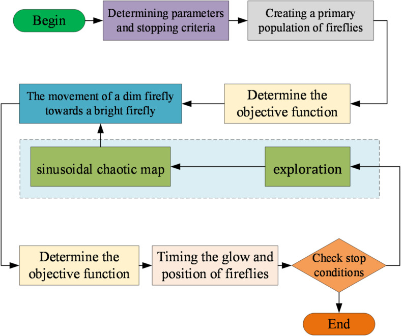
Block diagram of the PFF algorithm.
Therefore, this model will be able to model the effects of internal oscillations within the region and oscillations between regions. In this study, the second region or the third generator is first equipped with a classic PSS and then equipped with the proposed ANN/PFF-PSS, so that the superiority of this display the type of PSS in different working conditions.
The neural network used in this PSS is a type of the classic feed forward network with back propagation training. ANN inputs are active power and reactive power and its outputs are a PID controller parameters, including i.e., Kp, Ki, Kd. These parameters are obtained based on the proposed PFF for a series of specific inputs.
The results show that ANN/PFF-PSS shows good performance in MMPS. The ANN used in this article includes two inputs, three outputs and 15 neurons in the hidden layer with a purelin function in the hidden layer and a linear function in the last layer.
Methodology
Promoted firefly algorithm
Introduction
The firefly algorithm, introduced by Yang in 2008, is a revolutionary approach to problem-solving inspired by the way fireflies light up in the dark. The Firefly Algorithm has been found to have a better performance for finding the general optimal point in comparison with the bird algorithm and the genetic algorithm42.
In 2010, the creator of the Firefly Algorithm published the results of other accepted tests which validated the algorithm and found it to be faster than other algorithms43. This algorithm uses changes in light intensity and attractiveness in its optimization process and the objective function can be proportional to the brightness of fireflies44. Additionally, the attractiveness of a firefly is determined by the luminance or light intensity of the objective function, which can be simply expressed in genetic algorithms45. The primary purpose of fireflies is to emit light as a signaling system to attract other fireflies. The maximum brightness of a firefly at a single location X can be proportional to the highest value of the objective function in the most straightforward optimization problems. The further away an object is from its light source, the lower the intensity of the light it receives. Light is also absorbed in the environment, so the attractiveness of an object should be adjusted to reflect this absorption level. Generally, the light intensity  changes in a continuous and exponential manner relative to the distance
  .
.
 |
20 |
where, describes the primary light intensity and is the light absorption coefficient. The more light a firefly emits, the more attraction it has to its surroundings. By using Eq. (21), we can now accurately measure the attraction value β of a firefly.
 |
21 |
 is the irresistible value at a distance of zero. By using the Cartesian coordinates and the Eq. (22), you can quickly and accurately calculate the distance between fireflies i, j in
  and
and  .
.
 |
22 |
Utilize the power of  , part of firefly i, and observe as fireflies irresistibly move towards brighter ones! With each stage, the displacement of the attracted worm i towards the more attractive firefly j is determined by Eq. (23).
 |
23 |
The second part of the equation has to do with attraction, while the third part is unpredictable, varying according to a vector that follows the normal distribution. When dealing with various dimensions, it is recommended to use a scaling vector,  , for the input parameters to the algorithm, instead of
  , when the size values of each dimension differ significantly (e.g., from 10 to 105 in one dimension and from 10 to 103 in another). Otherwise, the standard values
  ,
,  , and
, and  can be used in most applications.
By normalizing the input parameters of this article to the interval of [−1,1], not only has the speed of training improved and the error of the neural network been reduced, but the assimilation of the data created has caused changes in different dimensions. The parameter  determines the alteration of attractiveness, and its value dictates the speed of convergence and behavior of the firefly algorithm. In theory, γ should be in the range of [0, ∞), however, in practice, it is set to either 0 or 1 depending on the system being optimized.
When  is 0, the attractiveness
  is equal to
  , which can be likened to saying that the intensity of light does not diminish in an ideal space; therefore, a bright firefly can be seen at any point in the domain, leading to the optimum (usually the overall optimum) quickly being reached, which is akin to a certain mode of the bird’s flight algorithm. This can also be modified to reach different optimal points (if they exist) by changing
  increasing the value causes the attractiveness to decrease, preventing the worms from being drawn to local optima. If there are several optimal points in the area the worms are released in and the worm population is larger than the number of optimal points, no optimal point will be left unnoticed.
Proposed method
The Firefly Algorithm is an evolutionary optimization technique that can be used for a wide variety of problems. It has been shown to perform well on challenging optimization tasks, and it has the potential to outperform conventional optimization methods. Improving the firefly algorithm would enable it to more accurately and efficiently find the optimal solution to a given problem46. Improvements can be made by increasing the accuracy of the simulation through better parameter tuning, increasing the number of simulations run, and developing new strategies for the type of problem being solved.
By utilizing the original FA, you can take advantage of three distinct phases: initialization, searching, and finalizing. The FA method further improves on this technique by introducing the primary firefly swarm and evaluating the objective function for each individual butterfly. Setting algorithm parameters is also made easy with this approach47.
After carefully setting the algorithm parameters, the optimization is underway. To begin, fireflies are randomly generated in the search space with more exploration and commence their journey to find a better location. As they move and explore, cost values are evaluated. Then, the current location is calculated using this formula:
 |
24 |
where,  illustrates the solution vector
  of the
  firefly,
  is the optimal solution for iteration
  ,
,  displays an arbitrary number between 0 and 1,
  describes the scent of the
  firefly.
A possible way chaos theory can be used to improve the firefly algorithm is by introducing chaotic search strategies into the firefly algorithm. Chaotic search strategies enable the algorithm to explore a wider range of solutions than traditional methods and can help in optimizing complex problems faster. This is particularly useful for finding global minima in difficult optimization problems. Additionally, chaos theory can also be used to create an adaptive learning process which can adjust and adjust its exploration of the search space based on feedback from past searches. This could help the firefly algorithm quickly identify suitable candidate solutions.
This feature drastically enhances the distribution of the points in the search space, making them much simpler and more evenly distributed. As a result, this will speed up the convergence rate of the FA thanks to the general form of chaos theory. The following is a generalized statement of the chaos theory that will surely convince you of its validity:
 |
25 |
where,  describes the chaotic model generator function, and
  , where, l describes the map dimension.
Utilizing the sinusoidal chaotic map as the key parameters here provides proper results, such that:
 |
26 |
where,  is a constant adjustable value between 0 and 1 (here,
  ), and
  The block diagram of the proposed (PFF) promoted firefly algorithm is shown in Fig. 7.
Optimal artificial neural network based on PFF algorithm
An artificial neural network is a type of computer algorithm that is modeled after biological neural networks. It is an interconnected group of artificial neurons which simulate the functions of biological neurons in a human brain. These networks are used to solve complex problems and optimize large datasets by analyzing patterns and making predictions based on observations48. Artificial neural networks can learn from data, recognize patterns, and make decisions with minimal human intervention.
They have the ability to identify complex relationships between inputs and outputs and generate insights which are otherwise difficult to obtain49. Artificial neural networks have been used in many different applications such as machine vision, speech recognition, natural language processing, bioinformatics, robotics and autonomous vehicle control.
Assuming the neuron’s network function,  , is dependent on inputs,
  , and their weights,
  , mathematical modeling of a neuron in the neural network is essential.
 |
27 |
where,  signifies the activation function.
Back propagation is the most popular technique for feed forward networks, utilizing the power of gradient descent and the activation function. With this powerful method, the network can measure its error and adjust the weights to eventually reach the desired outcome. However, this process requires a great deal of iterations.
The gradient descent algorithm is plagued by the problem of becoming trapped in local optima, which is heavily dependent on the initial weight settings. To combat this issue, an innovative optimization method is proposed and implemented instead of gradient descent, thereby eliminating this obstacle.
Employing the PFF algorithm to select optimal values for the neural networks allows us to utilize and train the network with maximum efficiency. Utilizing the mean squared error (MSE) as our cost function will ensure that we receive the optimal value of weights every time.
 |
28 |
By training with  samples and using
  nodes in the output, we can successfully generate a real output
  that matches our desired output
  . In this study, the promoted firefly algorithm has been used for this purpose.
Simulation results
Model of the network connected to the infinite bus
In order to accurately assess the impact of infinite bus on the multi-machine power network, this paper will compare the results obtained with a similar network without infinite bus. To do this, we have chosen a network featuring three generators, as shown in Fig. 8. By closely examining the effects of an infinite bus on a multi-machine power network, we can gain invaluable insight into its operation and performance. Figure 8 shows the power system with three generators.
Fig. 8.

Power system with three generators.
By simply flipping a switch, the B-4 bus can be transformed into an infinity shin. All parameters of the generator, transmission lines and controllers of the governor and excitation field have been thoroughly tested in this network. To demonstrate how model generator behaves when connected to an infinite bus, a three-phase short circuit was simulated at the moment of 0.2 s for a duration of 0.1 s.
The B-4 bus can be transformed into an infinity bus by a switch. Figures 9 and 10 show the results of the load angle for the mentioned model. The results again show that model 3 is close to model 1 in terms of accuracy and model 4 does not provide adequate accuracy.
Fig. 9.

Comparison of the results for the load angle ( –
–  ).
).
Fig. 10.

Comparison of the results for the load angle ( –
–  ) for MMPSW and MMPS.
Load angle control
The three-generator model has been used in MMPS simulation and ANN/PFF-PSS is designed in such a way to give a suitable solution in three-phase short circuit conditions and normal conditions50. Three-phase short circuit to MMPS with three generators presented in Fig. 7.
In the state without connection to the infinite grid has been applied to bus B-4 at a moment of 0.2 s for a duration of 0.1 s for different working conditions. It is assumed that the active power is from 0 PU to 1 PU and the reactive power can change from − 0.2 to 0.2.
The controller parameters should be set in such a way that the sum of the squared errors (ISE) for changing the load angle and the terminal voltage of the generator equipped with PSS becomes the lowest value. the mathematical model of ISE is given below:
 |
29 |
where,  and
and  represent the lowest value of the sum of squares of the load angle error and the lowest value of the sum of the squares of the generator terminal voltage error, respectively. Also,
  and
and  describe the required weights.
One of the traditional methods to obtain suitable coefficients of the PID controller which can also provide an acceptable solution is to change the coefficients of the controller in the defined range to obtain Bringing ISE.
Utilizing the proposed Promoted Firefly Algorithm to obtain the necessary coefficients of the controller, we can create a Power System Stabilizer that will provide an ideal response for every expected load in the generator’s defined intervals.
Then through training the network according to each specific load and extracting the controller coefficients, the neural network will have the ability to respond to any random load to provide the best controller coefficients.
Figure 11 show the comparison of the results for the generator equipped with classic PSS, ANN/PFF-PSS, and without PSS. These results show that ANN/PFF-PSS is able to reduce the fluctuations of the load angle within the region and between regions without having a destructive effect during voltage fluctuations.
Fig. 11.

Load angle response to three-phase short circuit for p = 1 and q = 0.2 in inter-zone mode.
As can be seen from Fig. 11, using both the proposed ANN/PFF-PSS and classic PSS for load angle response in three-phase systems are efficient for this purpose; however, ANN/PFF-PSS provide better results than the classic model of PSS for this system. Indeed, ANN/PFF-PSS is computational decision-making and rely on an iterative trial-and-error approach to find a set of near-optimal solutions.
Load angle and voltage response under three-phase short circuit
The whole four generator system (MMPS) was subjected to three-phase short circuit at B-5 bus at t = 0.15 s for a time span of 0.05 s. Here were the key metrics that were reviewed (Table 5):
Table 5.
Load angle and voltage response under three-phase short circuit.
| Parameter | Without PSS | Classic PSS | ANN/PFF-PSS | Improvement (%) |
|---|---|---|---|---|
| Peak Overshoot (δ₁–δ₂) (rad) | 0.45 | 0.28 | 0.18 | 35.7% ↓ |
| Settling Time (δ₁–δ₃) (s) | 3.2 | 2.1 | 1.5 | 28.6% ↓ |
| Voltage Dip (Bus B) (p.u.) | 0.65 | 0.75 | 0.82 | 9.3% ↑ |
| Oscillation Damping (δ₁–δ₄) | Poor | Moderate | High | > 40% better damping |
Simulation results confirm that the proposed ANN/PFF-PSS outperforms the classic PSS as it effectively minimizes the peak overshoot and settling time, leading to faster and more stable voltage recovery with more than 40% damping ratio improvement thus reducing inter-area oscillations and enhancing the overall system performance.
Discussions
This technique can be employed in the design of power system stabilizers, particularly in multi-machine systems, as they are able to solve complicated optimization problems quickly and accurately with relatively fewer variables.
On the other hand, classic power system stabilizers employ analytical methods such as frequency domain analysis to characterize and design power system stabilizers. The classic PSS is able to model complex interdependencies between the power system elements, as well as accurately predict the effects of damping controller on system performance. Overall, it can be concluded that both types of Power System Stabilizers have demonstrated good results when implemented for load angle response in three-phase systems. The choice between the two depends on the complexity of the problem, the preference of the engineer, and the design constraints. ANN/PFF-PSS provide a more powerful optimization capability, while classic PSS are more suitable for simpler problems with fewer variables.
Conclusion
Generator modeling and stabilizer design in multi-machine power systems are two of the most difficult tasks in power system engineering. Metaheuristics and artificial neural networks (ANNs) can be used to model generators and design stabilizers more effectively. Metaheuristics are optimization techniques that simulate natural processes such as evolution, mutation, and recombination to find desirable solutions to complex problems. ANNs use parallel computing to identify complex patterns in large amounts of data, and can be used to model nonlinearities in power systems. By combining metaheuristics and ANNs, engineers can identify suitable generator models and design efficient stabilizers for multi-machine power systems. Metaheuristics can be used to search for the optimal combination of parameters while ANNs can be used to evaluate and improve the performance of the generator models. Furthermore, ANNs can be used to identify the most suitable stabilizer design based on an optimization process. This process can help improve grid stability and reduce the need for costly preventive maintenance measures. Here, A generator model was simulated in studying the dynamics of power systems. Two similar multi-machine networks, one connected to the infinite bus and the other without connection to the infinite network, were simulated. The results of these two networks were compared with each other. The obtained results showed the remarkable effect of infinite shear. These results showed that the design performance of stabilizers was strongly influenced by the generator and network model. Realizing this vulnerability, the stabilizer designed in a network without connection to the infinite bus was designed. The PSS was designed with PID controller and ANN neural networks, which was introduced as -ANNS. The parameters of this controller were obtained based on a new promoted version of the firefly (PFF)algorithm. The results obtained in the three-phase short circuit test with the proposed ANN/PFF-PSS and a classic PSS show that the designed model is able to reduce the fluctuations created within the area and between areas without having a destructive effect on voltage fluctuations. The advantage of these PSSs compared to adaptive PSSs was in their simplicity and speed of operation. Their disadvantage was the adjustment of ANN parameters according to the shape of the power grid, and because these changes were already known and take place in predetermined time processes, there will always be enough opportunity to adjust the parameters. The results for three-phase short-circuit conditions showed that compared with the conventional PSS, ANN/PFF-PSS reduces load angle overshoot (35.7%) and settling time (28.6%). It also improved the recovery of voltage by 9.3%. This confirms the robustness of the proposed stabilizer and establishes that it is preferred for damping not only inter-area but also intra-area oscillations in the complex power system.
Author contributions
Xiujun Nie, Nan Sun, Buqin Wang and Ganbar Akbari wrote the main manuscript text and prepared figures. All authors reviewed the manuscript.
Data availability
All data generated or analysed during this study are included in this published article.
Declarations
Competing interests
The authors declare no competing interests.
Footnotes
Publisher’s note
Springer Nature remains neutral with regard to jurisdictional claims in published maps and institutional affiliations.
Contributor Information
Nan Sun, Email: sunn425@126.com.
Ganbar Akbari, Email: ganbarakbari0@gmail.com.
References
- 1.Zhu, L. et al. Multi-criteria evaluation and optimization of a novel thermodynamic cycle based on a wind farm, Kalina cycle and storage system: an effort to improve efficiency and sustainability. Sustain. Cities Soc.96, 104718 (2023). [Google Scholar]
- 2.Bo, G. et al. Optimum structure of a combined wind/photovoltaic/fuel cell-based on amended Dragon fly optimization algorithm: a case study. Energy Sour. Part A Recover. Utilization Environ. Eff.44 (3), 7109–7131 (2022). [Google Scholar]
- 3.Dasu, B., Sivakumar, M. & Srinivasarao, R. Interconnected multi-machine power system stabilizer design using Whale optimization algorithm. Prot. Control Mod. Power Syst.4, 1–11 (2019). [Google Scholar]
- 4.Cai, W. et al. Optimal bidding and offering strategies of compressed air energy storage: A hybrid robust-stochastic approach. Renew. Energy. 143, 1–8 (2019). [Google Scholar]
- 5.Cao, Y. et al. Optimal operation of CCHP and renewable generation-based energy hub considering environmental perspective: an epsilon constraint and fuzzy methods. Sustain. Energy Grids Netw.20, 100274 (2019). [Google Scholar]
- 6.Butti, D., Mangipudi, S. K. & Rayapudi, S. R. An improved Whale optimization algorithm for the design of multi-machine power system stabilizer. Int. Trans. Electr. Energy Syst.30 (5), e12314 (2020). [Google Scholar]
- 7.Chen, L. et al. Optimal modeling of combined cooling, heating, and power systems using developed African Vulture optimization: a case study in watersport complex. Energy Sour. Part A Recover. Utilization Environ. Eff.44 (2), 4296–4317 (2022). [Google Scholar]
- 8.Dehghani, M. et al. Blockchain-based Securing of data exchange in a power transmission system considering congestion management and social welfare. Sustainability13 (1), 90 (2021). [Google Scholar]
- 9.Yuan, K. et al. Optimal parameters estimation of the proton exchange membrane fuel cell stacks using a combined Owl search algorithm. Energy Sour. Part A Recover. Utilization Environ. Eff.45(4), 11712–11732 (2023). [Google Scholar]
- 10.Latif, S. et al. Intelligent design of multi-machine power system stabilizers (PSSs) using improved particle swarm optimization. Electronics11 (6), 946 (2022). [Google Scholar]
- 11.Eslami, M. et al. A new formulation to reduce the number of variables and constraints to expedite SCUC in bulky power systems. Proc. Natl. Acad. Sci. India Sect. A: Phys. Sci.89, 311–321 (2019). [Google Scholar]
- 12.Fan, X. et al. High voltage gain DC/DC converter using coupled inductor and VM techniques. IEEE Access.8, 131975–131987 (2020). [Google Scholar]
- 13.Sabo, A. et al. Application of neuro-fuzzy controller to replace SMIB and interconnected multi-machine power system stabilizers. Sustainability12 (22), 9591 (2020). [Google Scholar]
- 14.Ghiasi, M., Ghadimi, N. & Ahmadinia, E. An analytical methodology for reliability assessment and failure analysis in distributed power system. SN Appl. Sci.1 (1), 44 (2019). [Google Scholar]
- 15.Zehao, W. et al. Optimal economic model of a combined renewable energy system utilizing modified. Sustain. Energy Technol. Assess.74, 104186 (2025). [Google Scholar]
- 16.Han, E. & Ghadimi, N. Model identification of proton-exchange membrane fuel cells based on a hybrid convolutional neural network and extreme learning machine optimized by improved honey Badger algorithm. Sustain. Energy Technol. Assess.52, 102005 (2022). [Google Scholar]
- 17.La, C. & Balachander, K. Design of power system stabilizer for multi-machine systems using modified swarm optimization algorithm with wind energy generation. J. Green. Eng.11 (1), 156–178 (2021). [Google Scholar]
- 18.Gong, Z., Li, L. & Ghadimi, N. SOFC stack modeling: a hybrid RBF-ANN and flexible Al-Biruni Earth radius optimization approach. Int. J. Low-Carbon Technol.19, 1337–1350 (2024). [Google Scholar]
- 19.Ghiasi, M. et al. Enhancing power grid stability: design and integration of a fast bus tripping system in protection relays. IEEE Trans. Consum. Electron. 10.1109/TCE.2024.3519389 (2024).
- 20.Chang, L., Wu, Z. & Ghadimi, N. A new biomass-based hybrid energy system integrated with a flue gas condensation process and energy storage option: an effort to mitigate environmental hazards. Process Saf. Environ. Prot.177, 959–975 (2023). [Google Scholar]
- 21.Kumar, R., Mohanty, S. & Verma, M. Design and optimal location of power system stabilizer in the multi-machine power network. IETE J. Res. 1–20. 10.1080/03772063.2023.2175056 (2023).
- 22.Dasu, B., Mangipudi, S. & Rayapudi, S. Small signal stability enhancement of a large scale power system using a bio-inspired Whale optimization algorithm. Prot. Control Mod. Power Syst.6 (1), 1–17 (2021). [Google Scholar]
- 23.Devarapalli, R. et al. Amended GWO approach based multi-machine power system stability enhancement. ISA Trans.109, 152–174 (2021). [DOI] [PubMed] [Google Scholar]
- 24.Zadehbagheri, M. et al. Designing a power system stabilizer using a hybrid algorithm by genetics and bacteria for the multi-machine power system. Bull. Electr. Eng. Inf.12 (3), 1318–1331 (2023). [Google Scholar]
- 25.Dasu, B., Sivakumar, M. & Srinivasarao, R. Interconnected multi-machine power system stabilizer design using Whale optimization algorithm. Prot. Control Mod. Power Syst.4 (1), 1–11 (2019). [Google Scholar]
- 26.Chaib, L. et al. Robust design of power system stabilizers using improved Harris Hawk optimizer for interconnected power system. Sustainability13 (21), 11776 (2021). [Google Scholar]
- 27.Zehao, Wang, et al. Optimal economic model of a combined renewable energy system utilizing Modified.Sustainable Energy Technologies and Assessments 74, 104186 (2025).
- 28.Yanda, L., Yuwei, Z. & Razmjooy, N. Optimal arrangement of a micro-CHP system in the presence of fuel cell-heat pump based on metaheuristics. Int. J. Ambient Energy 1–12 (2020).
- 29.Bahmanyar, D., Razmjooy, N. & Mirjalili, S. Multi-objective scheduling of IoT-enabled smart homes for energy management based on arithmetic optimization algorithm: A Node-RED and NodeMCU module-based technique. Knowl. Based Syst.247, 108762 (2022). [Google Scholar]
- 30.Cao, Y. et al. Experimental modeling of PEM fuel cells using a new improved seagull optimization algorithm. Energy Rep.5, 1616–1625 (2019). [Google Scholar]
- 31.Fan, X. et al. Multi-objective optimization for the proper selection of the best heat pump technology in a fuel cell-heat pump micro-CHP system. Energy Rep.6, 325–335 (2020). [Google Scholar]
- 32.Gong, W. & razmjooy, N. A new optimisation algorithm based on OCM and PCM solution through energy reserve. Int. J. Ambient Energy. 43 (1), 2299–2312 (2020). [Google Scholar]
- 33.Guo, Y. et al. An optimal configuration for a battery and PEM fuel cell-based hybrid energy system using developed Krill herd optimization algorithm for locomotive application. Energy Rep.6, 885–894 (2020). [Google Scholar]
- 34.Hosseini, H. et al. Hybrid energy production system with PV Array and wind turbine and pitch angle optimal control by genetic algorithm. J. Electr. Eng. Technol.1(1), (2011).
- 35.Sun, L. et al. Exergy analysis of a fuel cell power system and optimizing it with Fractional-order Coyote optimization algorithm. Energy Rep.7, 7424–7433 (2021). [Google Scholar]
- 36.Khalilpour, M. & Razmjooy, N. Congestion management role in optimal bidding strategy using imperialist competitive algorithm. Majlesi J. Energy Manage.1(2), (2012).
- 37.Rezaie, M. et al. Model parameters Estimation of the proton exchange membrane fuel cell by a modified golden Jackal optimization. Sustain. Energy Technol. Assess.53, 102657 (2022). [Google Scholar]
- 38.Fang, L., Li, D. & Qu, R. Torque improvement of Vernier permanent magnet machine with larger rotor pole pairs than stator teeth number. IEEE Trans. Industr. Electron.70 (12), 12648–12659 (2023). [Google Scholar]
- 39.Rong, Q. et al. Asymmetric sampling disturbance-based universal impedance measurement method for converters. IEEE Trans. Power Electron. 10.1109/TPEL.2025.3565789 (2024).
- 40.Yang, M. et al. Investigating black-box model for wind power forecasting using local interpretable model-agnostic explanations algorithm: why should a model be trusted? CSEE J. Power Energy Syst. 10.17775/CSEEJPES.2021.07470 (2023).
- 41.Besmi, M. R. Generator Power System Modelling and Stabiliser Design Using Genetic and Neural Methods (University of Newcastle upon Tyne, 1996).
- 42.Chaurasia, G. S. et al. A meta-heuristic firefly algorithm based smart control strategy and analysis of a grid connected hybrid photovoltaic/wind distributed generation system. Sol. Energy. 150, 265–274 (2017). [Google Scholar]
- 43.George, G. & Parthiban, L. Multi objective hybridized firefly algorithm with group search optimization for data clustering. In 2015 IEEE International Conference on Research in Computational Intelligence and Communication Networks (ICRCICN) (IEEE, 2015).
- 44.Gong, Ziqian, Lu Li, and Noradin Ghadimi. SOFC stack modeling: a hybrid RBF-ANN and flexible Al-Biruni Earthradius optimization approach.International Journal of Low-Carbon Technologies 19 1337–1350 (2024).
- 45.Kashikolaei, S. M. G. et al. An enhancement of task scheduling in cloud computing based on imperialist competitive algorithm and firefly algorithm. J. Supercomput.76, 6302–6329 (2020). [Google Scholar]
- 46.Bacanin, N. et al. A novel firefly algorithm approach for efficient feature selection with COVID-19 dataset. Microprocess. Microsyst. 104778. 10.1016/j.micpro.2023.104778 (2023). [DOI] [PMC free article] [PubMed]
- 47.Tiwari, A. & Chaturvedi, A. Automatic EEG channel selection for multiclass brain-computer interface classification using multiobjective improved firefly algorithm. Multimedia Tools Appl.82 (4), 5405–5433 (2023). [Google Scholar]
- 48.Zhang, J. et al. Series–shunt multiport soft normally open points. IEEE Trans. Industr. Electron.70 (11), 10811–10821 (2022). [Google Scholar]
- 49.Ni, L. et al. An explainable neural network integrating Jiles-Atherton and nonlinear auto-regressive exogenous models for modeling universal hysteresis. Eng. Appl. Artif. Intell.136, 108904 (2024). [Google Scholar]
- 50.Li, N. et al. Single-degree-of-freedom hybrid modulation strategy and light-load efficiency optimization for dual-active-bridge converter. IEEE J. Emerg. Sel. Top. Power Electron. 10.1109/JESTPE.2024.3396340 (2024).
Associated Data
This section collects any data citations, data availability statements, or supplementary materials included in this article.
Data Availability Statement
All data generated or analysed during this study are included in this published article.