

Abstract
This research outlines the results on implementing a Machine Learning (ML) approach to improve the throughput of Multiple-Input Multiple-Output (MIMO) based 5G millimeter wave applications. The research will cover frequencies between 28 and 38 GHz, significantly affecting high-band 5G applications. We have chosen to employ a Rogers RT 5880 material with a low loss as the substrate layer to reduce the antenna size. In addition to being small, the recommended design has a maximum gain of 10.14 dB, better isolation than 29 dB, and wide bandwidth, ranging from 27.2 GHz to 32.2 GHz & 36.5 GHz to 40.7 GHz. Advanced design system (ADS) is used to make a circuit like the suggested microstrip patch antenna (MPA) to compare the reflection coefficient from CST. The approach of supervised regression machine learning is applied to accurately forecast the antenna’s gain. Among the five different regression machine learning models considered, it was discovered that the Random Forest Regression (RFR) model performed the best in accuracy and achieved the lowest error when predicting gain. This article explores many approaches, including simulation, integration of an RLC-equivalent circuit model, and multiple regression models, to evaluate the suitability of an antenna for its 5G applications.
Keywords: Dual-Band, 28/38 GHz, Array antenna, MIMO, mm-Wave, High-Gain, Parasitic decoupling structure, Defected ground, Machine learning
Subject terms: Electrical and electronic engineering; Design, synthesis and processing; Optics and photonics; Metamaterials
Introduction
The exponential growth in wireless communication demand, driven by data-intensive applications and the proliferation of connected devices, has catalyzed the development of fifth-generation (5G) and future sixth-generation (6G) communication networks. These technologies require high-speed, low-latency, and high-capacity data transmission, necessitating antennas capable of operating effectively at millimeter-wave (mm Wave) frequencies1. Specifically, the 28 GHz and 38 GHz bands have emerged as promising frequency candidates for 5G and 6G applications due to their capability to support high data rates and densely packed urban environments. As a result, designing antennas that can operate efficiently within these bands has become a key area of focus. Microstrip Patch Antennas (MPAs) have gained substantial attention in this context due to their compact size, low weight, ease of fabrication, and compatibility with planar and non-planar surfaces, making them ideal for integration into mm Wave devices2. However, achieving high gain, enhanced directivity, and stable radiation characteristics at 28 GHz and 38 GHz frequencies presents specific challenges. These limitations are inherent to conventional MPAs and must be addressed to ensure optimal performance in next-generation networks3.
This paper introduces a dual-band MPA designed specifically for operation at 28 GHz and 38 GHz, targeting the primary mm Wave frequency bands anticipated for 5G and 6G networks. This MPA design is optimized to achieve desired performance metrics across both frequency bands, such as minimal return loss, optimal impedance matching, and consistent gain4. To further improve performance, particularly in increased capacity and reduced multipath fading, we extended the single MPA design into a 1 × 2 array configuration, enhancing gain and beamforming capabilities. Building upon the array configuration, a 4-port MIMO (Multiple-Input Multiple-Output) configuration was implemented, capitalizing on spatial diversity and reducing signal degradation, both are essential for maintaining high data rates and reliability in complex urban environments5.
The array and MIMO configurations were meticulously designed to maintain low inter-element spacing, minimizing mutual coupling and ensuring high isolation between ports. This is critical in MIMO systems to avoid interference and signal degradation. Performance simulations were conducted using CST Microwave Studio, allowing for an in-depth evaluation of critical parameters, including return loss, gain, radiation pattern, and isolation in the MIMO setup6. The simulation results demonstrate that the proposed MPA configurations satisfy the stringent requirements for 5G and 6G applications, achieving high gain and isolation while maintaining dual-band functionality at 28 GHz and 38 GHz7.
In addition to simulation-based evaluations, a machine learning (ML)-based predictive model is employed to enhance the efficiency of performance analysis8. ML techniques have demonstrated significant potential in antenna design, enabling rapid optimization and accurate prediction of key performance metrics without requiring extensive electromagnetic simulations9. Supervised learning algorithms are utilized to train regression models on simulated data, facilitating precise estimation of parameters such as return loss, gain, and efficiency. This data-driven approach aids in identifying optimal design configurations, reducing computational complexity, and accelerating the antenna design process10. Moreover, ML-based analysis provides deeper insights into the complex relationships between design parameters, contributing to improved adaptability and scalability for future wireless communication applications11. By integrating ML techniques, the proposed methodology not only enhances computational efficiency but also refines the design process for next-generation MIMO antennas.
This paper makes several key contributions to the field of mm Wave antenna design for advanced communication networks:
Development of a dual-band MPA tailored for the 28 GHz and 38 GHz bands, optimizing performance metrics critical to 5G/6G applications.
Design and implement a 1 × 2 array configuration, significantly enhancing gain and directivity.
Expansion to a 4-port MIMO configuration, improving channel capacity and reliability through spatial diversity while achieving low mutual coupling and high port isolation.
A conceptual comparison of various ongoing initiatives is presented in Table 1. Its gain of 10.14 dB is derived from the CST simulation of the proposed MIMO antenna and is greater than all of the references9–19, which modeled gains of 7.9 dB, 5.7 dB, 1.83 dB, 8.27 dB, 6.6 dB, 8.4 dB, 7.8 dB, 8.24 dB, 4 dB and 10 dB respectively. The proposed antenna realizes mass over 92% efficiency, whereas the reference works12–18 achieves 85%, 84%, 78%, 88.25%, 85%, 91.7% and 65% radiation efficiency respectively. There is more than 28 dB of isolation in the proposed design. There is a wide range of isolation levels that are referenced as mentioned earlier, levels of > 27 dB, > 25 dB, > 20 dB, > 26 dB, > 28 dB, > 25 dB, > 20 dB, > 30, >27 dB, > 25 dB and > 19 dB was registered. Compared to other alternatives, the suggested MIMO antenna demonstrated better performance metrics, such as a DG higher than 9.92 and an ECC lower than 0.015. However, the RLC equivalent circuit results are indispensable to the described architecture even though the sources do not utilize them. While references19,20 utilize machine learning techniques, their overall performance in terms of bandwidth, gain, and isolation is inferior to the proposed design. The comparison table demonstrates the superior performance of the proposed antenna. Unlike existing designs, it achieves a well-balanced trade-off between the key parameters, ensuring optimal MIMO performance. These results validate the effectiveness of the proposed design for high-performance 5G MIMO applications.22
Table 1.
Comparison of performance with related works.
| Refs. | Resonant fr | Operating range |
BW | Substrate Material | Board Size | Port | Gain (db) |
Isolation (dB) | ECC DG (dB) |
Efficiency | RLC & Machine Learning |
|---|---|---|---|---|---|---|---|---|---|---|---|
| 12 | 28, 38 |
27.6–28.6/ 37.4–38.6 |
1, 1.2 |
Rogers-5880 | 2.24λ°×2.1λ° | 4 |
7.1, 7.9 |
> 27 | < 0.001, NA | > 85% | No/ No |
| 13 | 28, 38 | NA |
1.39, 3.33 |
Duroid 5880 | 3.87λ°×0.93λ° | 4 |
5.59, 5.7 |
> 25 | < 0.001/ >9.96 | > 84% | No/ No |
| 14 | 28, 38 |
26.65–29.2, 36.95–39.05 |
2.55, 2.1 |
Duroid 5880 |
1.3λ°× 2.42λ° |
2 |
1.27, 1.83 |
> 20 | < 0.001/>9.99 |
78%, 76% |
No/ No |
| 15 | 28, 38 | NA |
1.06, 1.43 |
Rogers 5880 | 5.13λ°×10.2λ° | 4 |
7.95, 8.27 |
> 26 | < 0.001/ NA | 88.25% | No/ No |
| 16 | 28, 38 | NA |
1.23, 1.06 |
Rogers Ro3003TM | 0.7λ° × 0.82λ° | 2 |
6.6, 5.86 |
> 28 | < 0.005/<9 |
80%, 85% |
No/ No |
| 17 | 28, 38 | 26.6–29, 37.3–39.3 |
2.4, 2 |
Rogers RT5880 | 1.23λ° ×1.23λ° | 4 |
8.4, 6.02 |
> 25 | 0.005, ≈ 10 | 91.7%,88.6% | No/ No |
| 18 | 28, 38 |
24–28, 37–40 |
4, 3 |
FR4 | 4.66λ°×4.66λ° | 4 |
7.8, 4.4 |
> 20 | 0.01/9.99 |
65%, 49% |
No/ No |
| 21 | 28, 38 |
24-28.8, 36.6–40.8 |
4.8, 4.2 |
RT5880 | 0.82λ°×1.6λ° | 2 | 7.8, 6 |
> 30, >28 |
0.0001, > 9.99 | NA | No/ No |
| 22 | 24, 32 | NA | 4.24,0.46 | Rogers RT5880 | 1.6λ° ×1.6 λ° | 4 | 8.24 | -27 | 0.0006,9.97 | 94% | No/ No |
| 19 | 3.8 | 3-4.2 | 1.2 | Rogers RT5880 | 0.76*1.52 | 2 | 4 | -25 |
0.005, 9.99 |
95% | No/Yes |
| 20 | 27.75 | 27.5-28.35 | 0.85 | Rogers RT5880 | 20*20 | 2 | 10 | -19 |
0.002, 9.98 |
NA | No/Yes |
| Simulated | 28, 38 |
27.2–32.2, 36.5–40.7 |
5, 4.2 |
Rogers RT5880 | 3.34λ° ×3.34λ° | 4 |
10.14, 9.5 |
> 29, >29 |
< 0.007,>9.96 |
> 92%, >91 |
Yes/Yes |
| Measured |
28.3, 37.9 |
26.6–32.3, 33.2–39.9 |
5.7, 6.7 |
10.1, 9.3 | > 34.2, 35.8 | < 0.015,>9.92 |
> 91%, >89% |
Design methodology
This work presents a novel antenna design incorporating a Parasitic Decoupling Structure and a Defected Ground Slot. The frequencies at which our antenna operates are 28 and 38 GHz. The section discusses the evolutionary development of the proposed antenna, highlighting its transition from simple functionality to advanced, high-performance systems. The material used as a substrate is Rogers RT5880, with a dielectric constant of 2.2 and a loss tangent of 0.0009. Both the ground and radiator are composed of annealed copper.
Single element
The subsequent section reviews the crucial stages in the evolution of the single-element antenna. Achieving optimal performance resulted from a systematic and iterative methodology that evolved through four major stages. Figure 1(a) illustrates the evolution of the single-element antenna, while Fig. 1(b) presents the S-parameter at each optimization stage. In the initial stage, we design a rectangular patch antenna and a feedline, utilizing a matching network for the feedline design. To enhance the efficiency and radiating properties of the antenna, we incorporate two insets on either side of the feed and introduce an L-shaped slot on the left side and a mirrored L-shaped slot on the right side. It results in single-band resonance at 27.826 GHz, with a bandwidth of 1.18 GHz.
Fig. 1.

(a) The Different designing stages of our single-element antenna and (b) the S11 curve for each stage.
However, the return loss results were initially inadequate. In the second phase, two square-shaped slots rotated at 45 degrees were introduced, improving return loss; however, the resonance shifted away from the target frequency of 28 GHz. In the third phase, an iterative refinement was conducted by adding a T-shaped slot at the centre of the radiator. This adjustment resulted in a resonance at 26.91 GHz and notable enhancements in return loss, although the resonance still deviated from the target frequency. Finally, in the fourth phase, two rectangular slots were incorporated on either side of the T-shaped slot. This modification successfully achieved a dual-band operation, with frequencies of 26.16 and 28.15 GHz and bandwidths of 0.45 GHz for the first band and 0.5 GHz for the second, effectively fulfilling all performance requirements. The detailed architecture of our proposed single-element antenna is illustrated in Fig. 2. The antenna maintains consistent dimensions of 5.22 × 6 mm² throughout each stage for the entire ground. Both the radiating patch and ground have a thickness of 0.035 mm, with the patch measuring 4.3 mm in width and 3.1 mm in length.
Fig. 2.

Our single-element antenna’s Front view with dimensions.
Array
The subsequent stage of progress entailed the utilization of arrays to enhance bandwidth and gain to facilitate superior control over signal propagation and reception23. The size of the array antenna is 15.4 × 17.4 mm2, and the patch size is the same as the single-element antenna. The suggested array antenna comprises two single-element antennas connected to the main feedline through a 70-ohm feedline and a 100-ohm feedline. The two antennae are spaced by 5.8 mm, denoted by d. Figure 3 shows the arrangement of the array antenna. Upon shifting to an array configuration, we obtained two frequencies of 28/38 GHz with the bandwidth of 1.4 GHz to 4.2 GHz, respectively. This bandwidth and gain increased in the array antenna compared to the single-element antenna.
Fig. 3.

Front view of the array antenna with dimensions.
Effect of various parameters on the antenna’s performance
Figure 4(a) highlights the significant impact of the distance between two patches in the array (d) on the antenna’s performance. For a gap of 5.8 mm, the resonant frequencies are 28 GHz and 38 GHz, with reflection coefficients of -42.45 dB and − 47.02 dB, respectively. A reduction in the distance to 4.8 mm shifts the frequencies to 28.32 GHz and 40.481 GHz, with reflection coefficients changing to -26.84 dB and − 20.38 dB. Conversely, increasing the distance to 6.8 mm results in a frequency shift of 27.67 GHz and 35.89 GHz, with reflection coefficients of -23.61 dB and − 45.42 dB. These results underscore the importance of our findings, as they show that both an increment and decrement of the value shift the resonance frequencies left and right, respectively, with a higher return loss for the first resonance frequency. It’s not worth it that the second band deviates more than the first frequency, further highlighting the significance of our findings.
Fig. 4.

S11 of the array antenna for different values (a) distance between patches, (b) feed length, and (c) AS7 slot length.
In Fig. 4 (b), as revealed by our research, our antenna’s performance depends on the feed length. Our antenna resonant frequencies for the proposed feed length (fl. = 5 mm) are 28 GHz and 38 GHz, with reflection coefficients of -42.45 and − 47.02 dB, respectively. After reducing the feed length to 4.5 mm, the frequencies change to 28.67 GHz and 38.77 GHz, and the corresponding reflection coefficients change to -20.8 & -24.271 dB. When increasing the feed length to 5.5 mm, the frequency and reflection coefficients are 27.284 GHz and 37.288 GHz with − 36.829 dB and − 32.871 dB, respectively. The results show that an increment and decrement of the value shift both the resonance frequencies left and right, respectively.
Figure 4(c) illustrates the antenna’s performance sensitivity to the As7 slot length. For the proposed slot length of 1.2 mm, the resonant frequencies are 28/38 GHz, and the reflection coefficients are − 42.45 dB and − 47.02 dB. A reduction in the slot length to 1 mm shifts the frequencies to 28.688 GHz and 38 GHz, so the reflection coefficients are − 32.41 dB and − 36.39 dB, respectively. However, increasing the slot length to 1.4 mm results in resonance frequencies of 26.54 GHz and 38 GHz, with a return loss of -37.69 dB and − 51 dB. This clearly demonstrates the sensitivity of the first band to the slot AS7 length, while the second band remains unchanged.
MIMO
Figure 5 depicts a unique integrated 4 × 4 MIMO antenna. The synergy significantly improved the antenna’s range and effectiveness in high-frequency communication systems. The size of the MIMO antenna is 37.8 × 37.8 mm2. Initially, the antennas are positioned near the midpoint of the board edge. Subsequently, they are relocated 7.65 mm away from the edge of the substrate to improve isolation24. The transmission coefficient for two different positions of the patches are shown in Fig. 6. The patch-to-patch distance is 8.5 mm.
Fig. 5.

Without PDS and DGS, The MIMO antenna Top and Bottom View.
Fig. 6.

Transmission Coefficient of the MIMO antenna for two different patch locations.
Parasitic decoupling structure with defected ground slot
An inherent issue in MIMO design is the phenomenon where the radiation of electromagnetic waves from one antenna causes interference in another antenna25. This leads to a decline in the signal-to-interference noise ratio (SINR) and the overall efficiency of the MIMO antenna. There are many methods to address this issue, including defective ground structure, parasitic elements, metamaterials, and metasurface. Figure 7 shows this antenna incorporates a parasitic decoupling structure and a defective ground slot to minimize the mutual coupling. A copper strip is meant to have a length of 5 mm and a width of 1 mm. Subsequently, two additional copper stripes are created on either side of it, measuring 5 mm and 6 mm in width and 1 mm in length, respectively. Ultimately, a 45-degree rotated square-shaped parasitic element is created precisely at the central location, with each side measuring 7.07 mm. The defective ground slots are formed to match the precise shape of the parasitic decoupling structure, except for the square-shaped element.
Fig. 7.

The proposed MIMO antenna with PDS and DGS Top and Bottom View.
The design parameters of the proposed antenna are as follows: Ws = 6, Ls = 5.22, Wp = 4.3, Lp = 3.1, S1 = 2.15 × 0.1, S2 = 0.1 × 1.4, S3 = 2 × 0.3, S4 = 1 × 0.3, S5 = 0.4 × 0.2, S6 = 0.57, S7 = 1.6 × 0.1, Inset = 0.6 × 0.06, Feedline = 1.8 × 0.4, Was = 17.4, Las = 15.4, As7 = 1.2 × 0.3, f1 = 5 × 0.7, f2 = 0.7 × 10.8, f3 = 5 × 2.5, Wm = 37.8, Lm = 37.8, d1 = 7.65, d2 = 8.5, d3 = 7.07, d4 = 5, d5 = 17, d6 = 6, d7 = 1, Metal thickness = 0.035, Substrate height = 0.8. All dimensions are in millimeters (mm) unless stated otherwise.
Result and analysis
This section examines the crucial parameter of the suggested MIMO antenna and aims to comprehend the antenna’s performance through an analysis of the results of the simulation and measurement.
Reflection and transmission coefficient
The S11 measures the proportion of the signal reflected to the source rather than being transmitted through the system26. In the results presented in Fig. 8, our proposed antenna’s performance is analyzed in terms of the reflection and transmission coefficients. A comparison of the simulated and measured results is made, with the simulated results also considering the parasitic decoupling structure (PDS) and defective ground slot (DGS). The simulated bandwidth range with PDS and DGS was 27.2–32.2 GHz and 36.5–40.7 GHz, respectively, with 5 GHz and 4.2 GHz bandwidths. Additionally, the isolation was maintained at 29 dB for both 28 GHz and 38 GHz. However, without PDS and DGS, the S11 width was unsatisfactory, with the bandwidth range observed to be 27.675–28.856 GHz. Regarding isolation, the values were 22.6 dB for 28 GHz and 21.9 dB for 38 GHz.
Fig. 8.

Measured and simulated (with and without PDS and DGS) (a) S11 and (b) The proposed MIMO Antenna Isolation curve.
The measured results exhibited significant improvements, showing increased bandwidth across the board. The measured bandwidth range was 26.6–32.3 GHz and 33.2–39.9 GHz, So the bandwidths are 5.7 and 6.7 GHz at 28 GHz and 38 GHz, respectively. The isolation also substantially enhanced, reaching 34.2 dB for 28 GHz and 35.8 dB for 38 GHz.
Figure 9 shows the measurement result of the Reflection Coefficient (S11) in the vector network analyzer (VNA) and radiation characteristics in the anechoic chamber. The prototype of the proposed MIMO antenna is shown in Fig. 10.
Fig. 9.

Measurement result of S11 in the vector network analyzer (VNA) and radiation characteristics in the anechoic chamber.
Fig. 10.

Prototype of the Proposed MIMO antenna.
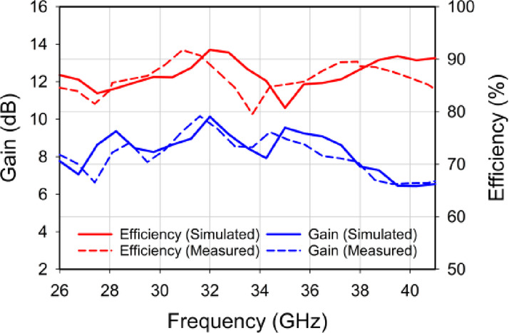
Gain and efficiency
It is mostly important to evaluate the antenna’s gain and efficiency when assessing antenna performance. A higher gain often indicates superior performance in terms of signal strength in the intended direction27. Antenna efficiency quantifies the degree to which an antenna efficiently transforms input power into emitted electromagnetic waves28,29. Figure 11 illustrates both the gain and efficiency of the proposed frequencies. The figure demonstrates that the designed antenna’s maximum gain is 10.14 dB and 9.5 dB throughout the bandwidth. As for the prototyped antenna, it has a gain of 10.1 and 9.3 dB. This indicates that the antenna efficiently converts input power into radio waves in a specific direction. The designed MIMO antenna demonstrated a radiation efficiency of 92% and 91% at the resonance frequency, and the prototyped antenna has a radiation efficiency of 91 and 89%, highlighting its capacity to transform input power into radiative energy efficiently.
Fig. 11.
The proposed MIMO antenna’s Simulated and measured gain and efficiency.
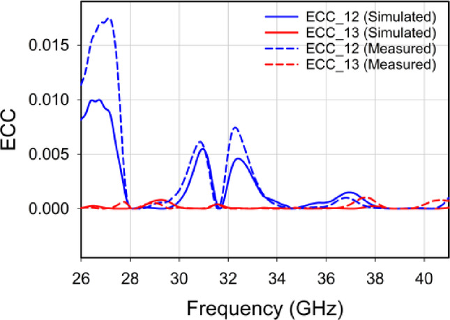
ECC
Comprehending and managing envelope correlation is crucial in designing and optimizing the MIMO antenna30. The ECC means Envelop Correlation Coefficient, which is employed to evaluate the degree of correlation with different antennas. Low-value ECC is preferred in multiple-input multiple-output (MIMO) systems. When antennas exhibit little or no correlation, the system can attain superior data rates, enhanced capacity, and heightened reliability31. The value of ECC for the proposed, simulated MIMO antenna is observed below 0.007 and measured below 0.017 at frequencies of 28 and 38 GHz, as depicted in Fig. 12.
 |
1 |
Fig. 12.
Proposed MIMO antenna’s simulated and measured ECC.
The diversity gain
Higher ECC is correlated with increased diversity gain. Diversity gain refers to enhancing the signal quality obtained by employing multiple antennas32. It aids in addressing problems such as signal degradation and enhances the dependability of wireless communication networks33,34. The performance outcome of the DG is depicted in Fig. 13. Within the dual bands, the DG is more than 9.96 dB for simulated and 9.91 for measured.
 |
2 |
Fig. 13.

Simulated and measured DG of proposed MIMO antenna.
CCL and TARC
Figure 13 shows the key performance metrics for the four-port MIMO antenna, designed to function at both 28/38 GHz frequencies. In Fig. 14 (a), the plot displays the (CCL) means Channel Capacity Loss, indicating the variation of CCL with frequency. For the MIMO antenna, CCL is an essential parameter as it measures the loss in channel capacity due to mutual coupling and correlation between antenna ports. The plot illustrates that our proposed antenna exhibits a relatively low CCL at 28 and 38 GHz, suggesting that the antenna effectively minimizes mutual coupling at these frequencies. This low CCL value is advantageous, indicating reduced interference between antenna elements and ultimately improving MIMO performance. The CCL can be computed using Eq. 335.
 |
3 |
Fig. 14.

Simulated and measured (a) CCL and (b) TARC of proposed MIMO antenna.
The two-port correlation matrix at the receiver can be computed using Eq. 4.
 |
4 |
where
 |
The coefficients for ports 1 and 2 are denoted as (x) and (y), respectively. The recommended CCL standard is less than 0.5 bps/Hz. A CCL below 0.4 bps/Hz is generally preferred. The proposed antenna consistently maintains a Channel Capacity Loss (CCL) of less than 0.15 bits per second per Hertz (bps/Hz) throughout the operational frequency range.
In Fig. 14 (b), the TARC plot provides valuable insights into the efficiency of the antenna system for transmitting and receiving signals. The TARC measurement is essential in understanding the signal reflected back to the source, with lower (more negative) values indicating superior performance. In our proposed design, the TARC demonstrates significant dips at 28 GHz and 38 GHz, signifying outstanding impedance matching and efficient signal transmission at these specific frequencies. Equation 5 can be utilised to ascertain this36.
 |
5 |
These characteristics suggest excellent isolation between the antenna elements and an overall high efficiency in signal handling. These findings align well with the simulated gain and efficiency values of 10.1 dB and 92% at 28 GHz, as well as 9.3 dB and 91% at 38 GHz.
Impedance
When analyzing the Microstrip Patch Antenna, the Z-matrix is a crucial element. The Z-matrix greatly assists in evaluating the impedance matching of the antenna. Impedance matching must be done correctly to transfer power between the transmission line and the antenna effectively37. Figure 15(i) and Fig. 15(ii) display the real and imaginary parts of the impedance matrix for frequencies of 28 GHz and 38 GHz, respectively. As illustrated in the figure, the real component of the impedance parameter at both frequencies is quite near 50 ohms. In contrast, the impedance parameter is relatively 0 when it comes close to the imaginary component.
Fig. 15.

Impedance at (i) 28 GHz and (ii) 38 GHz of proposed MIMO antenna.
Radiation pattern
A two-dimensional radiation pattern illustrates how an antenna radiates or receives electromagnetic waves. It indicates how the direction of the beam influences the power emitted. When detailing the radiation pattern along various axes, “XY,” “YZ,” and “ZX” denote the antenna’s alignment and the respective axes. The E-field radiation pattern represents the direction and intensity of the antenna’s electric field concerning the azimuthal angle (phi). Conversely, an antenna’s H-field radiation pattern outlines the variations in magnetic field strength and direction related to the polar angle38. Figure 16 displays the simulated and measured 2D radiation patterns at 28 GHz and 38 GHz frequencies, respectively. Operating at 28 GHz with an angular beam width of 22.7° at the 3 dB level, the E-field shows a primary lobe magnitude of 23.9 dBV/m at φ = 0°, with a half-power beam width of 25.9° and a lobe magnitude of 8.63 dBV/m at φ = 90° for both simulated and measured data at the first resonant frequency39. At the second operating frequency in the E-field, the primary lobe magnitude at φ = 0° is 19.1 dBV/m, while the 3 dB angular beam width at φ = 90° is 13.3° at 38 GHz. At this frequency, the 3 dB angular beam width is 14.4°, and the central lobe magnitude at φ = 0° is -30.6 dBA/m for simulated results, similar to measured results when analyzing the H-field.
Fig. 16.

Simulated and measured normalized radiation pattern of proposed MIMO antenna at 28 GHz and 38 GHz.
Proposed antenna’s current distribution (CD)
The anticipated surface current distribution of the MIMO antenna at 28 and 38 GHz is shown in Fig. 17, where one excited port and associated loads terminate at the other ports.
Fig. 17.

Current distribution of proposed MIMO Antenna at (i) 28 GHz, and (ii) 38 GHz.
Figure 17 shows that all the antennas display the absence of surface current, apart from Ant.1, is triggered by a surface current. No surface current is generated by the other antennas when Antenna 2 is turned on alone. The other configurations also show the same behaviour pattern when stimulated by Ant. 3 or Ant. 4. Decoupling also results in a limited surface current distribution, as seen in the previously mentioned cases.
RLC equivalent circuit analysis
The antenna’s equivalent circuit is determined using Agilent ADS software’s CST Studio simulation and circuit design tools for impedance analysis40. Figure 18 shows an RLC circuit, or lumped element model, comparable to the proposed MIMO antenna in terms of its characteristics. The resonance frequency at 28 GHz is caused by L1, C1, and R1, whereas L2, C2, and R2 cause the resonance frequency at 38 GHz. Lf1 and its capacitance by Cf1 represent the first feedline’s inductance. Lf2 is the feedline two inductance, and Cf2 is the capacitance. The three components that comprise feedline three are Lf3, Cf3, and Rf3. The two patches of an array element have a capacitance and an inductance that is mutually reflected (Lp-p and Cp-p, respectively). Each array antenna also has its inductance, which works both ways. L1-2 and C1-2, respectively, handle antenna 1 and 2’s inductance and capacitance. The capacitance between antennas 2 and 3 is C2-3, and the mutual inductance is L2-3. Antennas 3 and 4’s inductance and capacitance are denoted as L3-4 and C3-4, respectively. The capacitance and inductance between antennas 1 and 4 are denoted as C1-4 and L1-4, respectively. Antennas 2 and 4 have an inductance of L2-4 and a capacitance of C2-4, respectively. Antenna 2 and 4 have inductances of L2-4 and capacitances of C2-4, respectively. The inductances (L1, L2, Lf3, Lf1, Lf2L/Lf2R, Lp-p) are given as 1 pH, 40 pH, 0.01 pH, 0.1 pH, 1.4 nH, and 0.1 pH, respectively. The capacitances (C1, C2, Cf3, Cf1, Cf2L = Cf2R, Cp-p, C1-2/C2-3/C1-4, C1-3/C2-4) are specified as 13 pF, 0.71911 pF, 0.04553 pF, 0.1 pF, 38.245 pF, 0.060568 pF, 0.0528 pF, and 0.000528 pF, respectively. The resistances (R1, R2, Rf1) are listed as 50 Ohms, 57.24 Ohms, and 46.5 Ohms. Figure 19(a) and Fig. 19(b) compare the simulated Reflection and Transmission Coefficients of CST and ADS, respectively.
Fig. 18.

Equivalent circuit model of the suggested MIMO antenna.
Fig. 19.

(a) Simulated Reflection and (b) Transmission Coefficients in ADS and CST.
Machine learning (ML) analysis
Incorporating machine learning into antenna design can automate optimization and enhance antenna performance41. The efficacy of machine learning in antenna design hinges on the accuracy of the training data, the selection of features, and the suitability of the chosen machine learning model. There are two parts to the machine learning approach. Start by creating the 5G MIMO antenna using the simulation program CST. The parametric sweep dataset should then be obtained. Using machine learning model training on the provided dataset, identify the best approach42. We estimated the benefit using multiple regression machine learning after gathering 3264 data points. After using CST MWS to simulate the suggested antenna, this estimation was completed. 80% of the data will be used for training, while the remaining 20% data (652 data) will be kept for testing. The input variables in our dataset include the dimensions of the substrate, such as feed length, patch length, patch width, ground length, and ground width. The primary output is the gain parameter. Using the training dataset, we employ a regression machine-learning approach based on features and labels. After training is complete, the model can accurately predict gain based on input parameters. Figure 20 illustrates the sequential process of developing machine learning.
Fig. 20.
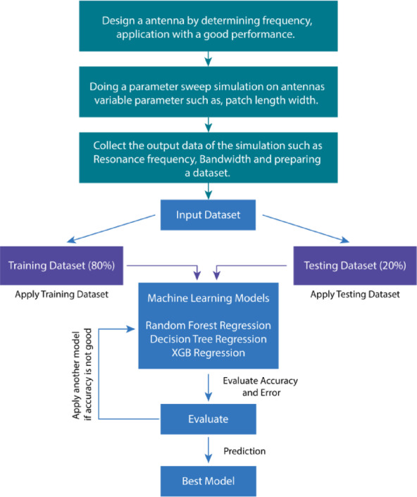
Schematic depicting the step-by-step procedure that goes into creating machine learning.
Decision tree regression
The decision tree regressor is trained using randomly produced data and subsequently employed to forecast the target value for a novel data point43. A machine learning approach, decision tree regression, can be applied to regression and classification tasks44. Decision trees are usually thought of when classification problems arise; however, by changing their prediction process, they can also be used for regression tasks.
XGB regression
XGBoost, short for Extreme Gradient Boosting, is a robust and efficient ML technique that excels at regression jobs. As an ensemble learning technique, it takes the forecasts of numerous weak learners (usually decision trees) and builds a robust model45.
Random forest regression
Random Forest Regression is a powerful ensemble learning technique commonly used for regression tasks. This approach involves training a multitude of decision trees and combining their individual predictions to arrive at a final output, which often results in improved accuracy and helps to mitigate overfitting issues46. By leveraging the collective knowledge of multiple trees, Random Forest Regression provides enhanced control and robustness in tackling regression challenges47.
Nonparametric regression
Nonparametric regression techniques are particularly advantageous for analyzing data that display intricate and nonlinear associations. Nevertheless, non-parametric approaches may necessitate more data than parametric methods, and selecting specific parameters might influence the outcomes48.
Linear regression
A statistical model known as linear regression seeks to establish a straight-line relationship between one or more parameters, known as predictor variables, and a response variable, also known as the dependent variable49.
Metrics for performance measurement
The accuracy with which a regression model predicts the values of a continuous outcome variable is assessed using performance evaluation measures. A model’s accuracy, precision, and overall performance can be evaluated using these indicators50. A popular way to measure how well a regression model works is to look at its (MAE) which is Mean Absolute Error. It calculates the average absolute variances among the observed numbers (actual) and the expected ones (predicted). The MAE is represented visually in Eq. 151.
 |
6 |
Where, number of errors is referred as “n”, and  used for error absolute
The MSE is the short form of Mean Squared Error, which is a widely used metric of a regression model which assesses the effectiveness. The mean of the squared variances between the projected and observed values is determined by the metric. The intended MSE formulation is presented in Eq. 252.
 |
7 |
As a standard performance measure, (RMSE) is the short form of Root Mean Squared Error, which assesses how well a regression model performs. The square root of the (MSE) measures the average magnitude of the errors between the observed (actual) values and predicted values53.
 |
8 |
The range of R square values is between 0 and 1. A score of 1 signifies an optimal match, wherein the model accounts for all the variability in the dependent variable54. A value of 0 specifies that none of the variability is taken into account by the model.
 |
9 |
Where


The term “Variance core” is generally not used or recognized in statistics and machine learning. Despite this, it might be advantageous to study other metrics if one can explain a concept related to variation55.
 |
10 |
Table 2 provides a comparison and overview of the predictive performance of five regression models, given a set of input values, concerning instruction. The accuracy of the methodologies was assessed by means of root mean squared error (RMSE), mean absolute error (MAE), and mean standard error (MSE). The outcomes of multiple models are juxtaposed adjacently in Figs. 21 and 22. The findings indicate that the Random Forest Regression model has minimal inaccuracies in MAE (15.13%), MSE (6.61%), and RMSE (25.72%). The Random Forest Regression model excels in variance score accuracy at 95.74% and an R-squared value of 95.66%. Figure 23 demonstrates that there is a negligible difference (very close to 0) between the gains that were actually observed and those that were predicted using Random Forest Regression.
Table 2.
The performance of the gain prediction.
| Algorithms | MAE | MSE | RMSE | R-Square | Var Score |
|---|---|---|---|---|---|
| Decision Tree Regression | 17.56% | 10.07% | 31.74% | 93.40% | 93.50% |
| XGB Regression | 27.92% | 19.73% | 44.42% | 87.05% | 87.08% |
| Gausian Process Regression | 65.06% | 96.97% | 98.47% | 36.37% | 36.40% |
| Random Forest Regression | 15.13% | 6.61% | 25.72% | 95.66% | 95.74% |
| Ridge Regression | 63.32% | 93.84% | 96.87% | 38.43% | 38.45% |
Fig. 21.

Error matrix bar graph for Random Forest Regression.
Fig. 22.

Accuracy comparative bar chart for Random Forest Regression.
Fig. 23.

Comparison of the predicted and simulated gains with Random Forest Regression.
Conclusions
This study presents an innovative T-shaped slotted four-element MIMO antenna system that incorporates a parasitic decoupling structure to improve performance at millimeter-wave frequencies of 28 GHz and 38 GHz, resulting in a compact design. The antenna functions proficiently in the 28 GHz and 38 GHz bands, markedly enhancing gain and efficiency. The gain is specifically 10.14 dB at 28 GHz and 9.5 dB at 38 GHz, based on simulated data. The maximum efficiency exceeds 90% at both 28 GHz and 38 GHz frequencies. Furthermore, the isolation yielded significant results, particularly with measurements at -34 and − 36 dB at 28 GHz and 38 GHz frequencies respectively. The RLC equivalent circuit model of the antenna created by ADS Agilent and the CST-simulated antenna design exhibit virtually comparable performance. Additionally, five distinct regression models have been employed to ascertain the antenna’s gain. To verify the predictions generated by the supervised regression algorithms, several performance metrics, including MAE, MSE, RMSE, R-squared, and variance scores, are calculated. These metrics are designated as “performance metrics.” Comprehensive analyses and obtained results indicate that random forest regression outperforms other regression machine learning models in prediction accuracy, evidenced by a mean squared error (MSE) of 15.13%, mean absolute error (MAE) of 6.61%, root mean squared error (RMSE) of 25.72%, R-squared value of 95.66%, and variance score of 95.74%. The findings from simulation and measurement are very congruent, and the MIMO antenna created for 5G applications is effective. The simulation, measurement, and expected outcomes validate the suggested MIMO antenna’s appropriateness for 5G applications.
Acknowledgements
“The authors extend their appreciation to the Deanship of Scientific Research and Libraries in Princess Nourah bint Abdulrahman University for funding this research work through the Research Group project, Grant No. (RG-1445-0058). Also, the authors would like to thank Prince Sultan University for their support.”
Author contributions
Conception, design, data collection, analysis, and simulation were initially carried out by M.A.H, R.A.A, M.S.A, and J.H.N. Funding: M.A. and A.A.A. All authors contributed to complete the writing and presentation of the whole manuscript.
Funding
“The authors extend their appreciation to the Deanship of Scientific Research and Libraries in Princess Nourah bint Abdulrahman University for funding this research work through the Research Group project, Grant No. (RG-1445-0058).”
Data availability
“The datasets generated and/or analyzed during the current study are available from thecorresponding author upon reasonable request.”
Declarations
Competing interests
The authors declare no competing interests.
Footnotes
Publisher’s note
Springer Nature remains neutral with regard to jurisdictional claims in published maps and institutional affiliations.
Contributor Information
May Almousa, Email: mmalmousa@pnu.edu.sa.
Abdelhamied A. Ateya, Email: aateya@psu.edu.sa
References
- 1.Sellak, L. et al. ANFIS-Based $$4\times 4$$ Dual Band Circular MIMO Antenna Design with Pretty-Small Size and Large Bandwidth for 5 G Millimeter-Wave Applications at 28/38 GHz. J. Infrared Millim. Terahertz Waves. 44(7–8), 551–601. 10.1007/s10762-023-00924-3 (2023).
- 2.Khedkar, A., Musale, S., Padalkar, G., Suryawanshi, R. & Sahare, S. An Overview of 5G and 6G Networks from the Perspective of AI Applications. J. Inst. Eng. India Ser. B104(6), 1329–1341. 10.1007/s40031-023-00928-6 (2023).
- 3.Zahid, M., Taqdeer, M. M. & Amin, Y. Sep., A Compact Dual-Band microstrip patch antenna for C- and X- and Ku-Band applications, in IEEC 2023, MDPI, 16. 10.3390/engproc2023046016 (2023).
- 4.Ehrhart, I. C. et al. Coronary vascular and myocardial responses to carotid body stimulation in the dog, Am. J. Physiol.229(3), 754–760. 10.1152/ajplegacy.1975.229.3.754 (1975). [DOI] [PubMed]
- 5.Rai, J. K., Yadav, S., Ranjan, P., Chowdhury, R. & Das, G. A compact quad element MIMO CPW fed ultra-wideband antenna for future wireless communication using machine learning optimization. Int. J. Commun. Syst.38(3), e5995. 10.1002/dac.5995 (2025).
- 6.Haque, Md A. et al. High-bandwidth millimetre wave multiple-input multiple-output antenna for 38 GHz 5G mobile applications, TELKOMNIKA Telecommun. Comput. Electron. Control. 23(2), 283. 10.12928/telkomnika.v23i2.26491 (2025).
- 7.Sorathiya, V., Alharbi, A. G. & Lavadiya, S. Design and investigation of unique shaped low-Profile material-based superlative two-element printed ultrawideband MIMO antenna for Zigbee/WiFi/5G/WiMAX applications, Alex. Eng. J.. 64, 813–831. 10.1016/j.aej.2022.10.051 (2023).
- 8.Jain, R., Thakare, V. V. & Singhal, P. K. Design and Comparative Analysis of THz Antenna through Machine Learning for 6G Connectivity, IEEE Lat. Am. Trans.22(2), 82–91. 10.1109/TLA.2024.10412032 (2024).
- 9.Rai, J. K., Ranjan, P., Chowdhury, R. & Jamaluddin, M. H. Design and Optimization of Dual Port Dielectric Resonator Based Frequency Tunable MIMO Antenna with Machine Learning Approach for 5G New Radio Application, Int. J. Commun. Syst.37(13), e5856. 10.1002/dac.5856 (2024).
- 10.Jain, R., Singhal, P. K. & Thakare, V. V. An Effective Approach for Optimizing Antenna Design Based on Machine Learning Models, in Artificial Intelligence and Sustainable Computing, M. Pandit, M. K. Gaur, and S. Kumar, Eds., in Algorithms for Intelligent Systems., Singapore: Springer Nature Singapore, pp. 309–320. (2023). 10.1007/978-981-99-1431-9_24
- 11.Rai, J. K., Ranjan, P. & Chowdhury, R. Dual-Band high tuning range frequency reconfigurable cylindrical dielectric resonator antenna for n7, n30, n38, n40, n41, n46, n47, n53 and n79 5G new radio application with machine learning approach. Arab. J. Sci. Eng.10.1007/s13369-024-09684-1 (2024).
- 12.Raheel, K. et al. E-Shaped H-Slotted dual band MmWave antenna for 5G technology. Electronics10(9), 1019. 10.3390/electronics10091019 (2021).
- 13.Rafique, U. et al. Prog Electromagn. Res. C112, 83–98. 10.2528/PIERC21021302 (2021). [Google Scholar]
- 14.Hasan, M. N., Bashir, S. & Chu, S. Dual band omnidirectional millimeter wave antenna for 5G communications, J. Electromagn. Waves Appl.33(12) 1581–1590. 10.1080/09205071.2019.1617790 (2019).
- 15.Marzouk, H. M., Ahmed, M. I. & Shaalan, A. E. H. Novel dual-band 28/38 GHz mimo antennas for 5g mobile applications. Prog Electromagn. Res. C. 93, 103–117. 10.2528/PIERC19032303 (2019). [Google Scholar]
- 16.Farahat, A. E. & Hussein, K. F. A. Dual-Band (28/38 GHz) wideband MIMO antenna for 5G mobile applications. IEEE Access.10, 32213–32223. 10.1109/ACCESS.2022.3160724 (2022). [Google Scholar]
- 17.Tadesse, A. D., Acharya, O. P. & Sahu, S. A Compact Planar Four-port MIMO Antenna for 28/38 GHz Millimeter-wave 5G Applications, Adv. Electromagn.. 11 (3), 16–25. 10.7716/aem.v11i3.1947 (2022).
- 18.Kumar, A., Mahto, S. K., Sinha, R. & Choubey, A. Dual circular slot ring triple-band MIMO antenna for 5G applications, Frequenz75(3–4), (91–100). 10.1515/freq-2020-0138 (2021).
- 19.Dwivedi, A. K. et al. Circularly polarized printed dual Port MIMO antenna with polarization diversity optimized by machine learning approach for 5G NR n77/n78 frequency band applications. Sci. Rep.13(1), 13994. 10.1038/s41598-023-41302-2 (2023). [DOI] [PMC free article] [PubMed]
- 20.Rai, J. K. et al. Machine learning-enabled two‐port wideband MIMO hybrid rectangular dielectric resonator antenna for n261 5G NR millimeter wave, Int. J. Commun. Syst.37(16), e5898. 10.1002/dac.5898 (2024).
- 21.Khan, D., Ahmad, A. & Choi, D. Y. Dual-band 5G MIMO antenna with enhanced coupling reduction using metamaterials. Sci. Rep.14(1), 96. 10.1038/s41598-023-50446-0 (2024). [DOI] [PMC free article] [PubMed]
- 22.Tiwari, P., Kumar Rai, J., Gahlaut, V. & Ranjan, P. Compact quad element dual band high gain MIMO rectangular dielectric resonators antenna for 5G millimeter wave application. AEU - Int. J. Electron. Commun.178, 155280. 10.1016/j.aeue.2024.155280 (2024).
- 23.Rahaman, I. et al. Performance Investigation of Linearly Arranged Circular, Circular Planer, Rectangular, and Concentric Circular Antenna Arrays Using Robust NVL Techniques, Appl. Sci.. 12(22), 11481. 10.3390/app122211481 (2022).
- 24.Sharawi, M. S., Numan, A. B. & Aloi, D. N. Isolation improvement in a dual-band dual-element Mimo antenna system using capacitively loaded loops. Prog Electromagn. Res.134, 247–266. 10.2528/PIER12090610 (2013). [Google Scholar]
- 25.Biswas, A. K., Biswas, S., Haldar, S. & Nandi, A. A highly decoupled flexible 4-element MIMO antenna with band Notched characteristics for ultra wide-band wearable applications. AEU - Int. J. Electron. Commun.173, 154985. 10.1016/j.aeue.2023.154985 (2024).
- 26.Paul, L. C. et al. Design and Performance Exploration of a DGS Metamaterial MPA by Etching Four Dual Isosceles Triangular Defects on the Ground Plane, in International Conference on Computer, Communication, Chemical, Material and Electronic Engineering (IC4ME2), Rajshahi: IEEE, Feb. 2018, pp. 1–4., Rajshahi: IEEE, Feb. 2018, pp. 1–4. (2018). 10.1109/IC4ME2.2018.8465670
- 27.Rai, J. K. et al. High-Gain Triple‐Band T‐Shaped Dielectric Resonator Based Hybrid Two‐Element MIMO Antenna for 5G New Radio, Wi‐Fi 6, V2X, and C‐Band Applications With a Machine Learning Approach. Int. J. Commun. Syst.. 38(5), e6038. 10.1002/dac.6038 (2025).
- 28.Rai, J. K., Patel, U., Tiwari, P., Ranjan, P. & Chowdhury, R. Machine learning enabled compact Frequency-Tunable Triple‐Band Hexagonal‐Shaped graphene antenna for THz communication. Int. J. Commun. Syst.38(1), e6044. 10.1002/dac.6044 (2025).
- 29.Hossain Nirob, J. et al. Optimized tri-band MIMO antenna design for 6G terahertz applications and future connectivity, TELKOMNIKA Telecommun. Comput. Electron. Control. 23(2), 553. 10.12928/telkomnika.v23i2.26579 (2025).
- 30.Haque, M. A. et al. Performance improvement of THz MIMO antenna with graphene and prediction bandwidth through machine learning analysis for 6G application. Results Eng.p. 10321610.1016/j.rineng.2024.103216 (2024).
- 31.Ahmed, Md K. et al. Graphene-based THz antenna with a wide bandwidth for future 6G short-range communication. TELKOMNIKA Telecommun. Comput. Electron. Control. 23(2), 306. 10.12928/telkomnika.v23i2.26562 (2025).
- 32.Al-Bawri, S. S. et al. Machine learning technique based highly efficient slotted 4-port MIMO antenna using decoupling structure for sub-THz and THz 6G band applications. Opt. Quantum Electron.56(10), 1611. 10.1007/s11082-024-07249-y (2024).
- 33.Munir, M. E. et al. A Four Element mm-Wave MIMO Antenna System with Wide-Band and High Isolation Characteristics for 5G Applications, Micromachines14(4), 776. 10.3390/mi14040776 (2023). [DOI] [PMC free article] [PubMed]
- 34.Hossain Nirob, J. et al. Dual-band MIMO antenna for wideband THz communication in future 6G applications, TELKOMNIKA Telecommun. Comput. Electron. Control. 23(2), 295. 10.12928/telkomnika.v23i2.26553 (2025).
- 35.Urimubenshi, F., Konditi, D. B. O., De Dieu Iyakaremye, J., Moukala Mpele, P. & Munyaneza, A. A novel approach for low mutual coupling and ultra-compact Two Port MIMO antenna development for UWB wireless application, Heliyon. 8(3), p. e09057. 10.1016/j.heliyon.2022.e09057 (2022). [DOI] [PMC free article] [PubMed]
- 36.Rahman, M. A., Al-Bawri, S. S., Abdulkawi, W. M., Aljaloud, K. & Islam, M. T. A unique SWB multi-slotted four-port highly isolated MIMO antenna loaded with metasurface for IOT applications-based machine learning verification. Eng. Sci. Technol. Int. J.50, 101616. 10.1016/j.jestch.2024.101616 (2024).
- 37.Wang, T. et al. Deep Understanding of impedance matching and quarter wavelength theory in electromagnetic wave absorption. J. Colloid Interface Sci.595, 1–5. 10.1016/j.jcis.2021.03.132 (2021). [DOI] [PubMed]
- 38.Zhao, S., Wang, Z. & Dong, Y. A Planar Pattern-Reconfigurable Antenna With Stable Radiation Performance, IEEE Antennas Wirel. Propag. Lett.21(4), 784–788. 10.1109/LAWP.2022.3146599 (2022).
- 39.Niu, W., Sun, B., Zhou, G. & Lan, Z. Dual-Band Aperture Shared Antenna Array With Decreased Radiation Pattern Distortion. IEEE Trans. Antennas Propag.70(7), 6048–6053. 10.1109/TAP.2022.3161267 (2022).
- 40.Haque, M. A. et al. Machine learning-based novel-shaped THz MIMO antenna with a slotted ground plane for future 6G applications. Sci. Rep.14(1), 32162. 10.1038/s41598-024-79332-z (2024). [DOI] [PMC free article] [PubMed]
- 41.Jain, R., Vikas Thakare, V. & Singhal, P. K. Enhancing circular microstrip patch antenna performance using machine learning models. Facta Univ. - Ser. Electron. Energ.36(4), 589–600. 10.2298/FUEE2304589J (2023). [Google Scholar]
- 42.Jain, R., Thakare, V. V. & Singhal, P. K. Employing machine learning models to predict return loss precisely in 5G antenna. Prog Electromagn. Res. M. 118, 151–161. 10.2528/PIERM23062505 (2023). [Google Scholar]
- 43.Jain, R., Thakare, V. V. & Singhal, P. K. Revolutionizing Antenna Design: Machine Learning Innovations and Future Trajectories, in Advances in Chemical and Materials Engineering, K. Kavitha, T. Sabapathy, and V. Rajeshkumar, Eds., IGI Global, pp. 78–101. (2024). 10.4018/979-8-3693-2659-6.ch005
- 44.Kumar Rai, J., Ranjan, P. & Chowdhury, R. Machine Learning Enabled Al2 O3 Ceramic Based Dual Band Frequency Reconfigurable Dielectric Antenna for Wireless Application, IEEE Trans. Dielectr. Electr. Insul.31(5), 2840–2849. 10.1109/TDEI.2024.3395236 (2024).
- 45.Tajuddeen, I., Sajjadian, S. M. & Jafari, M. Regression models for predicting the global warming potential of thermal insulation materials. Buildings13(1), 171. 10.3390/buildings13010171 (2023).
- 46.Jain, R., Ranjan, P., Singhal, P. K. & Thakare, V. V. Estimation of S11 Values of Patch Antenna Using Various Machine Learning Models, in IEEE Conference on Interdisciplinary Approaches in Technology and Management for Social Innovation (IATMSI), Gwalior, India: IEEE, Dec. 2022, pp. 1–4., Gwalior, India: IEEE, Dec. 2022, pp. 1–4. (2022). 10.1109/IATMSI56455.2022.10119256
- 47.Haque, M. A. et al. Machine learning-based technique for directivity prediction of a compact and highly efficient 4-Port MIMO antenna for 5G millimeter wave applications. Results Eng.p. 10310610.1016/j.rineng.2024.103106 (2024).
- 48.Armstrong, T. B. & Kolesár, M. Simple and honest confidence intervals in nonparametric regression. Quant. Econ.11(1), 1–39. 10.3982/QE1199 (2020). [Google Scholar]
- 49.Özkaya, U., Yiğit, E., Seyfi, L., Öztürk, Ş. & Singh, D. Comparative Regression Analysis for Estimating Resonant Frequency of C-Like Patch Antennas, Math. Probl. Eng., vol. pp. 1–8, Feb. 2021, 10.1155/2021/6903925 (2021).
- 50.Haque, M. A. et al. Regression supervised model techniques THz MIMO antenna for 6G wireless communication and IoT application with isolation prediction. Results Eng.p. 10350710.1016/j.rineng.2024.103507 (2024).
- 51.Nahin, K. H. et al. Performance prediction and optimization of a high-efficiency tessellated diamond fractal MIMO antenna for Terahertz 6G communication using machine learning approaches. Sci. Rep.15(1), 4215. 10.1038/s41598-025-88174-2 (2025). [DOI] [PMC free article] [PubMed]
- 52.Guo, Q. et al. Enhanced monthly streamflow prediction using an input–output bi-decomposition data driven model considering meteorological and climate information, Stoch. Environ. Res. Risk Assess., 38(8), 3059–3077. 10.1007/s00477-024-02731-1 (2024).
- 53.Md, A. et al. Machine learning-based technique for gain prediction of mm-wave miniaturized 5G MIMO slotted antenna array with high isolation characteristics. Sci. Rep.15(1), 276. 10.1038/s41598-024-84182-w (2025). [DOI] [PMC free article] [PubMed]
- 54.Haque, M. A. et al. Machine learning based compact MIMO antenna array for 38 ghz millimeter wave application with robust isolation and high efficiency performance. Results Eng.p. 10400610.1016/j.rineng.2025.104006 (2025).
- 55.Haque, M. A. et al. Multiband THz MIMO antenna with regression machine learning techniques for isolation prediction in IoT applications. Sci. Rep.15(1), 7701. 10.1038/s41598-025-89962-6 (2025). [DOI] [PMC free article] [PubMed]
Associated Data
This section collects any data citations, data availability statements, or supplementary materials included in this article.
Data Availability Statement
“The datasets generated and/or analyzed during the current study are available from thecorresponding author upon reasonable request.”