

Abstract
Transcranial magnetic stimulation (TMS) is a noninvasive procedure that uses magnetic fields to stimulate neurons in the brain and has been widely applied in the field of clinical neuromodulation. However, traditional TMS has limitations in terms of focality and stimulation depth, making it unable to achieve precise modulation of deep brain regions. As the stimulation depth increases, the focal area expands, potentially stimulating nontarget regions and causing negative side effects. Moreover, strongly induced electric fields can lead to adverse effects such as seizures. Temporal interference transcranial magnetic stimulation (TI-TMS) is a novel noninvasive neuromodulation technique that has considerable potential for reducing the focal area and increasing the stimulation depth. To study the mechanisms and effects of TI-TMS, this research first established a TI-TMS simulation platform based on a five-layer spherical model. This paper designed a double curved-elliptical coil structure, increasing the stimulation depth of the TI-TMS to 5.02 cm while reducing the focal area to 18.61 cm2. Finally, a TI-TMS system was developed, with a focus on the design and development of the insulated-gate bipolar transistor (IGBT) driving circuit and the coil capacitor resonance part. The current amplitude and frequency in the coils were measured to validate the system’s effectiveness. This study confirmed that TI-TMS can effectively stimulate deep brain regions and provide new insights for the application of TMS in the rehabilitation of neurological diseases.
Keywords: Transcranial magnetic stimulation, Temporal interference, Double curved-elliptical coils, Temporal interference transcranial magnetic stimulation system
Subject terms: Biomedical engineering, Electrical and electronic engineering
Introduction
Transcranial magnetic stimulation (TMS) is a noninvasive neuromodulatory tool that has achieved notable success in the study of brain functions and the rehabilitation of severe depressive disorders1, Parkinson’s disease2, and other neurological disorders3. The traditional TMS technique involves applying large pulse currents to the coil via a magnetic field generator to create a variable magnetic field4. It then induces an electric field inside the conductive brain tissues. The electric field generated by TMS can penetrate up to 1–2 cm into the brain. This depth is generally sufficient to reach cortical areas5.
However, traditional TMS technology faces a trade-off between stimulation depth and focality6. Although large coils can achieve deeper brain stimulation, their extensive focal areas cannot precisely target specific deep brain regions. Conversely, smaller coils offer better focus but are limited to shallow cortical areas7. As the magnetic field strength increases, so does the stimulation intensity on the superficial tissues of the head, potentially exceeding the safety guidelines of TMS and causing considerable harm to the human body8. In 2017, Grossman et al. proposed that the low-pass filtering property of the neural membrane may be leveraged to provide noninvasive stimulation of deep brain regions9. By applying high-frequency currents with a certain frequency difference to two pairs of electrodes placed on both sides of the brain, a low-frequency envelope modulation signal can be generated in deep brain regions to stimulate the neurons in that area. This approach was termed temporal interference transcranial alternating current stimulation (TI-tACS).
In TI-tACS, electrodes are placed above the scalp to convey electric current into the brain tissue, penetrating the skull. This approach raises concerns that the skin–electrode impedance could deteriorate the performance of electric current propagation10. Consequently, the applied current or voltage might oscillate when a constant value is maintained. Additionally, the asymmetrical geometries of the brain, as well as the tissue impedance distribution, potentially decrease the focality of the electric field generated in the target regions. Conversely, TMS can maintain constant voltage and current in the coils, thus bypassing the conductivity properties of the subject’s tissue. This ability exists mainly because the relatively high electrical impedance of biological tissue cannot distort magnetic stimulation-induced magnetic fields11.
Owing to these characteristics, combining the principles of temporal interference (TI) with TMS could be a practical approach for achieving noninvasive and focal deep-brain stimulation. In 2020, Majid Memarian Sorkhabi et al. conducted a simulation analysis on the low-frequency envelope induction electric field of temporal interference transcranial magnetic stimulation (TI-TMS)12. Compared with traditional TMS, magnetic stimulation combined with temporal interference has greater stimulation depth and a more focused region with a smaller area. In 2023, Adam Khalifa et al. designed and optimised a custom solenoid capable of generating temporally interfering induced electric fields to stimulate the rodent brain and express neurons for tracing through the C-Fos activation situation13. The results revealed no C-Fos expression in the region affected by only one high-frequency magnetic field, indicating that the recruitment of neural activity in the nontarget region was ineffective. In contrast, the area subjected to the superimposed low-frequency envelope-induced field presented more robust C-Fos expression, indicating that TI-TMS could activate neuronal action potentials. In summary, current research on TI-TMS remains limited primarily to simulation analyses and preliminary animal experiments. Majid Memarian Sorkhabi et al. initially proposed the concept of the TI-TMS, yet their work focused exclusively on finite-element simulations using two circular coils \* MERGEFORMAT12. Subsequently, Adam Khalifa et al. conducted animal experiments utilizing a signal generator, and demonstrated that TI-TMS can effectively stimulate the rodent brain13. However, comprehensive experimental validations, particularly those involving sophisticated coil designs and detailed TI-TMS systems, remain scarce. Accordingly, this study further explored the advantages of TI-TMS in terms of stimulation depth and focality by designing the double curved-elliptical coils. Furthermore, in this study, a safe and stable TI-TMS system was designed, and safety and stability tests were conducted, establishing a foundation for future biological experiments.
The remainder of this paper is organised as follows. In Section “Finite element analysis”, a five-layer spherical model is established to substitute for the real head model. The performance of TI-TMS and TMS was compared through variations in the size and position of the two circular coils. Then, double curved-elliptical coils are designed to demonstrate the advantages of TI-TMS. With the optimal coil angle, the stimulation depth can reach 5.02 cm, with a focal area of 18.61 cm2. In Section “Design of the temporal interference magnetic stimulation system”, the overall structure of the TI-TMS system is introduced, and measurements of the current amplitude and frequency within the coil are conducted to validate the system’s effectiveness. TI-TMS provides new insights into the future application of TMS in the rehabilitation of neurological disorders. Additionally, the TI-TMS system designed in this study lays a foundation for future experiments.
Finite element analysis
As shown in Fig. 1, the sinusoidal currents  and
and  (with high-frequency f1 and f2) are passed into two circular coils, generating two high-frequency magnetic fields, which in turn generate two high-frequency oscillating electric fields inside the brain. Like in TI-tACS, neurons cannot be effectively activated by high-frequency electric fields. Consequently, neurons in the regions of the cerebral cortex affected by each coil individually cannot be activated. However, in the region where the two coils act simultaneously, the induced electric fields superimpose, generating a low-frequency envelope-induced electric field, which can stimulate neurons in that area14.
Fig. 1.
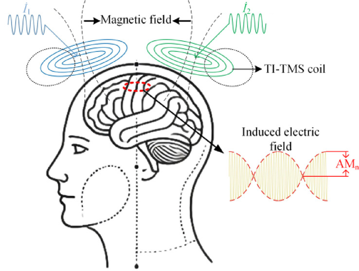
Schematic of the temporal interference magnetic stimulation principle.
The amplitude modulation intensity of n (AMn) is defined to quantify the stimulation intensity of the induced electric field in TI-TMS, which represents the envelope modulation amplitude of the electric field at position n15. AMn is quantified as
| 1 |
where  and
and  represent the induced electric fields generated by the two coils at position n, respectively.
According to existing research, neurons are more easily activated when the electric field direction is parallel to the neuronal axis16. For different brain regions, the neuronal axon orientations vary. During actual stimulation, the coil positions must be adjusted according to the different neuronal axon directions to achieve precise and effective stimulation. In this study, two coils are placed symmetrically on both sides of the x-axis, generating an induced electric field with a maximum component along the y-axis direction. Additionally, the three directions used in this study are chosen to facilitate the calculation of specific induced electric field values. If adjustment of the induced electric field direction is required for different brain regions, this adjustment can be accomplished by modifying the coil positions. Consequently, the analysis is confined to the y-component of the induced electric field at point n, leading to the following revised formula:
| 2 |
where  and
and  represent the y-components of the induced electric fields generated by the two coils at position n, respectively.
Calculation of stimulation depth and focality
To quantitatively evaluate the performance of TMS and TI-TMS, three crucial characteristics of magnetic stimulation are calculated on the basis of the simulation results: stimulation intensity, stimulation depth and focality17.
In traditional TMS, the stimulation intensity Emax (V/m) refers to the maximum induced electric field produced by the coil at the cortical surface. For the TI-TMS, Emax is determined by the amplitude of AMny. The stimulation depth is quantified by the half-value depth d1/2(cm), which is defined as the radial distance from the cortical surface to the deepest point where Emax is half of its maximum value on the cortical surface. The focal S1/2 (cm2) of TMS typically denotes the area within which the induced electric field is sufficiently strong to effectively stimulate neurons, reflecting the coil’s capacity to concentrate the electric field in the intended target region18. S1/2 is defined as
 |
3 |
where V1/2(cm3) is the half-value volume—the volume of the brain region exposed to an electric field amplitude modulation intensity as strong as or stronger than half of the maximum electric field amplitude modulation intensity.
Simulation model construction
The electromagnetic field module of COMSOL is used for finite element analysis. The real head model is evaluated by a five-layer sphere model with a radius of 92 mm in this study. The five-layer sphere model structure consists of the scalp, skull, cerebrospinal fluid (CSF), grey matter, and white matter. The measurements for the grey matter, scalp, skull, and CSF were 4.9 mm, 7.4 mm, 2.5 mm, and 7.2 mm, respectively. A 70 mm-radius sphere includes the brain’s most profound white matter19. The electrical properties of the human tissue used in this work are provided by the online IFAC database in the United States20.
To facilitate the analysis of the impact of different coil structures on the simulation results, this study first employs two circular coils for finite element analysis. By varying the angle between these coils, the effects of different coil structures on the stimulation performance of TMS and TI-TMS are examined. To perform a preliminary analysis of various coil geometries, this study proposes the use of double curved-elliptical coils for TI-TMS, which are designed to better conform to the scalp anatomy. The proposed design of the five-layer sphere model and the double curved-elliptical coils is illustrated in Fig. 2. In Fig. 2, β represents the angle between the two coils. A and a denote the inner and outer diameters of the short axis of the curved elliptical coils, respectively. B and b represent the inner and outer diameters of the long axis of the curved elliptical coils, respectively.
Fig. 2.

Proposed design of the five-layer sphere model and the coil position.
Simulation results of the two circular coils
In the finite element simulations, the high-frequency currents applied to the two circular coils have an amplitude of 100 A. For the TMS, the frequency of both coils is set to 5.00 kHz, and for the TI-TMS, the frequencies of the two coils are set to 5.00 kHz and 5.02 kHz. For the frequency selection, the fundamental frequency of 5.0 kHz is chosen because, as demonstrated by Fang Xiao, et al.21, it can generate a higher magnetic field strength while still effectively stimulating neurons. For the selection of the frequency difference in the TI-TMS, frequency differences within 100 Hz have little impact on the stimulation effect. Therefore, the commonly used 20 Hz frequency difference is chosen for the simulation.
The simulation results of the TMS and TI-TMS with different coil angles of the two circular coils are shown in Fig. 3. A comparison of the simulation results for the same coil angles reveals that the Emax of the TI-TMS is much smaller than that of the TMS, but the S1/2 of the TI-TMS is smaller than that of the TMS. A comparison of the simulation results for different coil angles reveals that changes in the coil angle affect S1/2. For the TMS, S1-2 considerably increases and spreads to both ends as the coil angle decreases. For the TI-TMS, S1/2 also increases with decreasing coil angle, but the rate of increase is lower than that in the TMS simulation.
Fig. 3.

Simulation results of the TI-TMS and TMS with different coil angles of two circular coils: (a) simulation model of different angles, (b) simulation results of the TI-TMS, (c) simulation results of the TMS.
Furthermore, COMSOL’s built-in calculation tools are used to analyse the differences in S1/2 and d1/2 between the TMS and TI-TMS at different coil angles. d1/2 for TMS and TI-TMS at different is plotted against the coil angle in Fig. 4a. An analysis of the variation in d1/2 with the coil angles reveals that the stimulation depth of the TMS is always lower than that of the TI-TMS. As the coil angle decreases, the stimulation depth of the TI-TMS increases, indicating that reducing the angle between the two coils increases the stimulation depth. S1/2 for TMS and TI-TMS is plotted against the coil angle in Fig. 4b. An analysis of the variation in S1/2 with the coil angles reveals that the focal area of the TMS is considerably larger than that of the TI-TMS. As the coil angle increases, the focal area of the TI-TMS also increases. Therefore, the coil structure must be optimised to further reduce the focal area.
Fig. 4.

Variation trends of d1/2 and S1/2: (a) variation trends of d1/2 under different coil angles, (b) variation trends of S1/2 under different coil angles.
Simulation results of double curved-elliptical coils
To increase the stimulation depth while maintaining the focal area at a relatively appropriate size, a double curved-elliptical coil structure, which fits more closely to the scalp, is designed. This design allows the coils to conform to the scalp while S1/2 and d1/2 are optimised. The simulation results of the TI-TMS with double curved-elliptical coils are shown in Fig. 5a, b. The simulation results indicate that the stimulation intensity of the five-layer spherical model is 28 V/m. The red sections in Fig. 5c, d represent the processed V1/2 and d1/2, respectively. V1/2 and d1/2 in the X–Z plane demonstrate a good focality along with a substantial stimulation depth. In practical applications, this approach can effectively stimulate deep brain regions.
Fig. 5.
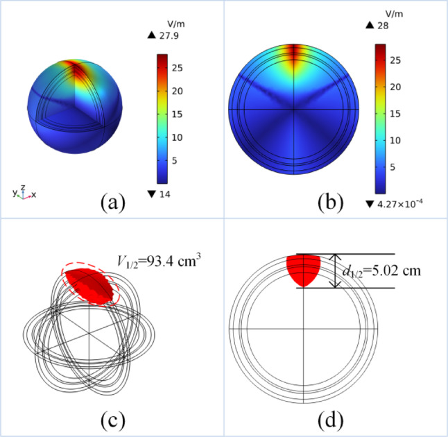
Simulation results of double curved-elliptical coils: (a) simulation results in 3D, (b) simulation results of the X–Z plane, (c) simulation results of V1/2, (d) simulation results of d1/2.
Simulations were conducted to evaluate the performance differences between double curved-elliptical coils with TI-TMS and other coil structures featuring TMS and TI-TMS, including several commercially available products. The corresponding evaluation index values for different coil structures are presented in Table 1. These coils include circular coil, figure-of-8 coils, double-cone coils, and other coil structures for deep brain stimulation18. As shown in Table 1, for TMS, figure-of-8 coils offer better focus but are limited to stimulating shallow cortical areas. The deep brain stimulation coil structures achieve deeper brain stimulation, but their extensive focal areas cannot precisely target specific deep brain regions. However, when the TI-TMS method is used, two 70 mm circular coils increase the stimulation depth with a degree of focus. The four-coil configuration designed by Zonghao Xin et al. reduces the focality with a stimulation depth of 2.2 cm14. Under the double curved-elliptical coils of this study, d1/2 increases to 5.02 cm, and S1/2 is controlled at 18.61 cm2. Therefore, the design of double curved-elliptical coils with the TI-TMS method can solve the trade-off between stimulation depth and focality to a certain extent.
Table 1.
Performance of different coil structures.
| Coil structures | d1/2 (cm) | S1/2 (cm2) | |
|---|---|---|---|
| TMS | Magstim 50 mm circular coil | 1.4 | 52 |
| Magstim 70 mm figure-of-8 coil | 1.4 | 15 | |
| Magstim double cone coil | 1.95 | 34 | |
| Brainsway H2 coil | 2.35 | 90 | |
| Crown coil | 2.62 | 160 | |
| Flux ball coil | 3.5 | 300 | |
| TI-TMS | Two 70 mm circular coils | 2.3 | 17 |
| Four-coil configuration | 2.2 | 11 | |
| Double curved elliptical coils | 5.02 | 18.61 |
In addition, to analyse the stimulation performance of the TI-TMS in the asymmetric head model structure, a three-dimensional MRI-derived head model is utilised. The real head model comprises four layers: the scalp, skull, cerebrospinal fluid, and grey matter. Figure 6a shows a schematic of the relative position of the double curved-elliptical coil structure with respect to the real head model. Figure 6b shows the simulation results of the entire head model in the X–Z plane. In addition, Fig. 6c presents the simulation results for the grey matter layer in the X–Z plane. The simulation results indicate that, in the real head model, the TI-TMS can still maintain good focus and that the asymmetry of the head structure does not affect the simulation results.
Fig. 6.

Simulation results of double curved-elliptical coils with real head model: (a) the relative position of the double curved-elliptical coils structure with respect to the real head model, (b) simulation results of the entire head model in the X–Z plane, (c) simulation results for the gray matter layer in the X–Z plane.
Design of the temporal interference magnetic stimulation system
The feasibility and advantages of the TI-TMS over traditional TMS are validated through comprehensive modeling and simulation analyses. However, there is a lack of physical experimental verification of the TI-TMS mode, so the design and construction of the TI-TMS system that can output stable frequency sinusoidal current is a prerequisite for the experimental verification of TI-TMS.
The overall structure of the system
The overall diagram of the designed TI-TMS system is shown in Fig. 7. The primary function of this system is to convert the main power to the high-frequency sinusoidal current required for the TI-TMS in three distinct stages. In the first stage, the DC power converts the AC voltage to the DC voltage, and the amplitude of the DC voltage can be adjusted. The second stage converts the DC voltage into two fixed-frequency AC square-wave voltages through two full-bridge circuits. Two different frequencies of pulse width modulation (PWM) signals are generated through the TMS320F28335 digital signal processor (DSP) as the core control chip. The PWM signals that can drive the insulated-gate bipolar transistor (IGBT) of the H-bridge inverter are then generated by the driver module, and two kinds of drive pulses of different frequencies are used to control the IGBTs of H-Bridge Inverter Ι and H-Bridge Inverter II. In the third stage, the AC square-wave voltage oscillates in the LC resonant circuit, generating a high-frequency sinusoidal current in the stimulation coils.
Fig. 7.

The overall diagram of the TI-TMS system.
Circuit design details of the system
The detailed schematic of the implemented TI-TMS system is shown in Fig. 8. The circuit includes two full-bridge inverter circuits, each comprising four IGBTs. In the primary circuit, Cs1 and Cs2 are resonant capacitors, Ls1 and Ls2 are the inductance values of the two stimulation coils, and Rs1 and Rs2 are the total resistances of the two circuits.
Fig. 8.

Detailed schematic of the TI-TMS system.
The operating principle of the circuit is as follows. By controlling the signals to switch the diagonally opposite bridge arms of the full-bridge inverter circuit simultaneously, with each pair alternately conducting for 180°, fixed-frequency rectangular wave voltages U1 and U2 are obtained in the primary circuit. Expanding the rectangular wave U1 with amplitude u1 into Fourier series to get yields
| 4 |
where ω = 2πf.
According to Eq. (4), the square wave voltage is a combination of a sinusoidal fundamental voltage with frequency f and other higher harmonics. To obtain a sinusoidal current with the same fundamental frequency on the stimulation coil, a series capacitor needs to be added to filter out harmonics higher than the third order. On the basis of the inductance‒capacitance resonance formula shown in Eq. (5), the required value of the series resonance capacitor can be calculated.
 |
5 |
A physical image of the full-bridge inverter module is shown in Fig. 9. The IGBT transistor used in this system is the FGH60N60SMD model, with a voltage rating of VCES = 600 V and a DC collector current (IC) tolerance of 120 A at TC = 20 °C and 60 A at TC = 100 °C. Two IGBTs are connected in parallel in each bridge arm to evenly distribute the current between the two IGBTs, reducing the heat generation of a single IGBT. Additionally, to prevent the IGBT from overheating when the stimulation current is too high, a cooling fan is added to dissipate heat. This fan is controlled by a normally open temperature switch, KSD301, which regulates the fan’s turning on and off.
Fig. 9.

Physical diagram of the full-bridge inverter module.
The physical coil wound according to the double curved-elliptical coils designed in this study is shown in Fig. 10 as the coil base model. Two identical coils are wound using multistrand enameled wire with a diameter of 3 mm. The inductance of a single elliptical coil, measured using an LCR desktop digital bridge, is found to be L = 85 μH. With Eq. (5), the required matching capacitance value is calculated to be 12 μF.
Fig. 10.

Construction of stimulation coils: (a) coil base model, (b) double curved-elliptical coils.
Control circuit design of the system
The main functions of the F28335 DSP used in this study include the general-purpose input/output (GPIO) module, enhanced pulse width modulation (ePWM) module, analogue to digital converter (ADC) and the inter-integrated circuit (I2C) serial communication module. The main block diagram is shown in Fig. 11. The ePWM module is responsible for outputting PWM signals with adjustable frequencies. In this design, eight IGBTs need to be driven, so the ePWM module outputs four pairs of symmetrically arranged dual-edge PWM signals. The system also controls the activation and deactivation of the ePWM module to implement various forms of TI-TMS, such as single-pulse TI-TMS, multipair TI-TMS, and other functions. The ADC converter is responsible for detecting the current peak. The current signal is converted into a 0–3 V voltage signal by the ACS758 current sensor and input to the ADC converter for sampling. The actual current value is obtained through hold, quantisation, and encoding steps. This value is displayed on the OLED screen via I2C communication. The GPIO module is responsible for temperature detection, keyboard input, and detecting overvoltage signals for the IGBTs. The DS18B20 chip is used to measure the coil temperature, with a single GPIO pin used for signal transmission. Eight GPIO pins are used to connect the keyboard, enabling input functionality. Additionally, eight GPIO pins monitor the overvoltage signals for the IGBTs. When an overvoltage occurs in the main circuit, the PWM signal is turned off to prevent circuit failure. The I2C communication module is connected to an external OLED screen to enable visualisation.
Fig. 11.

The control system structure diagram of F28335.
A physical diagram of the control module is shown in Fig. 12. It is powered by a 20 V DC voltage, which is directly supplied to the driving section. The 20 V voltage is then stepped down to 5 V through a buck converter to power the chip. A buck chip in the peripheral circuit of the chip is subsequently used to obtain 3.3 V and 1.9 V DC voltages, which supply power to the various functional sections of the chips. This configuration enables the design of the control module system.
Fig. 12.

The physical diagram of the control module.
System stability verification
After all the design of circuits are designed, the driving signals are connected to the interface of the full-bridge circuit via wires. The remaining functional chips are connected to the designated ports of the control chip. A rectangular enclosure is made of aluminum metal to house both circuit sections. The parts of the full-bridge circuit that connect to the DC power supply and the coil are routed out through reserved holes. All the components are connected with wires, forming the TI-TMS system shown in Fig. 13. To ensure its stable operation, the system must be tested in various aspects of performance. This testing mainly includes measuring the coil output current amplitude and frequency, as well as conducting a system temperature safety check.
Fig. 13.

Temporal interference-transcranial magnetic stimulation system.
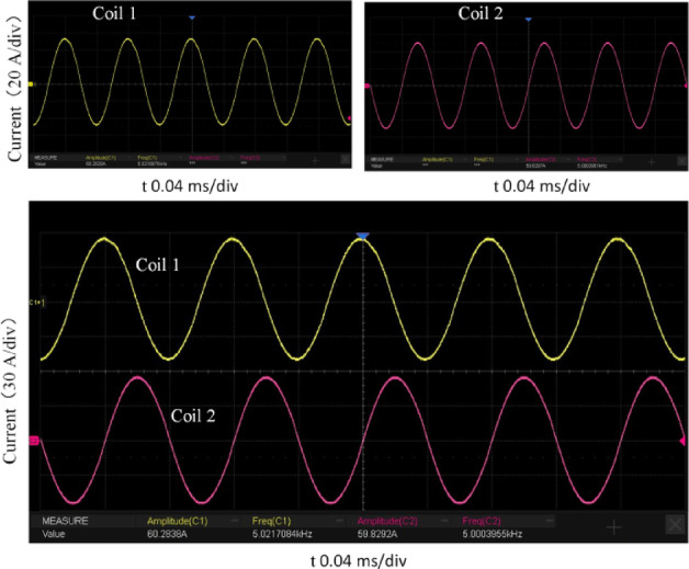
The current output from the coil is tested by inputting relevant parameters into the control chip. The switching frequencies of the two full-bridge circuits are set to 5000 Hz and 5020 Hz, respectively. The DC voltage source output is adjusted, and two identical current probes are attached to the wires of the two coils and connected to an oscilloscope. The current waveforms are shown in Fig. 14. The current waveforms on the oscilloscope are observed, and both coils exhibit standard sinusoidal current waveforms. The frequency and amplitude of the two waveforms are measured using the oscilloscope. The currents in the two coils have frequencies of 5000 Hz and 5020 Hz, respectively, and an amplitude of 60 A. These results demonstrate that the system can stably output a sinusoidal current with a fixed frequency for the coils.
Fig. 14.
Oscilloscope waveforms of coil 1 and coil 2.
After the current and frequency of the coils are examined, a physiological saline sphere model structure is established to measure the magnetic induction intensity generated by the coils within the sphere model. Notably, TI-TMS generates a time-varying magnetic field by passing a sinusoidal current through the coil, which induces a time-varying electric field in the head to stimulate specific brain targets. However, in physical experiments, the induced electric field value cannot be accurately measured by experimental instruments. Therefore, the magnetic induction intensity at specific locations in the spherical model is obtained through simulation. To ensure that the induced electric field generated by this magnetic field matches the simulation results from previous chapters, the magnetic induction intensity is measured at the corresponding position in the real saline ball model by a gaussmeter. A comparison of the test results with the simulation results verified that the magnetic field and induced electric field produced by these system coils are consistent with the simulation results. First, a simulation model is established using COMSOL as shown in Fig. 15a. Sinusoidal currents with frequencies of 5000 Hz and 5020 Hz, each with an amplitude of 60 A, are applied to the two coils. The resulting simulation outcomes are illustrated in Fig. 15b, c which shows the magnetic induction intensity distribution in the X–Z and Y–Z planes of the sphere model, respectively. Line graphs of the magnetic induction intensity along Line 1, Line 2, and Line 3 are plotted as shown by the yellow lines in Fig. 16. An experimental platform is subsequently established as shown in Fig. 15d. A Gaussmeter is used to measure and record the magnetic induction intensity along Line 1, Line 2, and Line 3 within the physiological saline sphere, with the results plotted as green lines in Fig. 16. Comparing the simulation results with the measured data in Fig. 16, the actual measured magnetic induction intensities are slightly lower than the simulation results, but the differences are minimal, and the trends in magnetic induction intensity variation are essentially consistent. Therefore, the magnetic field distribution generated by the TI-TMS system designed in this study is consistent with the simulation results.
Fig. 15.

Physiological saline sphere simulation model and experimental platform: (a) simulation model of the saline sphere model, (b) simulation results in the X–Z plane of the sphere model, (c) simulation results in the Y–Z plane of the sphere model, (d) experimental platform for the physiological saline sphere model.
Fig. 16.

Simulation results and actual measurement results of line 1, line 2 and line 3.
Discussion
To better utilise the principles of the TI in TMS technology, it is essential to first study how low-frequency envelope electric fields affect the transmembrane potential of neurons. The mechanism by which neurons respond to low-frequency envelope electric fields is debated in the literature. Grossman et al. hypothesised that the low-pass filtering properties of neurons are the fundamental mechanism behind TI stimulation and that strong kilohertz frequency fields do not (or rarely) cause conduction block in off-target tissues9. There is an ongoing healthy debate examining the clinical utility of this technology, especially considering the challenge of inefficient current penetration in large structures, such as the human head22,23. All the research results support the experimental evidence that distant neural structures can be excited in phase with the low-frequency envelope of the TI stimulus. Mirzakhalili et al. claimed, on the basis of mathematical modelling, that TI stimulation activates neurons through a nonlinear process that can “demodulate” the TI waveform and cause conduction block in off-target tissues24. Violante et al. employed electric field modeling and cadaveric measurements to demonstrate that TI stimulation can be precisely steered to target the hippocampus. And they utilized functional magnetic resonance imaging (fMRI) in conjunction with behavioral assessments to provide evidence that TI stimulation can selectively modulate hippocampal activity and improve the accuracy of episodic memory performance in healthy individuals25. Furthermore, in subsequent studies, they reported that noninvasive TI stimulation of the hippocampus can modulate hippocampal resting-state functional connectivity traces induced by a preceding hippocampus-dependent task26. Vassiliadis et al. applied TI-tACS to the right hippocampal-entorhinal complex27. The results showed that TI-tACS improved spatial navigation performance, was correlated with hippocampal activity modulation, and decreased grid cell-like activity in the entorhinal complex. Missey et al. applied TI stimulation in patients with epilepsy28. The results revealed that TI stimulation significantly decreased interictal epileptiform discharges and pathological high-frequency oscillations, specifically fast-ripples. These findings suggest TI stimulation provides promising perspectives for patients suffering from cognitive impairment, epilepsy and other neurological diseases. In the study by Adam Khalifa et al.13, the activity observed under TI stimulation was proposed to result from an “initiation response,” which typically precedes the conduction block29. They speculated that when the electric field beat envelope approaches 0 V/m, the membrane potential of neurons exposed to TI returns to its resting membrane potential, making neurons more likely to exhibit initiation responses shortly after the block. Therefore, neurons within the TI focus may generate a new initiation response with each beat cycle, whereas off-target neurons only exhibit a single initiation response and remain blocked for the duration of the continuous waveform produced by the stimulation.
This study utilises the principle of the TI to analyse the advantages of the TI-TMS over to traditional TMS. The results demonstrate advantages in terms of focusing and stimulation depth. In traditional TMS, the stimulation effect is limited by the trade-off between the induced electric field and focusing. Typically, larger coils produce greater stimulation depth but have a larger focal area, whereas smaller coils have better focusing but can stimulate only superficial layers of the induced electric field. The introduction of the TI-TMS has achieved deeper stimulation and better focusing in head models. After comparing traditional TMS with TI-TMS, this study compared the stimulation performances of TI-TMS and TI-tACS. First, regarding focality, in TI-tACS, electrodes are placed above the scalp to convey electric current into the brain tissue, and the asymmetrical geometries of the brain, as well as the tissue impedance distribution, potentially decrease the focality of the electric field generated in the target regions10. Conversely, TI-TMS can retain a constant voltage and current in the coils, thus ignoring the conductivity properties of the tissue of the subjects11. Therefore, in terms of focus, TI-TMS has considerable advantages over TI-tACS. Second, in terms of stimulation intensity, the TI-TMS system developed in this study achieves a maximum induced electric field strength of approximately 28 V/m. Traditional TMS generates strong pulsed magnetic fields, which can induce large electric fields on the scalp and potentially cause adverse effects8. In contrast, the TI-TMS system developed in this study produces a maximum magnetic flux density of less than 100 mT, which considerably reduces the risk of excessive induced electric fields and the associated side effects, thereby enhancing the system’s overall safety profile. Early work with TI-tACS in human subjects applied a total current of up to 4 mA. Assuming an electrode size of 1.5 cm2, this current translates to peak 2 mm averaged E‐field value in the brain of approximately 8 V/m in the low‐frequency range and 5 V/m for kHz exposures30. The maximum total current input for TI-tACS was limited to 10 mA for safety reasons based31, However, as the current amplitude increases, it may cause localized tissue heating, particularly at the electrode–skin contact points, potentially leading to burns. In comparison to TI-tACS, TI-TMS does not require direct skin contact, which is one of its advantages over TI-tACS. Third, regarding stimulation depth, Mo Wang et al.32 proposed a general action by framework—multiobjective optimisation by an evolutionary algorithm (MOVEA)—by optimising electrode placement, enabling TI-tACS to achieve a maximum stimulation depth of up to 6.2 cm32. In comparison, the TI-TMS system developed in this study, which uses a novel double curved-elliptical coil structure, achieves a stimulation depth of approximately 5.02 cm. This comparison suggests that TI-tACS currently has a certain advantage over TI-TMS in terms of penetration depth. However, when considering a combination of factors such as focality and stimulation intensity, TI-TMS has notable potential in overall stimulation performance compared with TI-tACS. Moreover, with further optimisation of the coil structure, the stimulation depth of the TI-TMS can be considerably improved, thereby narrowing or even surpassing the current gap in depth-related performance.
This study focuses on reaching deeper stimulation by introducing a double-curved elliptical coil structure for TI-TMS. In the designed TI-TMS system, the maximum amplitude of high-frequency current passing through the coil is 60 A, which generates a magnetic field strength sufficient to meet the minimum magnetic field required for TMS, allowing for research on weak magnetic stimulation33. However, increasing the current amplitude to meet the minimum magnetic field needed for a TMS presents challenges in the thermal management and energy consumption of the stimulation coil. Rossi et al. analysed thermal management in a traditional TMS, where the input coil current is a high-frequency pulse current with a repetition rate of 10 Hz or 20 Hz34. When the pulse current amplitude reaches 1000 A, coil heating becomes considerable. These issues become more severe since the input coil current is a continuous high-frequency sine wave for TI magnetic stimulation. Using formulas to calculate the temperature increase in the designed coil, the rate of temperature increase in the wire is given by
| 6 |
where  is in K/s, Irms is the root mean square (RMS) current in A, ρ is the resistivity of copper in Ω·m, ρCu is the density of copper in kg/m3, A is the cross-sectional area of the wire in m2, and c is the specific heat capacity of copper in J/(kg·K)35. For the coil used in this design, the cross-sectional area A = 7.06 × 10⁻⁶ m2, and the other key attributes are ρ = 1.72 × 10⁻⁸ Ω·m, ρCu = 8960 kg/m3, and c = 385 J/(kg·K). When the current amplitude Irms = 60 A, the calculated
  . Under this temperature increase, the coil can operate stably without additional cooling, although the temperature gradually increases. If the current amplitude needs to reach 500A, the coil temperature increase will reach 12.5 K/s, which is very considerable, necessitating the addition of a cooling system for the coil36. Forced liquid and gas cooling systems can be used to reduce coil heating. Additionally, incorporating ferromagnetic cores helps cool the coil and can concentrate the magnetic flux, potentially improving the penetration depth range of the activation area owing to the heat dissipation function of ferromagnetic cores37.
To verify the accuracy of the above calculations, a stimulus current with an amplitude of 60 A is passed through the coil, and the system is allowed to operate stably for 5 min. The coil temperature is measured using an infrared thermometer to analyse whether the coil can work stably and continuously without a cooling system. The temperature of the coils when the current starts to flow is shown in Fig. 17a. At this point, the average temperature of the coils, measured by the infrared thermometer, is approximately 28 °C. The temperature of the coils after 5 min of current flow are shown in Fig. 17b. At this time, the average temperature of the coil is approximately 33 °C. From these measurements, it can be concluded that when a 60 A current is passed through the coils, the temperature increase of the coils is very small. Therefore, if the coil is stimulated with a 60 A current, no need exists to add a cooling system to lower the temperature.
Fig. 17.

Temperature of the double curved-elliptical coils: (a) coil temperature at the start of stimulation, (b) coil temperature after 5 min of stimulation.
Conclusion
To analyse the advantages of the TI-TMS over the traditional TMS, this study first constructs a five-layer spherical model using COMSOL software. On the basis of this five-layer spherical model, the induced electric field distributions for different coil structures under the TI-TMS and traditional TMS are analysed. The results show that TI-TMS can address the trade-off between the focality and stimulation depth. Subsequently, double curved-elliptical coils, which are more suitable for TI-TMS, are designed to optimise the stimulation performance.
On the basis of the simulation analysis, this study designs and develops a TI-TMS system. The effectiveness of the system is demonstrated by measuring the amplitude and frequency of the coil stimulation current. The system is allowed to operate stably for a certain period, and the stability of its other aspects is observed by measuring the coil temperature confirming its practicality. This research provides a foundation for the simulation analysis of the TI-TMS mode and the development of hardware systems. This study lays the groundwork for future biological experiments using TI-TMS and offers new insights for the application of TMS in the rehabilitation of neurological diseases.
Acknowledgements
This work is supported in part by the National Natural Science Foundation of China under Grant 52320105008, and in part by the National Key Research and Development Program of China under Grant 2022YFC2402203.
Author contributions
Yanqing Zhang conceived and designed the research. Yanqing Zhang acquired and analyzed the data. Yanqing Zhang, Tingyu Wang and Chao Cui interpreted the results of the experiments. Yanqing Zhang wrote the main manuscript text and prepared the figures. Yanqing Zhang, Tingyu Wang Chao Cui and Guizhi Xu revised the manuscript.
Data availability
The data that support the findings of this study are available from the corresponding author upon reasonable request.
Declarations
Competing interests
The authors declare no competing interests.
References
- 1.Niu, Z. et al. Trial-by-trial variability of TMS-EEG in healthy controls and patients with depressive disorder. IEEE Trans. Neural Syst. Rehabil. Eng.32, 3869–3877 (2024). [DOI] [PubMed] [Google Scholar]
- 2.Zhou, H. et al. Transcranial ultrasound stimulation suppresses neuroinflammation in a chronic mouse model of Parkinson’s disease. IEEE Trans. Biomed. Eng.68, 3375–3387 (2021). [DOI] [PubMed] [Google Scholar]
- 3.Xu, X., Deng, B., Wang, J. & Yi, G. Individual prediction of electric field induced by deep-brain magnetic stimulation with CNN-transformer. IEEE Trans. Neural Syst. Rehabil. Eng.32, 2143–2152 (2024). [DOI] [PubMed] [Google Scholar]
- 4.Smith, M. C., Li, A. & Sievenpiper, D. F. A multifunction dense array system with reconfigurable depth of penetration. IEEE J. Electromagn. RF Microwaves Med. Biol.5, 35–45 (2020). [Google Scholar]
- 5.Belardinelli, P. et al. TMS-EEG signatures of glutamatergic neurotransmission in human cortex. Sci. Rep.11, 8159 (2021). [DOI] [PMC free article] [PubMed] [Google Scholar]
- 6.Fitzgerald, P. B. Targeting repetitive transcranial magnetic stimulation in depression: Do we really know what we are stimulating and how best to do it?. Brain Stimul.14, 730–736 (2021). [DOI] [PubMed] [Google Scholar]
- 7.Nurmi, S., Karttunen, J., Souza, V. H., Ilmoniemi, R. J. & Nieminen, J. O. Trade-off between stimulation focality and the number of coils in multi-locus transcranial magnetic stimulation. J. Neural Eng.18, 066003 (2021). [DOI] [PubMed] [Google Scholar]
- 8.Attal, N. et al. Repetitive transcranial magnetic stimulation for neuropathic pain: A randomized multicentre sham-controlled trial. Brain144, 3328–3339 (2021). [DOI] [PubMed] [Google Scholar]
- 9.Grossman, N. et al. Noninvasive deep brain stimulation via temporally interfering electric fields. Cell169, 1029-1041.e16 (2017). [DOI] [PMC free article] [PubMed] [Google Scholar]
- 10.Zaeimbashi, M. et al. Magnetic temporal interference for noninvasive, high-resolution, and localized deep brain stimulation: Concept validation. 10.1101/2020.07.20.212845 (2020).
- 11.Peterchev, A. V. et al. Fundamentals of transcranial electric and magnetic stimulation dose: Definition, selection, and reporting practices. Brain Stimul.5, 435–453 (2012). [DOI] [PMC free article] [PubMed] [Google Scholar]
- 12.Sorkhabi, M. M., Wendt, K. & Denison, T. Temporally interfering TMS: Focal and dynamic stimulation location. In 2020 42nd Annual International Conference of the IEEE Engineering in Medicine & Biology Society (EMBC) 3537–3543 (IEEE, Montreal, QC, Canada, 2020). 10.1109/EMBC44109.2020.9176249. [DOI] [PMC free article] [PubMed]
- 13.Khalifa, A. et al. Magnetic temporal interference for noninvasive focal brain stimulation. 10.1101/2022.01.10.475762 (2022). [DOI] [PubMed]
- 14.Xin, Z., Kuwahata, A., Liu, S. & Sekino, M. Magnetically induced temporal interference for focal and deep-brain stimulation. Front. Hum. Neurosci.15, 693207 (2021). [DOI] [PMC free article] [PubMed] [Google Scholar]
- 15.Karimi, F., Attarpour, A., Amirfattahi, R. & Nezhad, A. Z. Computational analysis of non-invasive deep brain stimulation based on interfering electric fields. Phys. Med. Biol.64, 235010 (2019). [DOI] [PubMed] [Google Scholar]
- 16.Wu, J. et al. Influence of coil orientation on the TMS-induced electric field within the clinically recommended brain region for major depressive disorder. Brain Stimulation: Basic, Translational, and Clinical Research in Neuromodulation (2025). [DOI] [PubMed]
- 17.Zhong, X. et al. Analysis of 16 coils over 50 MRI-derived head models in transcranial magnetic stimulation. IEEE Trans. Magn.57, 1–9 (2021). [Google Scholar]
- 18.Deng, Z.-D., Lisanby, S. H. & Peterchev, A. V. Electric field depth–focality tradeoff in transcranial magnetic stimulation: Simulation comparison of 50 coil designs. Brain Stimul.6, 1–13 (2013). [DOI] [PMC free article] [PubMed] [Google Scholar]
- 19.Wang, T. et al. Optimal design of array coils for multi-target adjustable electromagnetic brain stimulation system. Bioengineering10, 568 (2023). [DOI] [PMC free article] [PubMed] [Google Scholar]
- 20.Andreuccetti, D. An Internet resource for the calculation of the dielectric properties of body tissues in the frequency range 10 Hz–100 GHz. http://niremf.ifac.cnr.it/tissprop/ (2012).
- 21.Fang, X. et al. Deep brain temporally interfering magnetic stimulation via parametric characterized spatial array. AIP Adv.14, 085201 (2024). [Google Scholar]
- 22.Cao, J. & Grover, P. Do single neuron models exhibit temporal interference stimulation? In 2018 IEEE Biomedical Circuits and Systems Conference (BioCAS) 1–4 (IEEE, 2018).
- 23.Rampersad, S. et al. Prospects for transcranial temporal interference stimulation in humans: A computational study. Neuroimage202, 116124 (2019). [DOI] [PMC free article] [PubMed] [Google Scholar]
- 24.Mirzakhalili, E., Barra, B., Capogrosso, M. & Lempka, S. F. Biophysics of temporal interference stimulation. Cell Syst.11, 557–572 (2020). [DOI] [PubMed] [Google Scholar]
- 25.Violante, I. R. et al. Non-invasive temporal interference electrical stimulation of the human hippocampus. Nat. Neurosci.26, 1994–2004 (2023). [DOI] [PMC free article] [PubMed] [Google Scholar]
- 26.Kurtin, D. L. et al. Task-related changes in resting state connectivity are affected by temporal interference (Ti) stimulation. 10.2139/ssrn.5106712 (2025). [DOI] [PubMed]
- 27.Beanato, E. et al. Noninvasive modulation of the hippocampal-entorhinal complex during spatial navigation in humans. Sci. Adv.10, eado4103 (2024). [DOI] [PMC free article] [PubMed] [Google Scholar]
- 28.Missey, F. et al. Non-invasive temporal interference stimulation of the hippocampus suppresses epileptic biomarkers in patients with epilepsy: Biophysical differences between kilohertz and amplitude modulated stimulation. 10.1101/2024.12.05.24303799 (2024).
- 29.Neudorfer, C. et al. Kilohertz-frequency stimulation of the nervous system: A review of underlying mechanisms. Brain Stimul.14, 513–530 (2021). [DOI] [PubMed] [Google Scholar]
- 30.Cassarà, A. M. et al. Recommendations for the safe application of temporal interference stimulation in the human brain part II: Biophysics, dosimetry, and safety recommendations. Bioelectromagnetics46, e22536 (2025). [DOI] [PMC free article] [PubMed] [Google Scholar]
- 31.Radyte, E., Wendt, K., Sorkhabi, M. M., O’Shea, J. & Denison, T. Relative comparison of non-invasive brain stimulation methods for modulating deep brain targets. In 2022 44th Annual International Conference of the IEEE Engineering in Medicine & Biology Society (EMBC) 1715–1718 (IEEE, Glasgow, Scotland, United Kingdom, 2022). 10.1109/EMBC48229.2022.9871476. [DOI] [PubMed]
- 32.Wang, M., Lou, K., Liu, Z., Wei, P. & Liu, Q. Multi-objective optimization via evolutionary algorithm (MOVEA) for high-definition transcranial electrical stimulation of the human brain. Neuroimage280, 120331 (2023). [DOI] [PubMed] [Google Scholar]
- 33.Sekar, S., Zhang, Y., Miranzadeh Mahabadi, H., Buettner, B. & Taghibiglou, C. Low-field magnetic stimulation alleviates MPTP-induced alterations in motor function and dopaminergic neurons in male mice. Int. J. Mol. Sci.24, 10328 (2023). [DOI] [PMC free article] [PubMed] [Google Scholar]
- 34.Rossi, S., Hallett, M., Rossini, P. M., Pascual-Leone, A., Group, S. of T. C. Safety, ethical considerations, and application guidelines for the use of transcranial magnetic stimulation in clinical practice and research. Clin. Neurophysiol.120, 2008–2039 (2009). [DOI] [PMC free article] [PubMed] [Google Scholar]
- 35.Wang, W., Lu, C., Ji, X., Zhao, X. & Lyu, H. Research on overcurrent heating characteristics of copper wires at different inclination angles. J. Therm. Anal. Calorim.148, 4833–4842 (2023). [Google Scholar]
- 36.Parthoens, J. et al. Performance characterization of an actively cooled repetitive transcranial magnetic stimulation coil for the rat. Neuromodul. Technol. Neural Interface19, 459–468 (2016). [DOI] [PubMed] [Google Scholar]
- 37.Sorkhabi, M. M., Frounchi, J., Shahabi, P. & Veladi, H. Deep-brain transcranial stimulation: A novel approach for high 3-D resolution. IEEE Access5, 3157–3171 (2017). [Google Scholar]
Associated Data
This section collects any data citations, data availability statements, or supplementary materials included in this article.
Data Availability Statement
The data that support the findings of this study are available from the corresponding author upon reasonable request.