

Abstract
This paper presents a novel tri-band Multiple Input Multiple Output (MIMO) antenna module designed for millimeter and microwave frequency bands, employing metamaterial (MTM) technology to enhance performance. The compact antenna module measures 36 × 36 × 1.6 mm2 and uses a Rogers RT-5880 substrate. Its structure includes a multi-stubbed radiating patch, a partial ground plane, and a 2 × 1 epsilon-negative MTM array positioned between antenna elements in an orthogonal layout. Operating at 3.5 GHz, 5.2 GHz, and 28 GHz, the integration of MTM significantly improves the antenna’s overall performance by influencing phase, amplitude, and electromagnetic field distribution. Bandwidth enhancements of 10.01% and 6.4% are achieved for the 3.5 GHz and 5.2 GHz microwave bands, respectively, and 4.43% for the 28 GHz millimeter-wave band. Isolation levels improved from 20 dB to 24 dB in microwave bands and from 26 dB to 32 dB in the millimeter-wave band, ensuring reduced interference. The realized gain also increased from 3.6 dBi, 4.2 dBi, and 7.4 dBi to 4.8 dBi, 5.3 dBi, and 9.3 dBi across the respective frequency bands. The proposed MIMO antenna showcases excellent diversity performance with an envelope correlation coefficient (ECC) of below 0.002/0.001/0.0003 across all bands and a diversity gain (DG) exceeding 9.98 dB. Machine learning-based performance verification analysis assessed bandwidth and efficiency, where the K-Nearest Neighbors (KNN) model achieved 97.8% accuracy. This MIMO antenna holds great potential for various Internet of Things (IoT) applications, including Vehicle-to-Network, Vehicle-to-Cloud communications, 5G cellular networks, Wi-Fi, WiMAX, and both sub-6 GHz and millimeter-wave 5G bands, reinforcing its suitability for 5G IoT sectors.
Keywords: MIMO, Metamaterials, Multiband, IoT, Fifth generation, Machine learning
Subject terms: Electrical and electronic engineering, Materials science
Introduction
The integration of 5G networks and IoT devices is poised to have a remarkable effect on a broad range of wireless applications such as telecommunication, smart cities, vehicle connectivity, remote tracking, intelligent farming, rapid industrial networking, telemetry, the intelligent grid, and smart medical care1,2. The expansion of wireless connectivity for IoT applications is causing spectrum resources to become more valuable. Microwave spectrum resources are now used for long-range communications; however, they have limited data rates3. The millimeter-wave (mm-wave) band is appropriate for short-range communication because of its broad bandwidth and minimal latency4. Thus, creating an antenna module that can operate in both bands with a significant frequency ratio is the optimal alternative to fulfill the requirements of upcoming fifth-generation IoT domains5. To provide seamless and continuous connectivity between lots of handheld intelligent gadgets, it is crucial to fulfill the requirements of extremely high speeds of data and rapid response time. Using unused millimeter wave frequency channels presents an intriguing chance to address the bandwidth constraints seen in microwave frequency bands. Using the mm-wave spectrum has faced significant challenges, including high route loss, obstruction, and atmospheric losses6. Developing an outstanding performance-incorporated MIMO antenna system can successfully address these difficulties7. For successful integration of various technologies in the IoT context with 5G networks, a multipurpose is able to receive signals from many frequencies in microwave and millimeter wave bands from a single feedline is crucial. Utilizing several antennas at different frequencies leads to larger device sizes, higher costs, and more complexity. New 5G devices need to be compact, cost-effective, and straightforward. Shared aperture antennas have been studied to address this problem8,9. These antennas combine two separate antennas within a common opening, one for the sub-6 GHz range and another for the mm-wave spectrum. A recent study10 tackled the challenge of feeding both sub-6 GHz and mm-wave antennas independently in shared aperture setups by creating a single-fed triple-band antenna. This antenna operates at 3.5, 28, and 38 GHz and incorporates a MIMO structure. It offers the advantage of a unified feed for both microwave and millimeter-wave frequencies. However, it features a complicated design and is relatively large in size.
Using MIMO technology means putting several antennas in a small area. This causes them to couple up with each other and cause crosstalk, which lessens the effect of multipath fading11. The MIMO mechanism is a way to communicate wirelessly that uses more than one receiver at the transmitting and receiving ends. However, MIMO systems come with an extra problem: mutual coupling. This is when nearby antenna parts are not well separated from each other. It’s possible that this mutual coupling may negatively impact the system’s total performance12. Researchers tried a number of different methods to solve this problem and improve the gain and bandwidth, including electromagnetic bandgap (EBG), faulty ground systems, stubs with slots, MTM, and metasurfaces13–18. MTM can be used in many ways in antenna systems18. For example, to change the radiation pattern in the way you want, you might want to increase the isolation, operating band, gain, and radiation efficiency. In19, the authors used a Metamaterial-Loaded Switched-Beam Antenna Array System to make the antenna’s spread bigger. Several antennas presented in the studies20–25 exhibit notable limitations that impact their overall performance and practical applicability26–30. A common issue across these designs is the imbalance in size, where most antennas are significantly larger. The smaller antennas often struggle with poor isolation, reduced efficiency, and low realized gain, which limits their effectiveness in high-performance applications.
Additionally, the majority of antennas operate within dual-band frequencies20,21,25,30 or single-band frequencies26,28,29, lacking the capability for integrated microwave and millimeter-wave coverage. Specifically, the designs in24,27 are confined solely to the microwave band, further limiting their versatility. When comparing realized gain, most of the antennas underperform relative to the proposed design, with the exception of30, which achieves a higher gain but at the cost of a considerably larger size and a reduced efficiency of 79%. In terms of isolation, most designs offer a minimum of 22 dB at the microwave band, except for25, which achieves better isolation but at the expense of size, with dimensions of 100 × 100 mm2. For the Internet of Things (IoT) and fast wireless Internet access, we need a small MIMO antenna that has good qualities like integrated coverage of microwave and millimeter wave frequency region with low mutual coupling, high gain, and high performance. A well-known method for checking antenna data and making antennas work better is machine learning. To guess what antenna results will be, like gain, efficiency, directivity, and return loss, a lot of experts use machine learning regression models. While there aren’t any fabrication tools available, it is very helpful to use a machine learning model to check the antenna result31.
The proposed antenna addresses the above shortcomings by offering compact dimensions, improved efficiency, higher realized gain, and integrated microwave and millimeter-wave coverage, making it a more effective and versatile solution for 5G Internet of Things (IoT) applications. This research presents a multiband MIMO antenna designed for 5G Internet of Things (IoT) applications, offering enhanced performance across both microwave and millimeter-wave frequencies through a single feedline. The proposed antenna incorporates metamaterial (MTM) loading, which significantly improves isolation, gain, and efficiency while effectively reducing path loss, which is crucial for reliable IoT connectivity. The antenna achieves wide operational bandwidths in microwave and millimeter-wave regions, covering 2.8–3.8 GHz and 4.5–5.6 GHz in the microwave band, and 25.5–29.7 GHz in the millimeter-wave band. This is accomplished by integrating a dual stub with a patch structure, optimizing frequency response, and bandwidth coverage. The broad operational range enables the antenna to support a wide array of IoT applications, making it highly versatile and adaptable to emerging communication needs. Specifically, it caters to WiMAX32, WLAN33, 5G cellular networks34,35, 5G Wi-Fi23, and 5G sub-6 GHz bands (N77, N78, N79)36, as well as the 5G millimeter-wave band37. The efficient multiband operation and improved antenna parameters position this design as a robust solution for next-generation IoT networks, facilitating seamless communication and improved data transfer rates across diverse frequency bands. Building on the versatility of the proposed multiband MIMO antenna for 5G IoT applications, its ability to operate across both microwave and millimeter-wave frequency bands makes it highly suitable for advanced Internet of Vehicles (IoV) systems. Cellular networks, known for their large capacity and extensive coverage38, are crucial in supporting IoV. Cellular vehicle-to-everything (C-V2X) systems leverage cellular network spectrums to facilitate vehicle-to-network (V2N) and vehicle-to-cloud (V2C) communications39. By utilizing both microwave and millimeter-wave bands, the proposed antenna can optimize C-V2X communications, ensuring seamless, high-speed, and reliable connectivity in future IoV ecosystems. To improve the isolation, bandwidth, and gain of the entire antenna in a very small form factor, we employed an epsilon negative metamaterial in the proposed MIMO antenna. Furthermore, we have used the machine learning regression technique to validate the efficiency and bandwidth of our single-element antennas. The suggested work stands out from past investigations and is well-suited for easy integration into the Internet of Things devices with 5G technology because it introduces a quad-port MIMO antenna solve that is innovative in its geometry, tightly packed, able to offer multi-band communications with a broad-spectrum ratio, and outstanding radiation feature.
Development of micro-wave and mm-wave single element antenna
By connecting four stubs with a rectangle-shaped patch and a partial ground, the suggested antenna with a single element is built. In the microwave region (3.5 GHz, 5.2 GHz), two L-shaped stubs are connected to the upper side of the patch, while two stubs are located on the lower side of the patch and operate collectively in the mm wave band (28 GHz). In the CST simulation tool, the antenna is designed in Rogers RT-5880 Substrate with a very compact form factor (13 × 15 × 1.6 mm3) and a dielectric property of εr = 2.2 and tan δ = 0.0009. Figure 1 illustrates the configuration of the single element antenna. The frequency at three bands is achieved by optimizing the length of each stub, feedline, and rectangular patch. Every parameter has the following optimal values: L1 = 3.5, L2 = 5, L3 = 1.11, L4 = 5.1, L5 = 7, L6 = 0.3, L7 = 0.6, L8 = 15, L9 = 2.9, W1 = 2.2, W2 = 0.4, W3 = 12, W4 = 0.4, W5 = 0.6, W6 = 6.4, W8 = 9.2, and W1 = 2.2 (mm as the unit).
Fig. 1.

Front and back schematic of the single element antenna with dimension.
The initial layout was done with a fundamental rectangular shape patch that incorporated a partial ground working at a frequency (fr) of 5 GHz. In accordance with the concept of the transmission line method, the width (W3) of the patch can be estimated by Eq. (1)40.
 |
1 |
wherein c is the speed of light in empty space, and εr is the dielectric value of the antenna substrate.
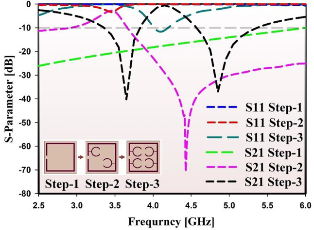
Once that is done, L-shaped stubs are connected to the main patch to make an antenna with various resonance frequencies in the microwave band. The little stubs at the bottom of the patch are made for the mm-wave band. Figure 2 shows how the suggested antenna’s design changed over time and what its s-parameters (S11) are. It is known that the side length of all of these antennas is the same. First, an L-shaped stub with a width of W5 is added to the left side of the main patch to set the frequency at 3.5 GHz. Then, another L-shaped patch stub is added 1 mm away from the first one to move the 5 GHz resonance frequency to 5.2 GHz. At 28 GHz, two I-shaped stubs are vibrating together. Because of the first patch, there is one reverberation at 5 GHz at step-1. The following Eqs. (2), (3), and (4) are used to figure out the total length of the stubs:41,
| 2 |
| 3 |
| 4 |
Fig. 2.

Single element evolution with respective S11 and fabricated prototype.
With a bandwidth of (3.1–3.8) GHz, (4.8–5.6) GHz, and (26.3–29.3 GHz), the antenna oscillates at three different frequencies: 3.5 GHz, 5.2 GHz, and 28 GHz. From the current pattern shown in Fig. 3, we can show the resonance frequencies. From the current distribution, we can see that the big L-stub on top of the patch radiates strongly at 3.5 GHz, while the small one radiates strongly at 5.2 GHz. At the optimum frequency of 28 GHz, the I-stubs are giving off a lot of radiation. The single element antenna has a maximal gain of 2.8 dBi at 3.5 GHz, 3.5 dBi at 5.2 GHz, and 6.3 dBi at 28 GHz. In all three bands, the single element’s efficiency ranges from 65 to 75%. Figure 4 shows the realized gain and radiation efficiency measured and simulated at (a) the micro-wave band and (b) the mm-wave band.
Fig. 3.
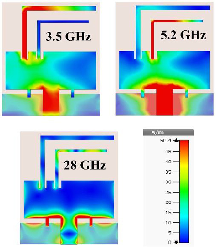
Current distribution at respective resonant frequency.
Fig. 4.

Realized gain and efficiency of the proposed single element antenna.
Development of 4 × 4 MIMO antenna
When designing a 4 × 4 MIMO antenna, the antenna components are placed in an orthogonal direction to reduce coupling between them. Each antenna is spaced just 9 mm apart. To address surface currents and manage nearfield coupling issues, a distinct ground plane is utilized42. Due to the proximity of the antenna elements, it is essential to disconnect the ground plane of MIMO module or implement a complex decoupling technology. Considering the compact layout of the four elements, it was decided to opt for a separate ground plane to streamline the antenna’s intricacy. Constructed on a 36 × 36 × 1.6 mm3 substrate. Here are the front and back views of the MIMO antenna as depicted in Fig. 5 (a) and (b). Figure 5 (c) and (d) show the measurement setup.
Fig. 5.

Schematic design and measurement setup of 4 × 4 MIMO antenna.
Based on the simulated S-Parameter, the antennas demonstrate operation at three resonance frequencies within specific bandwidths in the micro and mm-wave oscillation area, as shown in Fig. 6 (a) and (b). The MIMO configuration offers isolation of over 20 dB across all three working bands. Given that the transmission coefficients |S21| and |S41| are the same, we will only focus on |S21| and |S31| as isolation characteristics. Moreover, the antennas nearby exhibit similar simulated isolation characteristics because of their architectural structure. As a result of geometric uniformity, the antenna’s reflection coefficients (|S11|, |S22|), (|S33|, |S44|) are also consistent for all neighboring antennae, resulting in only |S11| being the reflection coefficient. Figure 7 (a) and (b) shows the gain and efficiency of the MIMO antenna, measured and simulated at micro-wave and mm-wave frequencies. Observing the peak gain values at 3.5 GHz, 5.2 GHz, and 28 GHz reveals gains of 3.6 dBi, 4.2 dBi, and 7.4 dBi correspondingly. The efficiency ranges from 70 to 84% across all three operating bands. The simulated and measured results exhibit a strong resemblance. Nevertheless, the simulated and measured outcomes may not align perfectly because of fabrication and measurement errors.
Fig. 6.

S-parameter of the 4 × 4 MIMO antenna (a) Microwave band, (b) Mm-wave band.
Fig. 7.

Realized gain, and efficiency of the 4 × 4 MIMO antenna (a)Microwave band, (b) Mm-wave band.
Development of metamaterial loaded 4 × 4 MIMO antenna
Utilizing metamaterials offers a powerful method to improve the radiation capabilities of antennas, including the realized gain, operated-bandwidth, and mutual coupling between MIMO radiating elements. Metamaterials have a notable impact on surface waves, resulting in the emergence of extra resonance phenomena that boost antenna performance43. The development of a metamaterial (MTM) loaded MIMO antenna starts with the design of a unit cell MTM. This unit cell MTM is then strategically placed between the MIMO antenna elements to enhance the performance of the proposed system. Leveraging the lowest resonance frequency as a guiding parameter, this study introduces a novel 1.6 mm thick negative epsilon metamaterial (MTM) unit cell using Rogers RT-5880 substrate. The design evolution is illustrated in Fig. 8, where step-by-step modifications are detailed. Initially, in step-1, the MTM resonator comprises a square-shaped box with a strategically positioned slot on its left side. Advancing to step-2, two C-shaped resonators are integrated, connected to the box resonator, and arranged in a face-to-face configuration, yielding a single resonance frequency. To achieve dual resonance, step-3 incorporates an additional pair of C-shaped resonators coupled with the box resonator. The corresponding S-parameters of these evolution stages are depicted in Fig. 9, with the final design operating at 3.5 GHz and 5 GHz. This innovative design offers promising performance. We can calculate the unit cell resonant frequency () by using the Eq. (5)44.
 |
5 |
Fig. 8.

Evolution step of the unit cell MTM.
Fig. 9.
S-parameters of the proposed unit cell at different stages.
Where, C indicates Capacitance, and L indicates Inductance.
Figure 10 (a) and (b) presents the dimensional front and back view of the antenna. There is a square-shaped resonator at the back of the unit cell as shown in Fig. 10 (b). The final optimized values are presented in Fig. 7(a) and (b), with specific dimensions for each component. Where, = 4 mm, L = 4 mm, 1 = 3.2 mm, W2 = 0.05 mm, W3 = 0.02 mm, W4 = 0.04 mm, L1 = 0.5 mm, L2 = 0.4 mm, L3 = 1.2 mm, and L4 = 0.09 mm. Figure 10 (c) illustrates the fabricated prototype of the proposed MTM unit cell.
Fig. 10.

Proposed MTM (a) front view, (b) back view and (c) fabricated prototype.
Figure 11(a) shows the measurement setup for the proposed MTM unit cell, while Fig. 11(b) compares the simulated and measured S-parameters. To measure the proposed unit cell, a vector network analyzer (VNA) is used, and MTM under test (MUT) is placed between two waveguide ports in the z-axis as shown in Fig. 11 (a). The first resonance is nearly identical between simulated and measured data, demonstrating strong agreement. However, the second resonance exhibits some deviation. This difference is attributed to simulation assumptions, which include precise dimensions, ideal material properties, and perfect electromagnetic modeling. In practice, manufacturing tolerances introduce slight variations in geometry and substrate characteristics. Moreover, real-world material parameters, such as dielectric constants, may differ from nominal values. Measurement issues like calibration errors and environmental interference affect results. These factors underscore the importance of accounting for variations in antenna design evaluation.
Fig. 11.

(a) Measurement setup and (b) Simulated and measured s-parameter of the proposed MTM.
Electromagnetic properties, such as surface current distribution and magnetic and electric fields, are critical for evaluating the performance of the metamaterial (MTM). Figure 12 displays the surface current, magnetic, and electric field distributions at 3.5 GHz. The highest current density is observed on the box resonator, then flows through the adjacent C-shaped resonators. The H-field distribution reveals that magnetic fields arise as currents traverse these regions, while significant electric fields are concentrated along the frame and at the junction between the box and C-shaped resonators. This behavior demonstrates effective energy coupling within the MTM, which is essential for optimizing antenna performance and overall device efficiency.
Fig. 12.

Electromagnetic properties of the proposed MTM unit cell at 3.5 GHz.
Understanding the effective permeability, permittivity, and refractive index of a Metamaterial is crucial. Using the post-processing capabilities in the CST simulation tool, we were able to analyze the characteristics of these items. Nevertheless, we overlook permeability analysis due to its positive characteristics. The MTM effective numbers are obtained from the scattering variables through a reliable retrieval method. Equations (6) and (7) can be used to find the reflection coefficient and transmission coefficient45.
| 6 |
| 7 |
By applying Eqs. (6) and (7), on Eqs. (9) and (10), the refractive index and impedance is calculated46.
| 8 |
| 9 |
Here, ‘m’ represents the actual refractive index value. We can figure out the values of permittivity and permeability by using Eqs. (10) and (11).
| 10 |
| 11 |
Figure 13 (a), (b) and (c) are crucial visual aids for grasping the characteristics of the proposed metamaterial. The intriguing aspect of the effective permittivity () can be observed in Fig. 13 (a), demonstrating its continuous negativity across the entire simulated band. This indication of negative epsilon suggests that the metamaterial has the potential to display epsilon-negative (ENG) characteristics. This characteristic has important implications for antenna development and performance. Figure 15(b) illustrates the permeability (µ) of the proposed MTM unit cell, which remains positive throughout the entire frequency band, confirming the unit cell’s characteristics as Epsilon-Negative (ENG). Figure 13(c) depicts the refractive index (), showing a negative value between 3.49 GHz and 3.7 GHz. Outside this range, the refractive index approaches zero or becomes positive. This conflicting behavior suggests the potential for unconventional and highly adaptable control of electromagnetic waves. Being able to manipulate the refractive index enables unique wave front adjustments and beam propagation in different scenarios. It’s important to focus on the distinctive advantages of the metamaterial due to its negative effective permittivity18, rather than the more common characteristics of the permeability’s effectiveness (), which lacks negativity or values close to zero. The acquired permittivity confirms the ENG characteristics of the metamaterial, suggesting its potential for enhancing antenna performance47.
Fig. 13.

Effective parameters of the proposed MTM unit cell (a) permittivity, (b) permeability and (c) refractive index.
Fig. 15.

Schematic Model and measurement setup of 4 × 4 MIMO antenna with MTM.
The dispersion diagram of the proposed structure was analyzed using Eq. (12) to gain a deeper understanding of the metamaterial’s behavior and its electromagnetic wave propagation properties.
| 12 |
….
Here,
 = 2πf (Angular frequency)
C = Speed of light.
 = Permittivity of the metamaterial (Real part)
 = Permeability of the metamaterial (Real part)
Figure 14 shows the dispersion diagram of the proposed MTM structure. The dispersion diagram indicates that the metamaterial has two resonance frequencies at 3.6 and 4.9 GHz, where the wave vector experiences significant changes. These resonances are characteristic of metamaterials designed to interact strongly with electromagnetic waves at specific frequencies. The sharp rise in the wave vector at these points suggests that the material is optimized to manipulate wave propagation at these frequencies.
Fig. 14.
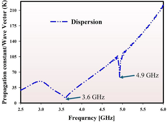
Dispersion diagram of proposed MTM using wave vector.
Figure 15 represents the geometric layout and method of exciting the MIMO antenna loaded with MTM, as detailed in this research. Figure 15 (a) shows the front view of the 4 × 4 MIMO antenna with MTM being loaded, while (b) displays the back view. Developed a 2-element MTM array to enhance the performance of the MIMO system by placing it between antenna elements. The antenna is designed to be very compact, measuring 36 × 36 × 1.6 mm3, and is created using a Rogers Rt-5880 Substrate. The MTM array is strategically positioned at an equal distance among the two nearest antenna elements to boost the MIMO antenna’s performance. To achieve the best possible realized gain and mutual coupling among MIMO parts, it is essential to run multiple rounds of simulations to find the appropriate distance between the antenna and the MTM array, taking into account the required 1/4 wavelength. Using a vector network analyzer (VNA), the features of propagation are analyzed in Fig. 15 (c), and radiation in the near-field capabilities is studied and measured in an anechoic chamber, as shown in Fig. 15 (d).
Through simulation and actual testing, it is confirmed that the MTM significantly enhances the effectiveness of the MIMO antenna. Figure 16 (a) and (b) show the S-parameters of the MIMO antenna loaded with MTM, while Fig. 17 (a) and (b) present the realized gain and radiation efficiency of the antenna. It’s evident that the achieved gain is around 4.8 and 5.3 dBi in the microwave band and 9.3 dBi in the millimeter-wave band. The isolation exceeds 24 dB in the microwave band and surpasses 32 dB in the millimeter-wave band.
Fig. 16.

S-parameter of the 4 × 4 MIMO antenna with MTM (a) Microwave band (b) Mm-wave band.
Fig. 17.

Realized gain, and efficiency of the suggested 4 × 4 MIMO antenna with MTM (a) Microwave band (b) Mm-wave band.
Result analysis and discussion
In this section, the progression of the outcome has been demonstrated from a single-element to a quad-element MIMO antenna enhanced with MTM.
Figure 18 (a) and (b) show the comparison of the S-parameter in microwave and millimeter-wave. The bandwidth expands as the antenna transitions from a single element to a 4 × 4 MIMO configuration loaded with MTM. Specifically, there is a 10.01% and 6.4% increase in the microwave band (at 3.5 GHz and 5.2 GHz resonant frequencies, respectively), and a 4.43% increase in the mm-wave band at 28 GHz resonant frequency. Furthermore, the minimum isolation is 20 dB in the microwave band and 26 dB in the millimeter-wave band for the MIMO antenna without MTM. This isolation improves to 24 dB in the microwave band and 32 dB in the millimeter-wave band when the MTM feature is included.
Fig. 18.

S-parameter evolution from single element to 4 × 4 MIMO antenna with MTM.
Figure 19 (a) and (b) show the comparison of gain and efficiency. For a single element, the achieved gains are 2.8 dBi, 3.5 dBi, and 6.3 dBi at 3.5 GHz, 5.2 GHz, and 28 GHz, respectively. Enhanced MIMO setup without MTM to achieve gains of 3.6 dBi, 4.2 dBi, and 7.4 dBi. MTM allows for achieving maximum realized gains of 4.8 dBi, 5.3 dBi, and 9.3 dBi. The efficiency ranged from 78 to 84% without MTM, and increased to 82–91% with MTM across all three operating bands.
Fig. 19.

Realized gain and efficiency improvement from single element to a 4 × 4 MIMO antenna with MTM.
Figure 20 shows the surface current dispensation of the MIMO configuration loaded and without loaded metamaterial. We can observe the isolation from the current distribution as well. Based on the current distribution at 3.5 GHz, it is evident that exciting antenna 1 without MTM results in surface current being distributed to antenna 3, which is reduced in the presence of MTM between antenna elements. At 5.2 GHz, the current flows through antenna 2 and antenna 4 without using MTM. However, when MTM is used, less current passes through the other elements. The MTM functions for the 28 GHz band as well, and less current flows through other antennas when there is an MTM array.
Fig. 20.

Current distribution comparison of 4 × 4 MIMO antenna with and without MTM.
Figure 21 depicted the evaluated and Simulated 2D radiation characteristics of the suggested antenna with and without MTM. These patterns are for the E-plane in the yz and xz directions within phi = (90, 0) and the H-plane in the xy and theta = 90. Because the four antennas are arranged in an orthogonal fashion, each port exhibits the same radiation behavior with pattern variety. Here, we present the normalized radiation pattern for port 1. Since the ground is not full ground, the antenna shows good omni directional characteristics in the far-field scenario. The other elements serve as a reflector when port 1 is activated. There is a little difference in pattern direction with and without MTM. The radiation properties spread more when there is MTM. However, there is some scattering at 28 GHz due to high frequency. The existence of pattern diversity is demonstrated by the fact that the ports exhibit radiation patterns that are complementary to one another.
Fig. 21.

2D radiation Pattern of 4 × 4 MIMO antenna with and without MTM.
Evaluating MIMO antenna performance and capability involves assessing the diversity attributes. By evaluating the Envelope Correlation Coefficient and Diversity Gain, the MIMO diversity performance of the recommended antenna is analyzed48. Utilizing the far-field radiation pattern method49 allows for the calculation of the ECC, a crucial metric for assessing the correlation between radiation patterns of various antennas. We can determine the ECC of the proposed MIMO antenna by using Eq. (13).
| 13 |
and 
Mostly, 0.0 is considered the optimal number of ECC for a not significantly changed MIMO configuration50. Still, it is recommended to be maintained at less than 0.5 in an experiential MIMO module for as long as feasible. The ECC value of the suggested four-element MIMO antenna is illustrated in Fig. 22 (a) for micro-wave and (b) for mm-wave, indicating strong diversity performance with and without MTM. With MTM the archived ECC value is < 0.002/0.001/0.0003 for all three bands.
Fig. 22.

ECC of the suggested 4 × 4 MIMO antenna with and without MTM.
Understanding the Diversity Gain (DG) is crucial for evaluating the performance and capabilities of the MIMO antenna. The mathematical relationship among the components of the antenna causes a  reduction in the diversity performance of an MIMO system. Hence, Eq. (14) can be used to determine the diversity gain of a MIMO antenna with coupled antenna parts51,
| 14 |
10 dB is the optimal point for DG. The suggested antenna maintains a DG of > 9.99 dB throughout its entire operational frequency range with and without MTM, as illustrated in Fig. 23 (a) for microwave and (b) for millimeter-wave. Table 1 shows the output progression of the antenna design across three operating bands, from one element to four elements MIMO with MTM antenna, which is presented in Table 1 in a concise manner.
Fig. 23.

DG of the suggested 4 × 4 MIMO antenna with and without MTM.
Table 1.
Progression of performance: single element to 4 × 4 MIMO antenna with MTM.
| Antenna type | Single element | 4 × 4 MIMO without MTM | 4 × 4 MIMO with MTM |
|---|---|---|---|
| Bandwidth [GHz] | 3.1–3.8/4.8–5.6/26.3–29.3 | 3.09–3.85/4.6–5.6/26-29.3 | 2.8–3.8/4.5–5.6/25.5–29.7 |
| Gain [dBi] | 2.8/3.5/6.3 | 3.6/4.2/7.4 | 4.8/5.3/9.3 |
| Efficiency [%] | 71/75/71 | 80/78/84 | 86/82/91 |
| Isolation [dB] | – | > 20/21/28 | > 24/26/32.5 |
| ECC | – | < 0.002/0.001/0.0007 | < 0.002/0.001/0.0003 |
Machine learning (ML) verification and analysis
Over the past decade, the integration of machine learning (ML) into antenna design and validation processes has brought transformative changes, leading to significant advancements and practical applications in the field52–54. Researchers and engineers have increasingly explored ML techniques to optimize various stages of antenna development, ranging from initial design to final performance validation. By leveraging data-driven models, ML can effectively analyze vast amounts of data collected from simulated antennas, identifying patterns and insights that traditional methods might overlook55,56. This capability has made ML an invaluable tool in addressing the inherent complexities and uncertainties in antenna fabrication and testing. Antenna design has traditionally followed a sequential process involving simulation, prototype fabrication, and performance measurement. While this conventional approach has proven effective, it often demands extensive resources, including high-cost materials, specialized fabrication equipment, and multiple rounds of prototyping to fine-tune performance metrics such as bandwidth, efficiency, and return loss. In many cases, discrepancies between simulation results and real-world measurements emerge due to manufacturing imperfections. For instance, an antenna design exhibiting wide bandwidth in simulations may yield poor or no bandwidth in its fabricated form, leading to wasted resources and extended development timelines. The incorporation of ML into this process addresses these challenges by enhancing the predictive accuracy of simulations, thereby reducing the reliance on costly and time-consuming physical prototyping. By applying advanced ML models, particularly supervised regression techniques, designers can forecast critical performance parameters, such as the realized gain of an antenna more reliably before proceeding to fabrication. This predictive capability not only minimizes the number of prototype iterations required but also makes the design process more accessible to researchers and students in economically constrained regions who may lack the resources for extensive trial-and-error methods. In this study, ML forecasting was employed to validate the realized gain of the proposed single-element antenna, demonstrating the effectiveness of supervised regression strategies in achieving accurate performance predictions. The integration of ML into antenna design not only streamlines the development process but also offers a cost-efficient alternative that democratizes access to advanced antenna research, fostering innovation across diverse regions and academic institutions.
There are two stages involved in implementing machine learning for antenna design. First, it’s important to collect the necessary data for training machine learning models efficiently. When developing a triple-band antenna, it’s necessary to perform parametric sweeps on critical components such as stubs length, stubs width, slot length, patch length, patch width, and feed lengths of the antenna. These components have a significant impact on the overall performance of the antenna. By utilizing simulation through CST MWS, a total of 345 data samples have been gathered. During the second phase, different regression machine learning algorithms are used to predict bandwidth and efficiency. The dataset is separated into training and testing sets, with 80% assigned to training and 20% to testing, in accordance with statistical principles57. Three regression models - Decision Tree Regression (DTR), K-Nearest Neighbors (KNN), Random Forest Regression (RFR) - are being evaluated for their effectiveness in non-linear regression analysis. Google Collab is used for machine learning research. The methodology is depicted in a flowchart in Fig. 24.
Fig. 24.

Machine Learning Methodology flowchart.
ML algorithms and metrics for evaluating ML performance
One kind of machine learning technique, known as random forest regression58,59, employs a group of decision trees to carry out regression operations. In order to improve accuracy and decrease overfitting, it combines the predictions of several trees. It builds a diversified set of models for robust predictions by randomly picking subsets of data and attributes for each tree.
A non-parametric supervised learning approach called K-Nearest Neighbors (KNN) regression is used to estimate the continuous values of a target variable by averaging the values of its k nearest neighbors in the feature space.
We can build regression or classification models with the help of a decision tree. In decision tree regression60, a model is trained to fit within a tree framework that evaluates an item’s properties. Future data forecasts and consistently useful outputs are made possible by this approach.
The error rate is a key statistic in regression analysis. This study extensively evaluated various machine learning algorithms using diverse statistical metrics to measure their performance. The accuracy of predictions was evaluated using R-squared (R2) and the explained variance score, along with MSE, MAE, and MSLE as the selected error metrics for the machine learning process. We can determine these error matrices by utilizing the equations numbered (15), (16), and (17)61.
| 15 |
| 16 |
| 17 |
Where n = number of errors,  = error absolute.
And the accuracy matrices can be evaluated by applying the Eqs. (18) and (19)57.
| 18 |
| 19 |
Bandwidth verification analysis
For verifying the bandwidth with machine learning process, three regression methods have been selected for comparison and contrast in Table 2: Decision Tree Regression (DTR), K-Nearest Neighbors (KNN), and Random Forest Regression (RFR). Several metrics such as mean absolute error (MAE), mean squared error (MSE), and mean squared logarithmic error (MSLE), are employed for error evaluation, while R-squared and variance score are utilized to assess the accuracy of each models. Moreover, a bar chart comparing the accuracy of the models is depicted in Fig. 25 (a) for microwave and (b) for mm-wave. The mean absolute error (MAE), mean squared error (MSE), and mean squared logarithmic error (MSLE) scores of the KNN model are exceptionally low at 0.00762%, 0.000234%, and 0.000073% respectively for micro-wave. Furthermore, the error matrices in mm-wave are all less than 0.02%. Moreover, KNN attains the highest achievable R-squared and variance score, boasting an accuracy of 97.8% and 98% for micro-wave, and over 98% for mm-wave. Figure 26 illustrates the discrepancy among the simulated and predicted bandwidth for KNN using a set of 78 test samples, with the difference being almost negligible. Moreover, the typical error rate is below 0.1%. Furthermore, every Regression model shows an accuracy of 95.3% or higher for both micro-wave and mm-wave. Given the close match among the predicted and simulated results, it can be inferred that the antenna bandwidth aligns well with the simulation, as depicted in Fig. 26.
Table 2.
Machine learning performance metrics for bandwidth verification in micro-wave and mm-wave.
| Band | Algorithms | MAE (%) | MSE (%) | MSLE (%) | R2 (%) | Var score (%) |
|---|---|---|---|---|---|---|
| Bandwidth | ||||||
| Micro-wave band | DTR | 0.00875 | 0.000286 | 0.000093 | 96.1 | 96.1 |
| KNN | 0.00762 | 0.000234 | 0.000073 | 97.8 | 98.0 | |
| RFR | 0.00829 | 0.000265 | 0.000080 | 96.6 | 96.8 | |
| Mm-wave band | DTR | 0.03999 | 0.008451 | 0.000413 | 97.0 | 97.1 |
| KNN | 0.02915 | 0.004395 | 0.000230 | 98.0 | 98.0 | |
| RFR | 0.04539 | 0.010244 | 0.000550 | 95.3 | 95.4 | |
Fig. 25.

Accuracy bar chart of bandwidth verification.
Fig. 26.

Predicted and tested comparison of bandwidth verification for KNN model.
Efficiency verification analysis
To confirm the efficiency, we selected identical models with matching error and accuracy matrices, similar to bandwidth verification. Table 3 presents a comparison of the error and accuracy for all models. Similar to bandwidth verification, the KNN model has demonstrated exceptional performance with an error value of less than 0.00067% for microwave and less than 0.00148% for mm-wave across all error metrics. KNN demonstrates exceptional accuracy performance, exceeding 97.9% in both micro-wave and mm-wave matrices. Furthermore, a bar chart comparing the effectiveness of the models is displayed in Fig. 27. KNN has utilized almost 69 test samples, and the outcomes are presented in Fig. 28 alongside the simulated and predicted efficiency. Figure 28 illustrates the KNN model’s simulated and expected efficiency levels are nearly identical, near to zero. Hence, the illustration of the simulated result and the anticipated outcome are highly similar. Other models have achieved accuracy rates exceeding 95.1%. It’s clear that the KNN technique stands out as a highly promising model for assessing efficiency with this dataset, and the efficiency achieved through simulation is dependable.
Table 3.
Machine learning performance metrics for efficiency verification in micro-wave and mm-wave.
| Band | Algorithms | MAE (%) | MSE (%) | MSLE (%) | R2 (%) | Var score (%) |
|---|---|---|---|---|---|---|
| Efficiency | ||||||
| Micro-wave band | DTR | 0.00126 | 0.000006 | 0.0000024 | 95.9 | 95.1 |
| KNN | 0.00067 | 0.000002 | 0.000001 | 99.0 | 99.0 | |
| RFR | 0.00124 | 0.000005 | 0.000002 | 97.3 | 97.4 | |
| Mm-wave band | DTR | 0.00180 | 0.000010 | 0.000003 | 96.6 | 96.7 |
| KNN | 0.00148 | 0.000010 | 0.000003 | 97.9 | 98.0 | |
| RFR | 0.00209 | 0.000020 | 0.000007 | 95.4 | 95.7 | |
Fig. 27.

Accuracy bar chart of efficiency verification.
Fig. 28.

Predicted and tested comparison of efficiency verification for KNN model.
Performance comparison of proposed antenna with current literature
The state-of-the-art comparison of the proposed antenna with recent literature is presented in Table 4, highlighting its competitive performance in terms of size, gain, isolation, and integrated microwave and millimeter-wave coverage. A significant portion of the referenced works focuses solely on single-frequency operations. Specifically, antennas in studies21,24,27,62 are designed exclusively for the microwave band, while those in26,28,29 are tailored for the millimeter-wave band. These single-band antennas, though efficient in their targeted frequency ranges, fall short in supporting the growing demand for multiband operations, especially in 5G IoT applications, where seamless connectivity across various frequency bands is essential. To bridge this gap, some studies20,22,23,25,30 have explored designs capable of covering both the microwave and millimeter-wave bands. However, these efforts often come with trade-offs. In20, the researchers utilized a low-pass filter to extend coverage across both bands. While effective in achieving dual-band operation, the inclusion of the filter significantly increased the antenna’s size. Furthermore, despite the broader frequency range, the design suffered from lower gain and suboptimal isolation compared to the proposed antenna. Another notable attempt is seen in22, where a tri-band dual-port antenna was designed for both microwave and millimeter-wave operations. Although this design offers a compact size primarily due to the two-port MIMO configuration, it compromises performance in terms of realized gain and isolation, both of which are lower than those of the proposed antenna. In the broader comparison, most antennas that manage to cover both frequency ranges tend to either suffer from lower gain and isolation or require a larger form factor. For instance, the study in30 achieved a high realized gain through the use of metamaterial (MTM) structures. However, this came at the expense of lower isolation, reduced efficiency, and an overall larger antenna size compared to the proposed design. Specifically, while the realized gain in30 surpassed that of the proposed antenna, its efficiency lagged, and its bulkier form factor limits its applicability in compact IoT devices. Isolation is a critical parameter in MIMO antenna performance. Many designs recorded isolation values of only 22 dB at the microwave band and 30 dB at the millimeter-wave band. Notably, the design in25 achieved an improved isolation of 25 dB but required a significantly larger antenna with dimensions of 100 × 100 mm², making it less suitable for compact IoT applications. Efficiency is another essential factor in evaluating antenna performance. While some antennas in the comparison exhibit efficiency rates ranging from 80 to 90%, certain designs fall short. For instance25,30, display lower efficiency rates, limiting their overall performance. The study in24 achieved the highest efficiency of 98%, but this came with limitations. The antenna operates solely within the microwave band and exhibits a low realized gain. Meanwhile, the design in28 employed a Defected Ground Structure (DGS) to enhance MIMO performance within the millimeter-wave band. Although the DGS improved isolation to 21 dB, this value remains below the optimal threshold for millimeter-wave communications. Additionally, the realized gain was only 6.65 dBi, and the antenna size was comparable to that of the proposed design, making it less efficient in terms of performance-to-size ratio. Another technique explored in the literature is the use of Electromagnetic Band Gap (EBG) structures, as seen in62. The EBG-based design achieved isolation levels comparable to the proposed antenna, but this was primarily due to its simpler two-port configuration. While high isolation was achieved, the realized gain was notably lower than that of the proposed design, limiting its effectiveness in high-performance IoT applications. A unique aspect of the proposed design is the integration of Machine Learning (ML) for performance validation. None of the antennas reviewed in the comparison employed ML techniques to predict or validate key performance metrics such as bandwidth, efficiency, and gain. The proposed antenna successfully combines several advanced features into a compact design. With its integrated microwave and millimeter-wave coverage, the antenna offers wide operational bandwidths of 2.8–3.8 GHz and 4.5–5.6 GHz in the microwave band, and 25.5–29.7 GHz in the millimeter-wave band. The use of MTM structures significantly enhances both gain and isolation, while the compact dimensions make it suitable for next-generation IoT devices and vehicular communication systems. The proposed antenna demonstrates superior performance in terms of size, gain, isolation, and integrated frequency coverage when compared to existing designs. It successfully addresses common challenges in antenna design, such as maintaining high efficiency and wide bandwidth within a compact form factor, while also incorporating innovative validation techniques like ML. This makes the proposed antenna a highly competitive solution for modern 5G IoT applications and other emerging wireless communication systems.
Table 4.
Performance comparision with recent literature.
| References | Technique | Frequency [GHz] | Realized gain [dBi] | Isolation [dB] | Efficiency [%] | ECC | No of port | Size(mm2) | Microwave and MMW coverage | ML verification |
|---|---|---|---|---|---|---|---|---|---|---|
| 20 | Low pass filter | 3.5/26 | 3.8/7.5 | > 20/26 | 85/90 | – | 4 | 154 × 66 | Yes | No |
| 21 | Modified hexagonal patch | 2.85/5.34 | 1.72/4.5 | > 15 | 80 | < 0.05 | 4 | 50 × 50 | No | No |
| 22 | Decoupling wall | 3.5/5.3/28 | 3.46/4.15/6.2 | > 20/28 | 85/95 | < 0.01 | 2 | 32 × 22 | Yes | No |
| 23 | Passive decoupling structure | 5.5/17/35.5 | 3.05/5.27/6.97 | > 20 | 90 | < 0.007 | 4 | 30 × 30 | Yes | No |
| 24 | Shorting pins | 1.2/3.5/5.2 | 1.5/2.8/4 | > 20 | 98/93/92 | < 0.02 | 2 | 34 × 38 | No | No |
| 25 | Shared aperture | 3.5/26 | 4.85 | > 25 | 77.9 | ----- | 4 | 100 × 100 | Yes | No |
| 26 | Parasitic Patch | 26 | 9 | > 22 | ----- | < 0.005 | 2 | 12 × 20 | No | No |
| 27 | Stub | 3.5/4.7/6.5 | 1.8/2.6/3.2 | > 20 | 80 | < 0.13 | 4 | 56 × 56 | No | No |
| 28 | DGS | 26 | 6.65 | > 21 | 92 | < 0.007 | 4 | 35 × 35 | No | No |
| 29 | Decoupling structure | 28 | 6.5 | > 30 | ----- | < 0.18 | 4 | 35 × 40 | No | No |
| 30 | Metamaterial | 5.9/28 | 5/9.5 | > 22 | 79 | < 0.3 | 4 | 75 × 110 | Yes | No |
| 62 | EBG | 4.9/8.4 | 5.67 | > 25 | 85.5 | < 0.01 | 2 | 26 × 31 | No | No |
| Proposed | Metamaterial | 3.5/5.2/28 | 4.8/5.3/9.3 | > 24/26/32.5 | 86/82/91 | < 0.002 | 4 | 36 × 36 | Yes | Yes |
Conclusion
This research presents a novel tri-band MIMO antenna for 5G IoT applications covering microwave and mm-wave frequency ranges. A unique four-element MIMO antenna is produced from a single-element antenna by connecting two stubs to the upper side of the antenna to get the operating band at micro-wave and two small stubs to the bottom side of the patch to get the operating band at mm-wave. To improve MIMO antenna performance, we added a 2 × 1 MTM array between antenna elements in an orthogonal layout. The MTM considerably improved the performance of the MIMO antenna, increasing bandwidth by 10.01%, 6.4%, and 4.43% at 3.5 GHz, 5.2 GHz, and 28 GHz, respectively. MTM has a significant effect on increasing entry element isolation; without MTM, isolation was 20 dB at microwave and 26 dB at mm-wave. However, with MTM, it increased by more than 24 dB and 32 dB at microwave and mm-wave frequencies, respectively. Furthermore, the obtained gain is 3.6 dBi, 4.2 dBi, and 7.4 dBi without MTM at three operating bands, but it increases to 4.8 dBi, 5.3 dBi, and 9.3 dBi with each frequency band. The MIMO antenna with MTM exhibits exceptional diversity performance, with ECC values of < 0.002/0.001/0.0003 across three operational bands and a diversity gain exceeding 9.98 dB. MTM had a significant impact on ECC values at the mm-wave band. Without MTM, ECC was < 0.0007, whereas with MTM, ECC was decreased to < 0.0003. Furthermore, we used machine learning to verify the bandwidth and efficiency of our single-element antenna. The KNN model performs admirably, with a tiny error and an accuracy value of more than 97.8% over three working bands for both bandwidth and efficiency verification. The proposed tri-band MIMO antenna loaded with MTM demonstrates amazing performance, which may ensure its multipurpose capabilities in the 5G IoT area, including WiMAX and WLAN applications.
Acknowledgements
This research supported by Princess Nourah bint Abdulrahman University Researchers Supporting Project number (PNURSP2025R826), Princess Nourah bint Abdulrahman University, Riyadh, Saudi Arabia.
Author contributions
Conception, design, data collection, analysis, and simulation were initially carried out by M.A.R and S.S.A. All authors contributed to complete the writing and presentation of the whole manuscript.
Data availability
The datasets used and/or analysed during the current study available from the corresponding author on reasonable request.
Declarations
Competing interests
The authors declare no competing interests.
Footnotes
Publisher’s note
Springer Nature remains neutral with regard to jurisdictional claims in published maps and institutional affiliations.
Contributor Information
Samir Salem Al-Bawri, Email: s.albawri@gmail.com, Email: samir@ukm.edu.my.
Samia Larguech, Email: SRLarguech@pnu.edu.sa.
Noorlindawaty Md Jizat, Email: noorlindawaty.jizat@mmu.edu.my.
Mohammad Tariqul Islam, Email: tariqul@uk.edu.my.
References
- 1.Kishore, N. & Senapati, A. 5G smart antenna for IoT application: A review. Int. J. Commun. Syst.35, e5241. 10.1002/DAC.5241 (2022). [Google Scholar]
- 2.Ding, X. H., Yang, W. W., Qin, W. & Chen, J. X. A broadside shared aperture antenna for (3.5, 26) ghz mobile terminals with steerable beam in Millimeter-Waveband. IEEE Trans. Antennas Propag.70, 1806–1815. 10.1109/TAP.2021.3118817 (2022). [Google Scholar]
- 3.Liu, Y. et al. Long Distance Field Trial of E/W-Band Signal Wireless Delivery Based on Full Photonic Up- and Down- J. Light Technol.43 1794–1805. 10.1109/JLT.2024.3496894. (2025). [Google Scholar]
- 4.Saeidi, T. et al. High-gain miniaturized multi-band MIMO SSPP LWA for vehicular communications. Technology13, 66. 10.3390/TECHNOLOGIES13020066 (2025).
- 5.Rahman, M. A., Al-Bawri, S. S., Abdulkawi, W. M. & Islam, M. T. Miniaturized tri-band integrated microwave and millimeter-wave MIMO antenna loaded with metamaterial for 5G IoT applications. Results Eng.24, 103130. 10.1016/J.RINENG.2024.103130 (2024). [Google Scholar]
- 6.Miao, H. et al. Sub-6 ghz to MmWave for 5G-Advanced and beyond: channel measurements, characteristics and impact on system performance. IEEE J. Sel. Areas Commun.41, 1945–1960. 10.1109/JSAC.2023.3274175 (2023). [Google Scholar]
- 7.Khan, D., Ahmad, A. & Choi, D. Y. Dual-band 5G MIMO antenna with enhanced coupling reduction using metamaterials. Sci. Rep. 2024. 141, 1–16. 10.1038/s41598-023-50446-0 (2024). [DOI] [PMC free article] [PubMed] [Google Scholar]
- 8.Wang, C., Cao, W., Ma, W., Li, C. & Jing, J. Dual-Band structure reused Aperture-Sharing antenna with low sidelobe and high gain for 5G communication. IEEE antennas Wirel. Propag. Lett.23, 1386–1390. 10.1109/LAWP.2024.3356614 (2024). [Google Scholar]
- 9.Sun, Y. et al. Tri-Band Dual-Polarized Shared-Aperture antenna arrays with Wide-Angle scanning and low profile for 5G base stations. IEEE Trans. Antennas Propag.72, 2455–2467. 10.1109/TAP.2024.3358611 (2024). [Google Scholar]
- 10.Islam, S., Zada, M. & Yoo, H. Low-Pass filter based integrated 5G smartphone antenna for Sub-6-GHz and mm-Wave bands. IEEE Trans. Antennas Propag.69, 5424–5436. 10.1109/TAP.2021.3061012 (2021). [Google Scholar]
- 11.Raj, T., Mishra, R., Kumar, P. & Kapoor, A. Advances in MIMO antenna design for 5G: A comprehensive review. Sensors23, 6329. 10.3390/S23146329 (2023). [DOI] [PMC free article] [PubMed]
- 12.Chang, W., Chen, S., Chen, K., Yu, P. & Liu, Q. H. Mutual coupling reduction in antenna arrays using the novel mushroom electromagnetic band gap and defected ground structure. Microw. Opt. Technol. Lett.66, e34084. 10.1002/MOP.34084 (2024). [Google Scholar]
- 13.Fernandez-Prieto, A. Defected ground structure (DGS) based antennas: design physics, engineering, and applications [Book Review]. IEEE Antennas Propag. Mag. 66, 96–98. 10.1109/MAP.2023.3341357 (2024). [Google Scholar]
- 14.Pandey, K. & Sadiwala, R. Dual-Port MIMO antenna design for iot: analysis and implementation. J. Integr. Sci. Technol.12, 768–768. 10.62110/SCIENCEIN.JIST.2024.V12.768 (2024). [Google Scholar]
- 15.Li, W., Wu, L., Li, S., Cao, X. & Yang, B. Bandwidth enhancement and isolation improvement in compact UWB-MIMO antenna assisted by characteristic mode analysis. IEEE Access.12, 17152–17163. 10.1109/ACCESS.2024.3357629 (2024). [Google Scholar]
- 16.Devana, V. N. K. R. et al. A compact self isolated MIMO UWB antenna with band Notched characteristics. IETE J. Res.10.1080/03772063.2024.2310124 (2024). [Google Scholar]
- 17.Rahman, M. A., Al-Bawri, S. S., Abdulkawi, W. M., Aljaloud, K. & Islam, M. T. A unique SWB multi-slotted four-port highly isolated MIMO antenna loaded with metasurface for IOT applications-based machine learning verification. Eng. Sci. Technol. Int. J.50, 101616. 10.1016/J.JESTCH.2024.101616 (2024). [Google Scholar]
- 18.Musaed, A. A. et al. High isolation 16-port massive MIMO antenna based negative index metamaterial for 5G mm-wave applications. Sci. Rep. 2024. 141 14, 1–11. 10.1038/s41598-023-50544-z (2024). [DOI] [PMC free article] [PubMed] [Google Scholar]
- 19.Vallappil, A. K., Rahim, M. K. A., Khawaja, B. A. & Iqbal, M. N. A miniaturized Metamaterial-Loaded Switched-Beam antenna array system with enhanced bandwidth for 5G applications. IEEE Access.12, 6684–6697. 10.1109/ACCESS.2024.3351475 (2024). [Google Scholar]
- 20.Shamoon, S., Zhou, W. Y., Shahzad, F., Ali, W. & Subbyal, H. Integrated sub-6 ghz and millimeter wave band antenna array modules for 5G smartphone applications. AEU - Int. J. Electron. Commun.161, 154542. 10.1016/J.AEUE.2023.154542 (2023). [Google Scholar]
- 21.Tiwari, R. N. et al. Compact dual band 4-port MIMO antenna for 5G-sub 6 GHz/N38/N41/N90 and WLAN frequency bands. AEU - Int. J. Electron. Commun.171, 154919. 10.1016/J.AEUE.2023.154919 (2023). [Google Scholar]
- 22.Ghosh, S., Baghel, G. S. & Swati, M. V. A dual-port, single-fed, integrated microwave and mm-wave MIMO antenna system with parasitic decoupling mechanism for 5G-enabled IoT applications. AEU - Int. J. Electron. Commun.176, 155122. 10.1016/J.AEUE.2024.155122 (2024). [Google Scholar]
- 23.Ali, A. et al. Design process of a compact Tri-Band MIMO antenna with wideband characteristics for sub-6 ghz, Ku-band, and Millimeter-Wave applications. Ain Shams Eng. J.15, 102579. 10.1016/J.ASEJ.2023.102579 (2024). [Google Scholar]
- 24.Sharma, U., Srivastava, G., Khandelwal, M. K. & Roges, R. Shorting pins-based triple band circularly polarized modified monopole compact dual-port MIMO antenna for sub-6 ghz wireless applications, AEU - Int. J. Electron. Commun.176, 155162. 10.1016/J.AEUE.2024.155162 (2024). [Google Scholar]
- 25.Wen, L. et al. A Dual-Polarized Aperture-Sharing Phased-Array antenna for 5G (3.5, 26) ghz communication. IEEE Trans. Antennas Propag.71, 3785–3796. 10.1109/TAP.2023.3245183 (2023). [Google Scholar]
- 26.Awan, W. A. et al. Enhancing isolation performance of Tilted beam MIMO antenna for short-range millimeter wave applications. Heliyon9, e19985. 10.1016/j.heliyon.2023.e19985 (2023). [DOI] [PMC free article] [PubMed] [Google Scholar]
- 27.PENG, X. & DU, C. A flexible CPW-fed tri-band four-port MIMO antenna for 5G/WIFI 6E wearable applications, AEU - Int. J. Electron. Commun.174, 155036. 10.1016/J.AEUE.2023.155036 (2024). [Google Scholar]
- 28.Mistri, R. K., Singh, A. K., Mahto, S. K. & Sinha, R. Quad element millimetre-wave MIMO antenna for 5G communication. J. Electromagn. Waves Appl.37, 1258–1273. 10.1080/09205071.2023.2231934 (2023). [Google Scholar]
- 29.Shariff, P. et al. High-Isolation Wide-Band Four-Element MIMO antenna covering Ka-Band for 5G wireless applications. IEEE Access.11, 123030–123046. 10.1109/ACCESS.2023.3328777 (2023). [Google Scholar]
- 30.Rahman, M. et al. Integrated LTE and Millimeter-Wave 5G MIMO antenna system for 4G/5G wireless terminals. Sensors20, 3926. 10.3390/S20143926 (2020). [DOI] [PMC free article] [PubMed]
- 31.Nguyen, A. P. et al. Machine Learning-Based approach for bandwidth and frequency prediction for N77 band 5G antenna. Phys. Scr.99, 026005. 10.1088/1402-4896/AD1D40 (2024). [Google Scholar]
- 32.Kulkarni, P. & Srinivasan, R. Compact polarization diversity patch antenna in L and wimax bands for IoT applications, AEU - Int. J. Electron. Commun.136, 153772. 10.1016/J.AEUE.2021.153772 (2021). [Google Scholar]
- 33.Ramasamy, S. & Madhu, A. A compact tri-band MIMO antenna for WLAN and 5G applications. Appl. Phys. Mater. Sci. Process.130, 1–9. 10.1007/S00339-023-07249-X/METRICS (2024). [Google Scholar]
- 34.Kiani, S. H. et al. Side-edge dual-band MIMO antenna system for 5G cellular devices, AEU - Int. J. Electron. Commun.173, 154992. 10.1016/J.AEUE.2023.154992 (2024). [Google Scholar]
- 35.Xia, X. et al. Millimeter-Wave phased array antenna integrated with the industry design in 5G/B5G smartphones. IEEE Trans. Antennas Propag.71, 1883–1888. 10.1109/TAP.2023.3234173 (2023). [Google Scholar]
- 36.Zhang, A., Wei, K. & Zhang, Z. Multiband and wideband Self-Multipath decoupled antenna pairs. IEEE Trans. Antennas Propag.71, 5605–5615. 10.1109/TAP.2023.3267177 (2023). [Google Scholar]
- 37.Yang, X. et al. Wideband Quasi-Spherical Lens antenna module with 2-D switched beams for 5G Millimeter-Wave IoT applications. IEEE Internet Things J.11, 1217–1227. 10.1109/JIOT.2023.3291393 (2024). [Google Scholar]
- 38.Shin, C., Farag, E., Ryu, H., Zhou, M. & Kim, Y. Vehicle-to-Everything (V2X) evolution from 4G to 5G in 3GPP: focusing on resource allocation aspects. IEEE Access.11, 18689–18703. 10.1109/ACCESS.2023.3247127 (2023). [Google Scholar]
- 39.Tahi, T. Z. Resource Allocation in C-V2X: A review. https://arxiv.org/abs/2401.15756v1 (Accessed 24 February 2025) (2024).
- 40.Rahman, M. A. et al. A compact multiband microstrip antenna design for 5G IOT and satellite communication applications. Proc. Phys.303, 125–132. 10.1007/978-981-97-0142-1_13 (2024).
- 41.Hussain, N. & Kim, N. Integrated microwave and mm-Wave MIMO antenna module with 360° pattern diversity for 5G internet of things. IEEE Internet Things J.9, 24777–24789. 10.1109/JIOT.2022.3194676 (2022). [Google Scholar]
- 42.Khan, M. S. et al. Eight-Element compact UWB-MIMO/Diversity antenna with WLAN band rejection for 3G/4G/5G communications. IEEE Open. J. Antennas Propag.1, 196–206. 10.1109/OJAP.2020.2991522 (2020). [Google Scholar]
- 43.Milias, C. et al. Metamaterial-Inspired antennas: A review of the state of the Art and future design challenges. IEEE Access.9, 89846–89865. 10.1109/ACCESS.2021.3091479 (2021). [Google Scholar]
- 44.Hossen, M. S. et al. DNG Metamaterial-Inspired slotted stub antenna with enhanced gain, efficiency and distributed current for early stage bone fracture detection applications. IEEE Sens. J.10.1109/JSEN.2024.3459794 (2024). [Google Scholar]
- 45.Uddin, M. K. et al. Polarization-independent high-sensitive metamaterial sensor for chemical sensing and EMI shielding application. Eng. Sci. Technol. Int. J.62, 101952. 10.1016/J.JESTCH.2025.101952 (2025). [Google Scholar]
- 46.Rabbani, M. G. et al. Orthogonal centre ring field optimization triple-band metamaterial absorber with sensing application. Eng. Sci. Technol. Int. J.49, 101588. 10.1016/J.JESTCH.2023.101588 (2024). [Google Scholar]
- 47.Musaed, A. A., Al-Bawri, S. S., Abdulkawi, W. M., Aljaloud, K. & Islam, M. T. High gain metamaterial-based 3D cross-shaped THz 16-port massive MIMO antenna array for future wireless network. Opt. Quantum Electron.561, 1–18. 10.1007/S11082-023-05584-0 (2023).
- 48.Raheel, K. et al. Design and performance evaluation of orthogonally polarized corporate feed MIMO antenna array for Next-Generation communication system. IEEE Access.12, 30382–30397. 10.1109/ACCESS.2024.3369251 (2024). [Google Scholar]
- 49.Ullah, U., Al-Hasan, M., Koziel, S. & Ben Mabrouk, I. Circular polarization diversity implementation for correlation reduction in wideband Low-Cost Multiple-Input-Multiple-Output antenna. IEEE Access.8, 95585–95593. 10.1109/ACCESS.2020.2995723 (2020). [Google Scholar]
- 50.Khan, M. I. et al. Electromagnetic coupling suppression of circularly polarized mimo antenna with novel loop parasitic for UWB communication. Analog Integr. Circuits Signal Process.1183, 577–588. 10.1007/S10470-024-02256-1 (2024).
- 51.Saha, D., Nawi, I. M. & Zakariya, M. A. Super low profile 5G MmWave highly isolated MIMO antenna with 360∘ pattern diversity for smart City IoT and vehicular communication. Results Eng.24, 103209. 10.1016/J.RINENG.2024.103209 (2024). [Google Scholar]
- 52.Haque, M. A. et al. Ba hashwan, machine learning-based technique for resonance and directivity prediction of UMTS LTE band quasi Yagi antenna. Heliyon9, e19548. 10.1016/j.heliyon.2023.e19548 (2023). [DOI] [PMC free article] [PubMed] [Google Scholar]
- 53.Khan, M. M., Hossain, S., Mozumdar, P., Akter, S. & Ashique, R. H. A review on machine learning and deep learning for various antenna design applications. Heliyon8, e09317 (2022). [DOI] [PMC free article] [PubMed] [Google Scholar]
- 54.Haque, M. A. et al. Quasi-Yagi antenna design for LTE applications and prediction of gain and directivity using machine learning approaches. Alexandria Eng. J.80, 383–396. 10.1016/J.AEJ.2023.08.059 (2023). [Google Scholar]
- 55.Sharma, Y., Zhang, H. H. & Xin, H. Machine learning techniques for optimizing design of double T-Shaped monopole antenna. IEEE Trans. Antennas Propag.68, 5658–5663. 10.1109/TAP.2020.2966051 (2020). [Google Scholar]
- 56.Haque, M. A., Zakariya, M. A., Singh, N. S. S., Rahman, M. A. & Paul, L. C. Parametric study of a dual-band quasi-Yagi antenna for LTE application. Bull. Electr. Eng. Inf.12, 1513–1522. 10.11591/EEI.V12I3.4639 (2023). [Google Scholar]
- 57.Rahman, M. A. et al. 3D highly isolated 6-port tri-band MIMO antenna system with 360° coverage for 5G IoT applications based machine learning verification. Sci. Rep. 2024. 151, 15. 10.1038/s41598-024-84010-1 (2025). [DOI] [PMC free article] [PubMed] [Google Scholar]
- 58.Nahin, K. H. et al. Abd El-Latif, performance prediction and optimization of a high-efficiency tessellated diamond fractal MIMO antenna for Terahertz 6G communication using machine learning approaches. Sci. Rep.. 151, 15. 10.1038/s41598-025-88174-2 (2025). [DOI] [PMC free article] [PubMed] [Google Scholar]
- 59.Haque, M. A. et al. Machine learning-based technique for gain prediction of mm-wave miniaturized 5G MIMO slotted antenna array with high isolation characteristics. Sci. Rep.. 151, 15. 10.1038/s41598-024-84182-w (2025). [DOI] [PMC free article] [PubMed] [Google Scholar]
- 60.Haque, M. A. et al. Dual band antenna design and prediction of resonance frequency using machine learning approaches. Appl. Sci.12, 10505. 10.3390/APP122010505 (2022).
- 61.Al-Bawri, S. S., Abdulkawi, W. M., Sheta, A. F. A. & Moniruzzaman, M. A high‐performance 3D eight‐port THz‐MIMO antenna system verified with machine learning for enhanced wireless communication SYSTEMS. Int. J. Commun. Syst.38, e6006 (2025).
- 62.Khan, A., Bashir, S., Ghafoor, S. & Qureshi, K. K. Mutual coupling reduction using ground stub and EBG in a compact wideband MIMO-Antenna. IEEE Access.9, 40972–40979. 10.1109/ACCESS.2021.3065441 (2021). [Google Scholar]
Associated Data
This section collects any data citations, data availability statements, or supplementary materials included in this article.
Data Availability Statement
The datasets used and/or analysed during the current study available from the corresponding author on reasonable request.