

Abstract
The 360,606 working face of Xinji 1# Mine was taken as an engineering case to address the significant safety hazards associated with coal mining under hard roof. A key technical scheme for pre-splitting blasting roof-cutting pressure relief was developed by theoretical analysis, numerical simulation, and field experiments. The results are as follows. (1) Fracture propagation was dominated by synergistic effects of explosion gases and stress waves. Explosive energy was concentrated at crack tips after exploration. When accumulated energy exceeded the rock’s deformation capacity, cracks propagated further. (2) Explosive energy distribution was optimal between the crushing zone and fracture zone at a decoupling coefficient of 1.5, which avoided energy waste from over-fragmentation. A 5-m spacing yielded a peak effective stress of 98.6 MPa at the midpoint between boreholes. Integrated stress cloud analysis indicated that a spacing of 5 m was optimal. (3) Post-implementation displacements were measured as follows: roof (238 mm), coal pillar sidewall (124 mm), mining sidewall (100 mm), and floor (48 mm). The successful retention of the 306,606 working face gateway validated the efficacy of this technology in roof-cutting and roadway protection. These findings provide technical guidance for coal extraction under analogous engineering.
Keywords: Hard roof, Pre-splitting blasting, Destress roof cutting, Surrounding rock deformation, Engineering application
Subject terms: Coal, Solid Earth sciences
Introduction
Roof safety constitutes a critical concern in coal mining operations. When coal is extracted beneath high-strength hard roof strata, the resulting goaf may develop large-scale hang-ups of roof. The sudden collapse of such hang-ups can trigger catastrophic accidents. Delayed roof failure may induce rockburst without proactive control measures, which poses severe threats to underground personnel. Effective control of hard roof is therefore a critical operational imperative in mining practice. Researchers have proposed various hard roof control techniques, e.g., pillar retention method, high-pressure water injection weakening, and blasting-induced weakening.
He et al.1–3 studied the mechanism of pressure relief of gob-side roof based on the movement laws of overlying strata in traditional gob-side entry retaining technology. Besides, several mechanical models of surrounding rock structure-roadside support bodies are established considering different types of roof states. Thus, the design formula of each roadway-side supporting resistance is obtained. Chen et al.4 used theoretical analysis, numerical simulation, and field tests to investigate the key parameters in the 21,304 working face of Chengjiao Mine. Chen et al.5 analyzed the mechanism of guide holes in short-hole blasting for roof-cutting pressure relief in gob-side entry retaining. LS-DYNA numerical simulations and theoretical analysis are used to explore how parameter selection affects the blasting of rock mass. Sun et al.6 studied the key parameters in gob-side entry retaining formed by roof cutting and pressure releasing in thin coal seams in the 1610 working face in the Nantun coal mine. Yuan et al.7 used theoretical analysis, numerical simulation, and on-site monitoring to investigate the reasonable parameters of roof-cutting entry retaining in the fully mechanized mining face with thin immediate roof and large mining height. Guo et al.8 studied the reasonable parameters of roof-cutting entry retaining in the fully mechanized mining face with thin immediate roof and large mining height using theoretical analysis, numerical simulation, and on-site monitoring. Huang et al.9 used elastic mechanics theory to construct a lateral cantilever beam structure model of the working face gob-side entry based on the 3208# fully-mechanized caving face in Nanyang Mine. The influence of deep hole blasting and roadside support on the stress distribution of rock beams is analyzed, revealing the stress distribution and fracture of rock beams before and after deep hole blasting. Then the key parameters of blasting cutting roof are determined. Surrounding rock control effectiveness in the gob-side entry is evaluated after roof pre-splitting by deep hole blasting and active roadway support. Hua et al.10,11 drew upon the specific conditions of roof-cutting roadway retaining of the 1462(1) track alignment in Dingji Coal Mine in Huainan. A discrete-element numerical model is developed to analyze the asymmetric deformation characteristics and force state of floor, from the initial excavation stage to the stable stage of roadway retention. Additionally, a mechanical model of the doubly-clamped, twice statically indeterminate floor beam is constructed. Hao et al.12 studied the key parameters of pre-split blasting by data analysis, numerical simulation, and engineering tests. The effects of rock tensile strength, explosive charge density, uncoupling coefficient, and blasting hole spacing on pre-split blasting are simulated, with the optimal blasting parameters for the coarse-grained sandstone layer obtained. Qiao et al.13 studied the macroscopic distribution pattern of cracks, the characteristics of damage, and the evolution of strain and stress within the target structure under conventional blasting and slit packet blasting loads. Additionally, the blast weakening radius is quantitatively assessed. Li et al.14 investigated the correlation between optimal hole spacing and radial decoupling coefficients under high in-situ stress through theoretical derivation and numerical analysis. A double-hole presplitting blasting model is established using linear elastic theory, incorporating the stress wave superposition effect. Huang et al.9 used elastic mechanics theory to construct a lateral cantilever beam structure model of the working face gob-side entry based on the 3208# fully-mechanized caving face in Nanyang Mine. The influence of deep hole blasting and roadside support on the stress distribution of rock beams is analyzed, revealing the stress distribution and fracture law of rock beams before and after deep hole blasting. Zhao et al.15 studied deep-hole presplitting blasting technology for hard roof in the 1,010,203 working face of Kuanggou Coal Mine to investigate the impact of different blasting methods on rock fissure development and roof caving. Theoretical analysis, numerical simulation, field testing, and monitoring are employed to assess the influence of multi-roadway blasting sequences on rockburst. How high-tectonic-stress environment and blasting hole inclination angles in the dip andstrike directions influence the results of blasting crack extension was simulated and analyzed with the aid of LS-DYNA numerical software16. Based on the difficulty of sealing, low sealing efficiency, and high labor intensity in the process of deep hole pre-splitting blast-ing of the coal roof with traditional sealing materials, a high-efficiency sealing material was proposed17. Taking the frequent occur.rence of rockburst in the gob-side roadway with hard roof in Ordos as background, the mechanical and UDEC numericalmodels of gob-side roadway overburden structure were established. The characteristics of overlying rock structure and stresevolution before and after roof presplitting blasting were compared18. Zhao et al.19 based on the analysis of deep hole roof pre-blasting, the mechanism of force-structure cooperative preven-tion and control of rockburst using deep hole roof pre-blasting and its types were put forword. Xiao et al.20 used theoretical analysis, numerical simulation, and field testing to study the movement characteristics of overlying strata on the gob side, the deformation mechanism of the surrounding rock, and the technical parameters for roof cutting and pressure relief.
As an effective method for hard roof control, pre-splitting blasting technology severs mechanical connections within rock mass. Macro-fractures between longwall face roof and roadway roof form, which facilitates timely periodic caving. This pressure-relief technique offers broad applicability with minimal geological constraints, enabling effective implementation across diverse mining environments. Recognized as a robust solution for preventing large-scale roof weighting, the technique is widely employed for hard roof weakening. Based on the 360,606 working face of Xinji 1# Mine, a key technical framework is established for roof-cutting pressure relief through integrated theoretical analysis, numerical simulation, and field experiments. The findings provide actionable benchmarks for coal extraction under analogous engineering.
Project overview
The 360,606 working face is located in the middle of the east wing of the 3608 (6) mining area, and the 6–1# coal seam is mined. The average mining direction length of the 360,606 working face is 506.7 m, with an average inclination length of 222.5 m and an inclination angle of 12°. The elevation of return airway floor is − 645.1–680.5 m, and the elevation of haulage roadway floor is − 685.9–736.1 m. The 6–1# coal seam is black, mainly blocky, and of low strength. Its thickness ranges from 1.40 to 4.60 m (average 3.31 m), with the average interbedded gangue thickness of 0.45 m. Basic roof is composed of sandstone, which is hard and features a relatively flat cross-section. Its thickness ranges from 3.08 to 13.70 m, with an average of 8.09 m. Direct roof is composed of quartz sandstone with the thickness of 12.92–13.36 m and the average thickness of 13.14 m. Floor is composed of fine sandstone with the thickness of 18.4–23.4 m and the average thickness of 20.6 m. Figure 1 shows the comprehensive column chart and mechanical parameters of the 360,606 working face.
Fig. 1.

Comprehensive column chart and mechanical parameters of the 360,606 working face.
The direct roof and basic roof of the 360,606 working face are thick, hard rock strata. Significant pressure on the working face inhibits prompt roof collapse in the mining process. Consequently, stress distribution in the overlying strata becomes less predictable or exhibits an unstable pattern. The dynamic impact caused by the large-scale basic roof fracture leads to the failure of the working face and roadway support system, which seriously affects safety production. Based on the overlying strata above the 360,606 working face, advanced pre-splitting blasting is conducted on the roof rock stratum. This aims to sever the mechanical connection between goaf roof and roadway roof. Consequently, this intervention has the following advantages, e.g., reducing the pressure step distance in the working face, promoting the timely collapse of the goaf roof, alleviating the advanced support pressure, and ultimately enhancing surrounding rock stability in the adjacent roadways.
Key technical parameters of pre-splitting blasting roof cutting
LS-DYNA constitutive equation
The stress evolution law of roof rock mass of the 360,606 working face under pre-splitting blasting is studied by using the ANSYS/LS-DYNA method. The pre-splitting blasting parameters are optimized based on the stress evolution law of rock mass’ pre-splitting blasting.
Constitutive equation of the explosive model
When explosive materials are defined in numerical simulations, the MATHIGHEXPLOSIVE constitutive model is used. The coupling relationship between the detonation pressure and volume is simulated using the high-energy material model (MATH_IGH_dePLOSIVE-BURN). Pressure P in the detonation core area is characterized using the JWL equation of state21.
 |
1 |
where P is the detonation pressure; V is the relative volume; E is initial internal energy per unit volume of an explosive; A, B, R1, R2, and  are the characteristic constants of explosive materials.
Three-level water gel explosives that meet coal mine safety certification are selected for on-site blasting operations. Table 1 shows the material parameters.
-
(2)
Air model constitutive equation
Table 1.
Basic parameters of permitted water-gel explosive for coal mines.
| Density (g/cm3) | Detonation velocity (m/s) | A (GPa) | B (GPa) | R1 | R2 | ω | E0 (J) |
|---|---|---|---|---|---|---|---|
| 1 | 3000 | 723 | 15 | 5.6 | 1.5 | 0.45 | 3.1 × 10⁹ |
Air is the uncoupled medium in pre-splitting blasting, which can be regarded as a fluid medium. The LS-DNA model uses keyword * MATNULL as the fluid material. For the state equation of air, a linear polynomial equation is used to describe it, and the air medium is provided with pressure using * EOS2LINEAR-POLYNOMIAL. This state equation can be specifically expressed as follows22,23.
 |
2 |
where E is the internal energy within the initial unit volume of air; μ is the volume ratio of air.
 |
3 |
where  is the ratio of the air density after the explosion to that before the explosion.
This numerical model assumes that the gas medium conforms to the ideal gas state equation, and parameters C1-C6 in the model satisfy specific mathematical relationships.
 |
4 |
where γ is the specific heat capacity of air (Eq. 5).
 |
5 |
where CP is the specific heat capacity at constant pressure; Cv is the specific heat capacity at constant volume.
The ideal gas state equation can be expressed by
 |
6 |
Table 2 shows the air parameters.
-
(3)
Constitutive equation of the rock model
Table 2.
Air parameters.
| C0 | C1 | C2 | C3 | C4 | C5 | C6 | E (GPa) |
|---|---|---|---|---|---|---|---|
| 0 | 0 | 0 | 0 | 0.4 | 0.4 | 0 | 0 |
The RHT model is selected as the constitutive model for rocks, and the damage cloud map of this model shows radial cracks. Table 3 lists the physical and mechanical parameters of the roof rock stratum in this numerical simulation.
Table 3.
Physical parameters of roof rock stratum.
| Density (kg/m3) | Compressive strength (MPa) | Tensile strength (MPa) | Elastic modulus (GPa) | Poisson’s ratio |
|---|---|---|---|---|
| 2,623 | 93.6 | 7.9 | 28.9 | 0.2 |
Numerical model construction
The numerical model incorporated material models for rocks and air, while the explosives were represented using the initial volume fraction method. Rocks (simulating the quartz sandstone overburden of the 360,606 working face) employed Lagrangian elements, while explosives and air used ALE elements. Rocks and air were modeled separately in ANSYS to simplify meshing. This separation facilitated precise boundary selection during meshing. The air domain was repositioned to surround the rocks using ANSYS relocation functions after meshing.
The mesh distortion caused by the large deformation may affect the calculation results due to the significant deformation of rocks and air elements during the blasting process. Therefore, the ALE algorithm was used. Following model MAT-PLASTIC_KINEMATIC was selected to simulate the dynamic response of rock mass in a blasting environment. The propagation path of explosive stress waves included both air and rock media. A fluid–structure coupling analysis model was established using keyword TRUSTINED-LAGGRANGE-IN_SOLID to accurately characterize the propagation process of stress waves. Accurately characterizing infinite-domain explosion was challenging due to the finite computational domain scale in numerical simulations. Besides, reflections from model boundaries interfered with explosion stress waves. Keyword BOUNDARY_NON-REFLECTING was used to apply non-reflecting boundary conditions on the surfaces of both the model’s air domain and rock mass domain, which achieved an equivalent simulation of infinite-domain explosion.
Figure 2a presents the numerical calculation model for simulating single-hole blasting, with the red, blue, and yellow areas representing rock media, air media, and explosives, respectively. Figure 2b shows the mesh division of the model.
Fig. 2.

Single-hole blasting model.
Numerical simulation of optimal decoupling coefficient
Numerical simulations were employed to evaluate the impact of different charge structures on blast hole performance, aiming to optimize the overall blasting effect. The simulation used the cm-g-μs unit system, featuring a rock media of a 250 cm radius, an air media of a 100 cm radius, a borehole diameter of 95 mm, and a borehole wall thickness of 1 cm. Numerical calculation models were established for different decoupling coefficients of 1.1, 1.3, 1.5, and 1.7, corresponding to explosive diameters of 56, 63, 73, and 86 mm, respectively. Utilizing the principles of effective stress and crack propagation in blast holes, the work analyzed the impacts of varying decoupling coefficients on blasting performance and derived suitable coefficient values.
The propagation of stress waves and crack propagation during the blasting process were obtained through LS-PREPOST. A comparative study was conducted on the effective stress cloud maps and crack propagation maps at 200 and 600 μs under different operating conditions (Figs. 3, 4)18.
Fig. 3.

Effective stress cloud map under different decoupling coefficients.
Fig. 4.

Crack diffusion under different decoupling coefficients.
When the time is 200 μs, stress waves with circular diffusion appear around the borehole under four different decoupling coefficients (Fig. 3). Their influence range continuously expands with increased time. When the time is 600 μs and the decoupling coefficient is 1.7, the stress wave exhibits a rapid decrease, indicating excessive dissipation of explosive energy. When the decoupling coefficient is 1.5, the stress wave propagation range is maximized and the rock fragmentation effect is ideal.
Fracture development around boreholes exhibits similar cylindrical radial propagation patterns across all four decoupling coefficients at 200 μs (Fig. 4). However, radial fracture propagation proves suboptimal at 600 μs with K = 1.1. Insufficient clearance between the charge structure and borehole wall causes excessive initial detonation energy dissipation, which inhibits subsequent fracture zone expansion.
When the decoupling coefficient is 1.3 and the time is 600 μs, the expansion effect of the fracture zone is better than that when the decoupling coefficient is 1.1. When the decoupling coefficient is 1.5 and the time is 600 μs, the cracks continue to spread outwards to form large crack zones, which have a fine destructive effect on rocks. When the decoupling coefficient is 1.7 and the time is 600 μs, fracture development stops earlier with the smaller fracture zone, which results in rock failure. The diameter of the explosive coil is too small, which significantly decreases explosion energy under the buffering effect of the air cushion layer. Remaining strength after energy loss cannot meet the energy threshold required to break rock mass, which hinders the development of blasting cracks.
The number of rock failure units under different decoupling coefficient conditions is analyzed to quantitatively evaluate the control effect of the decoupling coefficient on rock fracture propagation (Fig. 5).
Fig. 5.
Number of failed rock mesh elements under different decoupling coefficients.
A negative correlation exists between the number of failed rock mesh elements and the decoupling coefficient (Fig. 5). When the non-coupling coefficient decreases from 1.7 to 1.5, the number of damaged rock mesh elements increases by 53.31%. When the decoupling coefficient decreases from 1.5 to 1.3, the increase rate in the number of rock mesh element failures decreases to 4.58%. When the non-coupling coefficient decreases from 1.3 to 1.1, the number of rock mesh element failures slightly increases by only 2.46%. As the decoupling coefficient decreases, the crack density in the rock mass shows a trend of rapid increase followed by a gradual decrease. The insufficient decoupling coefficient concentrates detonation energy in the fracture zone, which limits the effective expansion range of the fracture zone. The optimal decoupling coefficient is 1.5 through comprehensive analysis.
Numerical simulation analysis of the optimal borehole spacing
The spacing between boreholes is one of the important parameters in pre-splitting blasting, and the reasonable selection of borehole spacing plays a crucial role in the blasting effect. The rock geometric model size used in this simulation is 1,000 × 500 × 1 cm, with the air geometric model size of 700 × 300 × 1 cm, a blast hole diameter of 95 mm, and an explosive diameter of 63 mm. A numerical calculation model with an uncoupling coefficient of 1.5 is used to analyze the effective stress cloud map, element effective stress time history curve, and crack development expansion map at different blast hole spacings of 3, 4, 5, and 6 m. Based on this, the most suitable blast hole spacing is determined.
Variation law of the effective stress cloud map with different borehole spacings
According to the numerical simulation results, the effective stress cloud map of different borehole spacings is analyzed when the stress wave propagation time is around 150 μs. Figure 6 shows the results.
Fig. 6.

Cloud map of effective stress at different distances between boreholes.
The time of meeting and superposition for effective stress waves varies with borehole spacing (Fig. 6). As the distance between boreholes increases, the time gradually increases. Upon meeting and superimposing, the stress waves emitted from the borehole compress rock mass in the central connection zone between them. When the stress exceeds the compressive strength of rock mass, failure occurs. Stress intensity in the midpoint area increases due to stress waves in the midpoint area, which further exacerbates damage to rock mass.
When the spacings between boreholes are 3 and 4 m. The effective stress around the boreholes first increases, and then rock mass is gradually damaged. When stress waves meet, effective stress propagation deviates from a straight line along the borehole connection. This leads to severe rock failure and substantial degradation of advanced working face roof, hindering effective roof control.
When the distance between boreholes is 5 m and the propagation time of stress waves is 150 μs, the edges of the stress waves intersect and form a superposition effect in the central area. When the peak superposition stress exceeds the compressive strength threshold of the rock mass, the primary failure zone is concentrated in the vicinity of the borehole connection. This reduces disturbance to the tunnel structure while achieving the predetermined blasting effect. When the distance between the boreholes is 6 m and the propagation time of the stress wave reaches 160 μs, no intersection exists at the edge of the stress wave. The time required for stress wave superposition is relatively long. The stress peak in the superposition area has not reached the failure threshold of rock mass under the same time conditions, which cannot cause pre-splitting failure of rock mass. The optimal blasting effect is achieved when the distance between blast holes is set to 5 m.
Borehole spacing’s effect on rock mass failure is analyzed under different conditions. Using simulation results for various spacings, the midpoint between two boreholes is selected to analyze the time-dependent variation of effective stress (Fig. 7).
Fig. 7.
Time history curve of effective stress of grid elements under different borehole spacings.
The effective stress of the unit varies for four different distances between boreholes. Blasting theory suggests that closer borehole spacing leads to a greater blast impact and more severe rock damage. When the distance between the boreholes is 3 m, the peak effective stress at the midpoint of the borehole connection is 121 MPa at 90 μs. When the distance between the boreholes is 4 m, the peak effective stress at the midpoint of the borehole connection is 109 MPa at 130 μs, far exceeding the compressive strength of roof rocks. Achieved fracture penetration causes excessive damage to rock mass in the midpoint area, which results in poor safety and economy.
When the distance between blast holes is 5 m, the peak effective stress at the midpoint of the blast hole connection line at 170 μs is 98.6 MPa, which is greater than the compressive strength of roof rocks at 93.6 MPa. This approach can ensure crack penetration and control the damage extent in the midpoint area, which achieves pre-splitting blasting. When the distance between the boreholes is 6 m, the peak effective stress at the midpoint of the borehole connection at 170 μs is 78.6 MPa, lower than the compressive strength of roof rocks and cannot achieve the expected cutting effect. Therefore, when the distance between blast holes is set to 5 m, the pre-splitting blasting effect can be achieved.
Development and expansion law of cracks with different borehole spacings
Based on the numerical simulation, the crack propagation characteristics at different borehole spacings are selected for blasting effect analysis when the stress wave propagation time is 220 μs (Fig. 8).
Fig. 8.
Crack propagation with different borehole spacings.
Stress waves from 3 and 4 m spaced boreholes superimpose significantly at their midpoint at approximately 210 μs, which leads to extensive central rock damage hindering the tunnel surrounding rock control (Fig. 8). When the propagation time of stress waves is 230 μs with a distance of 5 m between boreholes, the cracks between the two boreholes are connected. Cracks expand in the direction of the borehole connection. This approach simultaneously safeguards rock mass along the borehole connection from excessive damage by achieving crack penetration, which delivers the pre-splitting and top-cutting effects. When the propagation time of stress waves is 250 μs with a distance of 6 m between boreholes, the cracks expand outward. However, an effective through path cannot be formed in the central area of the borehole connection. Comparative analysis shows that 5 m is more reasonable for the distance between boreholes for pre-splitting blasting.
Design of pre-splitting blasting parameters
Borehole spacing
The impact pressure on fractured rock mass is obtained through Eqs. (7) and (8).
 |
7 |
 |
8 |
where p is the initial shock wave pressure, MPa; P0 is the detonation pressure, MPa; K is the radial decoupling coefficient; γ is the adiabatic coefficient of explosion product expansion (γ = 3); Ie is the axial charge coefficient (Ie = 0.9); n is the increase coefficient in the pore wall pressure (n = 10); ρ0 is the explosive density, kg/m3; D is the explosive detonation velocity, m/s.
The radius of the fracture zone can be calculated by
 |
9 |
 |
10 |
 |
11 |
 |
12 |
where  is the uniaxial compressive strength of rock mass, MPa; α is the attenuation index of load propagation in rock mass. α is positive/negative during the shock/stress wave stage. That is, α = 2.19 and 1.81 when the load propagates in the shock and stress waves, respectively. μd is the dynamic Poisson’s ratio of rock mass (μd = 0.8 μ). When the Poisson’s ratio of rock mass is 0.2, μd = 0.16. b is the lateral stress coefficient. b = 0.19 by substituting μd = 0.16 into Eq. (11).
Specifications for a mining grade III emulsion explosive are as follows: ρ0 = 1,000 kg/m3, D = 3,000 m/s, and dc = 63 mm. The diameter of the drill bit used in drilling equipment is 95 mm; therefore, borehole’s diameter db = 95 mm, and K = db/dc = 1.5. B = 1.51 by substituting b = 0.19 and μd = 0.16 into Eq. (12). R1 = 184 mm by substituting γ = 3, Ie = 0.9, α = 2.19,  = 93.6 MPa, and rb = 47.5 mm into Eq. (15).
The radial stress on the interface caused by stress waves is defined by
 |
13 |
where  is the radial stress at the critical point of the fracture zone, MPa.
The intensity of stress waves gradually decreases as work is done on rock mass (Eq. 14)
 |
14 |
 = 1.81 by substituting μd = 0.16 into Eq. (14).
For an uncoupled charge configuration, the radius of the crack circle is calculated by
 |
15 |
where  is the tensile strength of rock mass, MPa.
A fracture zone radius of 2,281.6 mm is obtained by substituting  = 7.9 MPa into Eq. (15). Based on the development radii of the fracture zones discussed above (R1 and R2), the spacing between boreholes for pre-splitting blasting top cutting is determined to be 5,000 mm. This spacing follows relationship RP = 2(R1 + R2).
According to the on-site conditions, the pre-splitting blasting operation of coal seam roof requires an inclined drilling scheme. Taking into account the treatment method of the goaf and the actual situation on site, the depth of the blasting borehole should be 10–70 m, and the inclination angle of the borehole should be 5–60°.
Sealing length
Maximum sealing length
Forward initiation is typically employed in blasting operations. The initial stage exhibits unstable detonation characterized by suboptimal detonation wave velocity and pressure. As the blast-induced shock wave propagates toward the borehole bottom, its velocity progressively accelerates until reaching the maximum detonation speed. This process marks the transition to stable detonation, with the peak detonation pressure. Given that the plugging material is positioned opposite to the detonation wave propagation direction, the pressure is significantly lower than the peak detonation pressure. Consequently, its stress state can be simplified as being subjected to the quasi-static pressure from detonation products. Outward thrust exerted by detonation products on the plugging material is defined by
 |
16 |
where db is the borehole diameter (95 mm); pr is the explosive wave pressure, Pa.
Total frictional force Fm between the sealing material and the borehole is defined by
 |
17 |
where ls is the length of the sealing material, m; τ(l) is bonding strength between the sealing material and the blast hole, Pa.
τ(l) varies at different positions in the sealing section, with the maximum value near the explosive end being τc and the outermost end being 0 due to the absence of force. The sealing material is approximated as a continuous homogeneous plastic body, and τ(l) varies linearly in the sealing section. Therefore, Eq. (17) becomes
 |
18 |
The maximum blockage length is the length that causes the initial acceleration of the blockage material in the borehole to be zero. That is, total frictional force Fm between the sealing material and the borehole is greater than outward thrust Ft generated by the detonation product on the sealing material. Therefore,
 |
19 |
where lsmax is the maximum sealing length, m.
The maximum sealing length is closely related to the sealing material and wall friction force (bonding strength τc), detonation wave pressure pr, borehole diameter db, and decoupling coefficient db/dc, instead of the explosive length.
If there is a gap or loose filling between the sealing material and the explosive, or if decoupling coefficient db/dc increases, the pressure decay rate of the detonation wave slows down. This, in turn, prolongs the action time of the detonation wave on the sealing material and increases the possibility of perforation. Therefore, the sealing length should be appropriately increased.
Parameters are as follows. db = 95 mm, τc = 3.4 MPa, pr = 1,663.8 MPa, and maximum sealing length lsmax = 23 m. While this sealing length is easily achieved in deep holes, it is difficult to attain in shallow ones. Therefore, the sealing length for shallow holes shall be less than lsmax.
-
(2)
Minimum sealing length
If there is no punching phenomenon, rocks should break before the sealing material is thrown out of the blast hole. Then,
 |
20 |
where ts is the action time of the sealing material in the blast hole, s; td is the time required for rock fragmentation, s.
The movement time of the sealing material in the borehole is defined by
 |
21 |
where lc is the length of the borehole charge, m; lb is the total length of the borehole. lb = lc + ls during loading; when the air column is charged, lb = lc + ls + l0. l0 is the air column length, m; ρs is the density of the sealing material (1.325 g/cm3); γ is the adiabatic coefficient (γ = 1.4).
The time required for rock fragmentation is defined by
 |
22 |
where w is the minimum resistance line of the charge (w = lc), m; Cp is the longitudinal wave velocity in rocks (1,915.8 m/s); VR is the surface rayleigh wave velocity in rocks (1,500 m/s).
Minimum sealing length lsmin is defined by
 |
23 |
The above equation is the transcendental equation, and total length lb of the borehole includes sealing length ls. lsmin is obtained by solving the transcendental equation.
Charge structure
The design and parameter optimization of the charge structure in pre-splitting blasting are key technical issues. The ideal charging scheme should ensure that all charges can detonate stably and achieve complete detonation. Blasting should achieve the expected effect while considering the simplicity and operability of the charging process. Pre-splitting blasting uses smaller diameter pellets and arranges them in a spaced manner. An air gap exists between the medicine roll and the borehole wall. The design aims to use air as a medium to transmit explosive pressure, which reduces the impact of shock waves on rocks near the borehole wall and prevents excessive damage to surrounding rocks. Based on site conditions, the pre-split blasting holes have a design diameter of 95 mm. A non-coupled charge structure is used, with a three-level water gel explosive meeting coal mine safety standards selected. The diameter of the charge roll is 63 mm, corresponding to a non-coupling coefficient of 1.5.
Implementation of pre-splitting blasting technology on engineering sites
Layout of blasting holes in the working face
The first group of pre-split holes in the 360,606 working face airway are arranged 64 m outward from the cutting hole. A group of pre-split holes are arranged every 20 m along the direction of the wind tunnel, with 7 blast holes arranged in each group. The last group of pre-split holes is 20 m away from the stopping line, with 21 sets of boreholes arranged. The first group of pre-split holes in the 360,606 working face roadway is arranged 60 m outward from the connecting roadway. Then a group of pre-split holes is arranged every 30 m outward. Each group of holes is equipped with 7 blast holes, and the last group of pre-split holes is 53 m away from the stopping line. Eleven sets of boreholes are arranged, and Fig. 9 shows the blast hole layout.
Fig. 9.

Layout plan of blast holes of the 360,606 working face.
Figure 10 and Table 4 present the pre-splitting blasting cutting parameters for the roof of the 360,606 working face return airway.
Fig. 10.
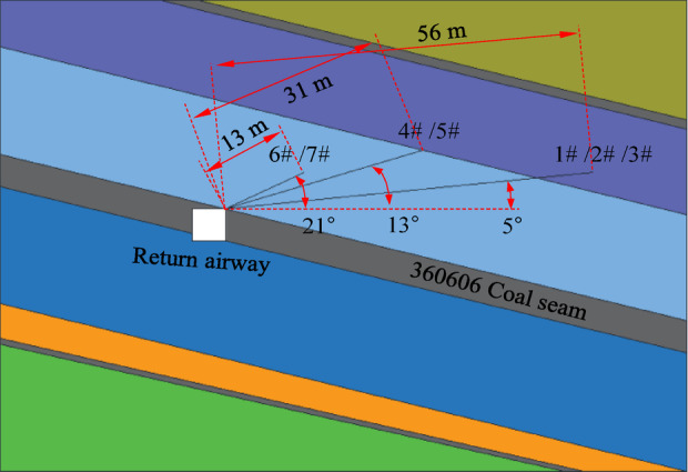
Layout of blast holes in the return airway of the 360,606 working face.
Table 4.
Pre-splitting blasting parameters for the roof of the 360,606 working face return airway.
| No | Drilling angle (°) | Drilling length (m) | Sealing length (m) | Charged length (m) | Charge amount (kg) |
|---|---|---|---|---|---|
| 1# | 5 | 56 | 18 | 38 | 125.4 |
| 2# | 5 | 56 | 18 | 38 | 125.4 |
| 3# | 5 | 56 | 18 | 38 | 125.4 |
| 4# | 13 | 31 | 10 | 21 | 69.3 |
| 5# | 13 | 31 | 10 | 21 | 69.3 |
| 6# | 21 | 13 | 4 | 9 | 29.7 |
| 7# | 21 | 13 | 4 | 9 | 29.7 |
Figure 11 and Table 5 show the pre-splitting blasting parameters for the roof of the 360,606 working face haulage roadway.
Fig. 11.

Layout of blast holes in the 360,606 working face haulage roadway.
Table 5.
Pre-splitting blasting parameters for the roof of the 360,606 working face haulage roadway.
| No | Drilling angle (°) | Drilling length (m) | Sealing length (m) | Charged length (m) | Charge amount (kg) |
|---|---|---|---|---|---|
| 1# | 27 | 51 | 17 | 34 | 112.2 |
| 2# | 22 | 54 | 16 | 38 | 125.4 |
| 3# | 22 | 54 | 16 | 38 | 125.4 |
| 4# | 18 | 58 | 20 | 38 | 125.4 |
| 5# | 18 | 58 | 20 | 38 | 125.4 |
| 6# | 22 | 24 | 8 | 16 | 52.8 |
| 7# | 22 | 24 | 8 | 16 | 52.8 |
Engineering site test
Drilling plan
According to the construction plan, several blasting holes are drilled in the blasting operation area. The YZJ column hydraulic rotary drilling rig is selected as the drilling rig (Table 6). Figure 12 shows the construction drawing of the cutting and drilling machine.
-
(2)
Charge structure
Table 6.
Parameters of the pre-splitting drilling machine.
| Machine model | YZJ column hydraulic rotary drilling rig |
|---|---|
| Drilling diameter (mm) | 60–103 |
| Drilling depth (m) | 150 |
| Propulsive force (kN) | 10 |
| Using lithology | f ≤ 12 |
| Motor power (kN) | 7.5 |
Fig. 12.
Construction site of the drilling rig.
A hydraulic drilling rig with a drilling diameter of 95 mm is used on site for the operation. A third-grade water gel explosive conforming to coal mine safety permit standards is selected. The specification of the explosive roll is 63 mm, with a charge column of 3.3 kg per m and a detonating cord inside the charge column. Figure 13 shows the physical image of the explosive.
Fig. 13.

Water-gel explosive.
The slotted tubes are interconnected via coupling components, which ensures connection strength and accommodates appropriate bending deformation. An anti-slip barbed structure is integrated at the joints to prevent tube slippage during borehole installation. Explosive assembly is integrally inserted into the borehole after surface charging in the roadway.
-
(3)
Sealing scheme
Mining silicate-modified polyurethane grouting reinforcement material is used to seal the hole. Component A is a white liquid with a density of 1.46 g/cm3 and a viscosity of 301 MPa.s; component B is a brown liquid with a density of 1.19 g/cm3 and a viscosity of 212 MPa.s. Both components are mixed at a ratio of 1:1 to form a white silicate-modified polyurethane material, which is specially used for the reinforcement of middling coal rock mass in coal mines. The highest reaction zone temperature is 97.1 °C, with the shear strength of 16 MPa, the compressive strength of 42 MPa, an expansion ratio of 1.01, the bonding strength of 3.4 MPa, the tensile strength of 7 MPa, the curing time of 136 s, and the liquid flow time of 10 s.
Grouting amount Q for sealing the hole is defined by
 |
24 |
Calculation parameters are as follows. db = 95 mm, ρA = 1.46 g/cm3, ρB = 1.19 g/cm3, and kp = 1.01. Q = 9.1 kg/m.
Figure 14 shows on-site hole sealing.
-
(4)
Blasting method
Fig. 14.

Blast hole sealing.
The detonators are electronic ones approved for use in coal mines. The electronic detonators and their wires shall withstand high temperatures above 120 °C. Each blast hole is equipped with two electronic detonators of the same section, connected in series with the blasting network. Three-stage micro differential blasting is used to prevent excessive energy concentration during single blasting and affect the roadway support.
Deformation of surrounding rocks in roadways and the effect of roof cutting
Roof delamination of the roadway
Four measuring stations are arranged in the 360,606 machine tunnel, with an interval of 40 m between each station. Five measuring stations are arranged in the 360,606 wind tunnel, with an interval of 40 m between each station. Monitoring includes the movement of the surrounding area of the tunnel, the separation of the roof stratum, the support pressure of the unit support in the tunnel, the axial force of the anchor rod, and force on the hydraulic support of the working face. The specific location of the monitoring points is arranged in the middle of the roadway. Figure 15 shows the station layout.
Fig. 15.

Layout of working face measurement stations for 6# coal seam.
A roof separation monitoring device is installed in each station alley to monitor roof separation. The monitoring depth of the roof separation instrument is 6 and 10 m for shallow and deep base points, respectively.
Figure 16 presents collected data on roof separation at stations 1 and 2 of the 360,606 working face. The displacements of the deep and shallow measurement points are about 22 and 25 mm, respectively. Comprehensive analysis shows that the roof separation is maintained within a reasonable range of about 22 mm. Anchor cables and bolts have controlled roof separation.
-
(2)
Surface displacement of the roadway
Fig. 16.

Displacement curves of abscission layer roof.
Surface displacement in the roadway is observed using the cross method. Figure 17 shows the station layout. Measuring point A1 at the center of roadway roof and measuring point A2 at the center of the floor are arranged to monitor the movement of roof and floor. Measurement point B1 at the center of the coal pillar support and measurement point B2 at the center of the mining support are set to monitor the proximity of the two supports.
Fig. 17.
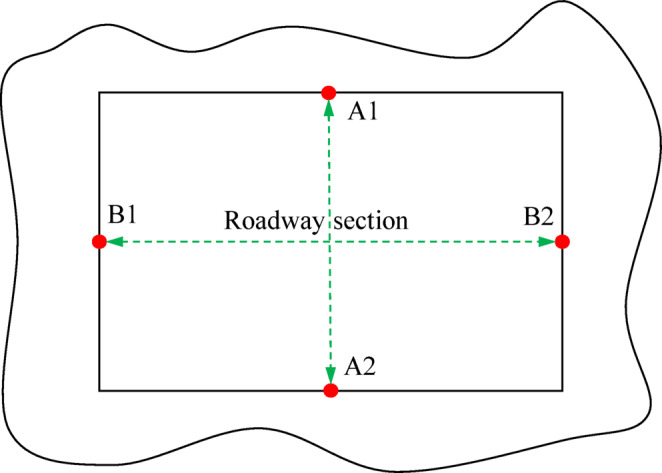
Layout of deformation measurement points for the surrounding rocks of the roadway.
Figure 18 shows the displacement changes of the surrounding rocks in the machine roadway of the 360,606 working face. Data from station 1 before and after mining are selected for comparative analysis. Surrounding rocks of the roadway undergo significant deformation during mining. When the working face advances to a distance of 40–100 m from the roadway, the deformation of the roadway gradually intensifies. When the working face advances to a distance of 40 m from the roadway, the deformation rate of surrounding rocks sharply increases. Follwoing the mining operation, the displacements of roof, coal pillar support, mining support, and floor were 238, 124, 100, and 48 mm, respectively. The pre-splitting and roof-cutting process has the following functions, e.g., cutting off the stress transmission path between roof and the goaf, reducing the length of hanging roof, redistributing the stress of roadway surrounding rocks, and improving the stability of roadway surrounding rocks.
-
(3)
Protection effect of roof cutting in roadways
Fig. 18.

Displacement variation law of roadway surrounding rocks during the mining period of 360,606 working face.
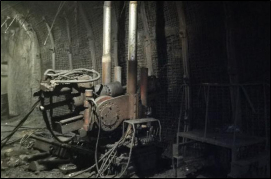
The photos of the return airway in the 360,606 working face were collected after adopting pre-splitting blasting to cut roof and relieve pressure to protect the roadway (Fig. 19).
Fig. 19.
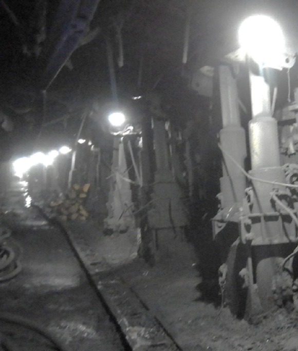
Gob-side entry retaining.
The implementation of pre-splitting, blasting, roof-cutting, and roadway retention technology in the 306,606 working face yielded the desired results, with the surrounding rock deformation within the roadway meeting engineering specifications. More coal pillars with a width of 10 m were mined in the reserved roadway section. This process increased the recovery rate and achieved the technical value of pre-splitting blasting for roof cutting and roadway protection.
Conclusion
Energy concentrated at the crack tip after the explosion. When accumulated energy at the crack tip exceeded the deformation energy of rocks, the crack further expanded. This process caused damage to rock mass and achieved blasting and roof cutting.
According to numerical simulation, a decoupling coefficient of 1.5 yielded the optimal distribution of blasting energy between the fracture and vibration zones, which prevented energy waste associated with excessive fragmentation. When the distance between blast holes was 5 m, the peak effective stress was 98.6 MPa at the midpoint of the blast hole connection. Based on the comprehensive analysis of the effective stress cloud map, the optimal blast hole distance was 5 m.
The displacements of roof, coal pillar support, mining support, and floor were 238, 124, 100, and 48 mm, respectively. Combined with the effect of the 306,606 working face return airway retention, the pre-splitting blasting roof-cutting technology can achieve roof-cutting and roadway protection.
Acknowledgements
Acknowledgements This study was supported by Anhui University of Science and Technology Scientific Research Start-up Fund for High-Level Talents(2023yjrc04), and the the National Natural Science Foundation of China (No. 52374075) .
Author contributions
Paper revision and polishing, Y. L. and G. C.; paper writing, Y. L., G. C., Di, and W.; literature research, G. C, Di, and W.. All authors have read and agreed to the published version of the manuscript.
Funding
(1) Anhui University of Science and Technology Scientific Research Start-up Fund for High-Level Talents(2023yjrc04), (2) National Natural Science Foundation of China (No. 52374075).
Data availability
Some or all data, models, or codes generated or used during the study are available from the corresponding authors by request.
Declarations
Competing interests
The authors declare no competing interests.
Consent to publish
All authors of this article consent to publish. All participant of this article provided the consent to publish.
Footnotes
Publisher’s note
Springer Nature remains neutral with regard to jurisdictional claims in published maps and institutional affiliations.
References
- 1.He, M. C. et al. Control of surrounding rock structure for gob-side entry retaining by cutting roof to release pressure and its engineering application. J. China Univ. Min. Technol.46(05), 959–969 (2017). [Google Scholar]
- 2.He, M. C. et al. Key parameters of the gob-side entry retaining formed by roof cutting and pressure release in deep medium-thickness coal seams. J. China Univ. Min. Technol.47(03), 468–477 (2018). [Google Scholar]
- 3.He, M. C. et al. Feature analysis of working face strata pressure with roof cutting pressure releasing in medium-thick seam and compound roof condition. Chin. J. Rock Mech. Eng.37(11), 2425–2434 (2018). [Google Scholar]
- 4.Chen, S. Y. et al. Determination of key parameters of gob-side entry retaining by cutting roof and its application to a deep mine. Rock Soil Mech.40(01), 332–342 (2019). [Google Scholar]
- 5.Chen, Y. et al. Study on the application of short-hole blasting with guide hole to roof cutting pressure relief of gob-side entry retaining. J. Min. Saf. Eng.32(02), 253–259 (2015). [Google Scholar]
- 6.Sun, X. M. et al. Key parameters oF gob-side entry retaining formed by roof cut and pressure releasing in thin coal seams. Chin. J. Rock Mech. Eng.33(07), 1449–1456 (2014). [Google Scholar]
- 7.Yuan, C. F. et al. Reasonable parameters of roof cutting entry retaining in thin immediate roof and large mining height fully-mechanized face. J. China Coal Soc.44(07), 1981–1990 (2019). [Google Scholar]
- 8.Guo, J. G. et al. Self-forming roadway of roof cutting and surrounding rock control technology under thick and hard basic roof. J. China Coal Soc.46(09), 2853–2864 (2021). [Google Scholar]
- 9.Huang, Z. Z. et al. Stress distribution of cutting roof with deep borehole blasting for gob-side entry retaining techonolgy. Coal Sci. Technol.50(S2), 88–96 (2022). [Google Scholar]
- 10.Hua, X. Z. et al. Floor heave mechanism of roadway retention with roof cutting in deep minesand its prevention and control. Rock Soil Mech.46(03), 955–968 (2025). [Google Scholar]
- 11.Hua, X. Z. et al. The deformation mechanism and zoning control technology of surrounding rocks of the roof-cutting deep well. J. Min. Saf. Eng.41(04), 655–665 (2024). [Google Scholar]
- 12.Hao, Q. et al. Optimisation of anti-impact parameters and engineering practice of pre-split blasting for hard-thick disastrous rock strata. J. Min. Saf. Eng.41(03), 481–492 (2024). [Google Scholar]
- 13.Qiao, G. D. et al. Experimental study on the control of mine pressure and gas gover- nance in thick and hard roof by pre-blasting of slotted cartridge. J. China Univ. Min. Technol.53(02), 334–345 (2024). [Google Scholar]
- 14.Li, Q. et al. Study on the most optimistic hole spacing for double-hole blasting under high in-situ stresses. Chin. J. Rock Mech. Eng.44(03), 678–690 (2025). [Google Scholar]
- 15.Zhao, Z. P., Yan, R. B. & Cong, J. Y. Advanced deep hole pre - splitting blasting of hard roof type and ef-fect evaluation analysis. Coal Sci. Technol.51(3), 68–76 (2023). [Google Scholar]
- 16.Cao, A. Y. et al. Crack extension mechanism of deep-hole blasting in the roof ofhigh-tectonic-stress region and its application. J. Min. Saf. Eng.42(01), 97–107 (2025). [Google Scholar]
- 17.Hu, Y. C. et al. Research on high-efficiency sealing material and techmology ofcoal roof deep-hole pre-splitting blasting. Coal Sci. Technol.51(4), 30–36 (2023). [Google Scholar]
- 18.Xie, J. H. et al. Rockburst prevention mechanism and effect test of blastpresplitting of hard roof in gob-side roadway. J. China Coal Soc.48(05), 2078–2091 (2023). [Google Scholar]
- 19.Zhao, S. K. Mechanism and application of force-structure cooperative prevention andcontrol on rockburst with deep hole roof pre-blasting. J. China Coal Soc.46(11), 3419–3432 (2021). [Google Scholar]
- 20.Xiao, T. Q. et al. Study on mechanism and technology of roof cutting and pressure relief in deep roadway with strong dynamic pressure and high gas. J. Min. Strata Control Eng.6(06), 130–144 (2024). [Google Scholar]
- 21.Liu, X. Study on roof stability and collaborative control of gob-side entry retaining by roof cutting in deep mine. (Anhui University of Science and Technology, 2020).
- 22.Hao, H. H. Research on key parameters and GroundPressure behavior law of roof cutting and entry retention in Zhuzhuang coal mine. (China University of Mining and Technology, 2023).
- 23.Zhang, Y. Research on deep hole pre-splitting blasting technology for fracture and permeability enhancement in low permeability coal seam. (Henan Polytechnic University, 2022).
Associated Data
This section collects any data citations, data availability statements, or supplementary materials included in this article.
Data Availability Statement
Some or all data, models, or codes generated or used during the study are available from the corresponding authors by request.