Abstract
We describe the first of two large-scale atomic simulation projects on materials failure performed on the 12-teraflop ASCI (Accelerated Strategic Computing Initiative) White computer at Lawrence Livermore National Laboratory. This is a multimillion-atom simulation study of crack propagation in rapid brittle fracture where the cracks travel faster than the speed of sound. Our finding centers on a bilayer solid that behaves under large strain like an interface crack between a soft (linear) material and a stiff (nonlinear) material. We verify that the crack behavior is dominated by the local (nonlinear) wave speeds, which can be in excess of the conventional sound speeds of a solid.
Molecular Dynamics (MD) Experiments on ASCI (Accelerated Strategic Computing Initiative) White Computer
During September of the new millennium, IBM delivered the world's fastest computer to the Lawrence Livermore National Laboratory. Scientific American calls it “the computer of tomorrow” (1). For the first 4 months, the ASCI White computer was tuned, and scientists from a variety of fields were privileged to play with it. We were some of the lucky players. An important goal of the Department of Energy materials science program is to gain better understandings of materials failure under extreme conditions. We accomplished two atomistic simulation projects. The first was a multimillion-atom simulation study of crack propagation in rapid brittle fracture, and the second investigated ductile failure by using over one billion atoms. What we accomplished in a frantic few months of intense effort will be described. We present a brief discussion about simulating the dynamics of many atoms by using big computers.
With the present-day supercomputers, simulation is becoming a very powerful tool for providing important insights into the nature of materials failure. Atomistic simulations yield ab initio information about materials deformation at length and time scales unattainable by experimental measurement and unpredictable by continuum elasticity theory. Using our “computational microscope,” we can see what is happening at the atomic scale. Our simulation tool is computational MD (2), and it is very easy to describe. MD predicts the motion of a large number of atoms governed by their mutual interatomic interaction, and it requires the numerical integration of the equations of motion, force equals mass times acceleration or F = ma. We learn in beginning physics that the dynamics of two atoms can be solved exactly. Beyond two atoms, this is impossible except for a few very special cases, and we must resort to numerical methods. A simulation study is defined by a model created to incorporate the important features of the physical system of interest. These features may be external forces, initial conditions, boundary conditions, and the choice of the interatomic force law.
In the present simulations, we adopt simple interatomic force laws because we want to investigate the generic features of a particular many-body problem common to a large class of real physical systems and not governed by the particular complexities of a unique molecular interaction. It is very important to emphasize that this is a conscious choice because it is not uncommon to hear others object that one is not studying “real” materials when using simple potentials. Feynman (3) summarized this viewpoint well on page 2, volume I of his famous three-volume series Feynman's Lectures In Physics:
“If in some cataclysm all scientific knowledge were to be destroyed and only one sentence passed on to the next generation of creatures, what statement would contain the most information in the fewest words? I believe it is the atomic hypothesis that all things are made of atoms—little particles that move around in perpetual motion, attracting each other when they are a little distance apart, but repelling upon being squeezed into one another. In that one sentence, you will see there is an enormous amount of information about the world, if just a little imagination and thinking are applied.”
A simple interatomic potential may be thought of as a “model potential,” and the model potentials for the present studies are harmonic and anharmonic springs and the Lennard-Jones (LJ) 12:6 potential. Complaints of model approximations are not new. In his book entitled The New Science of Strong Materials or Why Don't You Fall Through the Floor, Gordon (4) comments on Griffith's desire to have a simpler experimental material that would have an uncomplicated brittle fracture. He writes, “In those days, models were all very well in the wind tunnel for aerodynamic experiments but, damn it, who ever heard of a model material?”
In the mid-1960s, a few hundred atoms could be treated. In 1984, we reached 100,000 atoms. Before that time, computational scientists were concerned that the speed of scientific computers could not go much beyond 4 Gigaflops, or 4 billion arithmetic operations per second and that this plateau would be reached by the year 2000! That became forgotten history with the introduction of concurrent computing. A modern parallel computer is made up of several (tens, hundreds, or thousands) small computers working simultaneously on different portions of the same problem and sharing information by communicating with one another. The communication is done through message passing procedures. The present record is well over a few Teraflops for optimized performance, and we have now simulated over 1,000,000,000 atoms in a work-hardening study at the Lawrence Livermore National Laboratory by using the ASCI White 12-teraflop computer. Moore's Law states that computer speed doubles every 1½ years. For 35 years, that translates into a computer speed increase of 10 million. This is exactly the increase in the number of atoms that we could simulate over the last 35 years. For a visual description of ASCI White, we refer the reader to Scientific American's special issue entitled Extreme Engineering (1).
First Study: Supersonic Crack Propagation In Brittle Fracture
How Fast Can Cracks Move?
The first of our two simulation studies addressed the important question “how fast can cracks propagate?” In this study, we used system sizes of about 20 million atoms, very large by present-day standards but modest compared with our second study on ductile failure (23). Based on our current simulation model, we develop our earlier studies on transonic crack propagation in linear materials and supersonic crack propagation in nonlinear solids. Our finding centers on a bilayer solid that behaves under large strain like an interface crack between a soft (linear) material and a stiff (nonlinear) material. In this mixed case, we observe that the initial mother crack propagating at the Rayleigh sound speed gives birth to a transonic daughter crack. Then, quite unexpectedly, we observe the birth of a supersonic granddaughter crack. We verify that the crack behavior is dominated by the local (nonlinear) wave speeds, which can be in excess of the conventional sound speeds of a solid.
In this problem, there are three important wave speeds in the solid. In order of increasing magnitude, they are the Rayleigh wave speed, or the speed of sound on a solid surface, the shear (transverse) wave speed, and the longitudinal wave speed. Predictions of continuum mechanics (5, 6) suggest that a brittle crack cannot propagate faster than the Rayleigh wave speed. For a mode I (tensile) crack, the energy release rate vanishes for all crack velocities in excess of the Rayleigh wave speed, implying that the crack cannot propagate at a velocity greater than the Rayleigh wave speed. A mode II (shear) crack behaves similarly to a mode I crack in the subsonic velocity range; i.e., the energy release rate monotonically decreases to zero at the Rayleigh wave speed and remains zero between the Rayleigh and shear wave speeds. However, the predictions for the two loading modes differ for crack velocities greater than the shear wave speed. Whereas the energy release rate remains zero for a mode I crack, it is positive for a mode II crack over the entire range of intersonic velocities. From these theoretical solutions, it has been concluded that a mode I crack's limiting speed is clearly the Rayleigh speed. The same conclusion also has been suggested for a mode II crack's limiting speed because the “forbidden velocity zone” between the Rayleigh and shear wave speeds acts as an impenetrable barrier for the shear crack to go beyond the Rayleigh wave speed.
The first direct experimental observation of cracks moving faster than the shear wave speed has been reported by Rosakis et al. (7). They investigated shear dominated crack growth along weak planes in a brittle polyester resin under dynamic loading. Around the same time, we performed two-dimensional MD simulations of crack propagation along a weak interface joining two strong crystals (8). We assumed that the interatomic forces are harmonic except for those pairs of atoms with a separation cutting the centerline of the simulation slab. For these pairs, the interatomic potential is taken to be a simple model potential that allows the atomic bonds to break. Our simulations demonstrated intersonic crack propagation and the existence of a mother-daughter crack mechanism for a subsonic shear crack to jump over the forbidden velocity zone. We have since discovered that a crack cannot only travel supersonically (9) but a mother-daughter-granddaughter crack mechanism exists in bilayer slabs.
The classical theories of fracture (5, 6) are largely based on linear elastic solutions to the stress fields near cracks. An implicit assumption in such theories is that the dynamic behavior of cracks is determined by the linear elastic properties of a material. We have found (10) that the MD simulation results for harmonic atomic forces are indeed well interpreted by elasticity theories. However, the effects of anharmonic material properties on dynamic behaviors of cracks are not clearly understood. This is partly because of the general difficulties in obtaining nonlinear elastic solutions to dynamic crack problems. MD simulations can be easily adapted to the anharmonic case so that nonlinear effects can be thoroughly investigated. We now discuss the anharmonic simulations.
The Computer Experiments Setup.
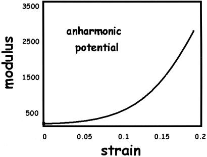
We consider a strongly nonlinear elastic solid described by a tethered LJ potential where the compressive part of this potential is identical to that of the usual LJ 12:6 function and the tensile part is the reflection of the compressive part with respect to the potential minimum. A face-center-cubic (FCC) crystal formed by this potential exhibits a strongly nonlinear stress-strain behavior resulting in elastic stiffening and an increase of the elastic modulus with strain, as shown in Fig. 1. Note that the elastic modulus increases by a factor of 10 at 13% of elastic strain, indicating that the material properties of such a solid is strongly nonlinear in the hyperelastic regime.
Figure 1.
Variation of elastic modulus as a function of strain under uniaxial stretching in the (110) direction of a FCC crystal formed by the anharmonic (tethered repulsive LJ) potential.
We performed three-dimensional MD simulations of two FCC crystals joined by a weak interface. In this study, we used system sizes of about 20 million atoms, although a billion atoms were used in a preliminary simulation (9). For comparison, we consider the anharmonic tethered potential together with the harmonic potential where the spring constant is equal to the tethered potential at equilibrium. The interatomic force bonding the two crystals is given by the LJ 12:6 potential. The simulation results are expressed in reduced units: lengths are scaled by the value of the interatomic separation where the LJ potential is zero and energies are scaled by the depth of the minimum of the LJ potential. Atoms bond only with their original nearest neighbors. Hence, rebonding of displaced atoms caused by applied loading does not occur. For the adjoining two crystal slabs, we consider the following three simulation cases: (i) harmonic case—both crystal slabs are characterized by the harmonic potential; this is used as a control for the anharmonic studies; (ii) anharmonic case—both crystal slabs are characterized by the anharmonic potential; and (iii) mixed case—one crystal slab is characterized by the anharmonic potential, and the other is characterized by the harmonic potential. In each case, a shear crack lies along the (110) plane and oriented toward the [110] direction. The crack front is parallel to the (001) direction. The applied loading is dominated by shear.
To interpret the results of MD simulation, we need the following wave speeds in the FCC crystals formed by harmonic and/or anharmonic potentials: the conventional longitudinal and shear wave speeds in the harmonic and anharmonic crystals in the direction of crack propagation; the longitudinal and shear wave speeds under applied loading in the anharmonic crystal in the direction of crack propagation; and the local longitudinal and shear wave speeds near the crack tip in the anharmonic crystal in the direction of crack propagation. The calculations of these wave speeds will be presented in detail in a forthcoming paper. We give the results in Table 1.
Table 1.
Calculated wave speeds for the harmonic wave speeds, bulk anharmonic wave speeds caused by applied loading, and local wave speeds
| Bulk harmonic | Bulk anharmonic | Local | |
|---|---|---|---|
| Longitudinal wave | 9.49 | 10.36 | 13.4 |
| Shear wave | 4.24 | 5.95 | 10.4 |
We add some comments with regard to the concept of local wave speeds near the crack tip, which play a critically important role in explaining our simulation results. Conceptually, it is clear that the fracture process in brittle solids involves breaking of atomic bonds and is intrinsically a highly nonlinear process. The anharmonic material properties of solids near the cohesive strength of atomic bonds would in general be quite different from the harmonic properties. In an earlier attempt to explain why the highest crack velocities recorded for mode I crack propagation in a homogeneous body are significantly lower than the Rayleigh wave speed, Broberg (5, 6, 11) has suggested that the reason could be because of some kind of a “local” Rayleigh wave speed in the highly strained region near the crack tip, rather than the Rayleigh wave speed in the undisturbed material. Because the local strain is an extremely strong function of position from the crack tip, one might think that the local wave speed should depend on distance from the crack tip and cannot have one single value. It was not until 30 years after Broberg's suggestion that this issue was finally quantitatively studied by Gao (12, 13) who made use of the Barenblatt cohesive model of a mode I crack and, for the first time, defined the local wave speed unambiguously as the wave speed at the location where stress is exactly equal to the cohesive strength of the material, i.e., the true point of fracture nucleation. The local wave speed characterizes how fast elastic energy is transported near the region of bond breaking in front of a crack tip. For example, for a mode I crack in a homogeneous isotropic elastic, the local wave speed is calculated to be  (12, 13), where σmax is the cohesive strength and ρ is the density of the undisturbed materials. The cohesive strength is typically around 1/10 of the shear modulus, suggesting that the local wave speed for a mode I crack is ≈1/3 of the shear wave speed. Interestingly, experiments (14, 15) and MD simulations (16, 17) show that mode I cracks exhibit a dynamic instability at 30% of the shear wave speed, which suggests a possible dependence on the local wave speed (12, 13). We note that the local wave speeds differ from the conventional wave speeds both qualitatively and quantitatively.
In the present study, the focus is shifted to study the effect of stiffening anharmonic behaviors of materials (as in many polymers) on a mode II crack propagating along a weak interface described by the LJ potential. The solid itself is described by the tethered LJ potential. We follow the same approach used in refs. 12 and 13 and define the local wave speed as the wave speed of the solid at the location adjacent to the interface where the shear stress is exactly equal to the cohesive strength of the interface. Note that in this case the local wave speed depends on both the interface cohesive strength and the nonlinear elastic properties of the solid.
The Computer Experiments Results and Discussion.
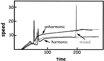
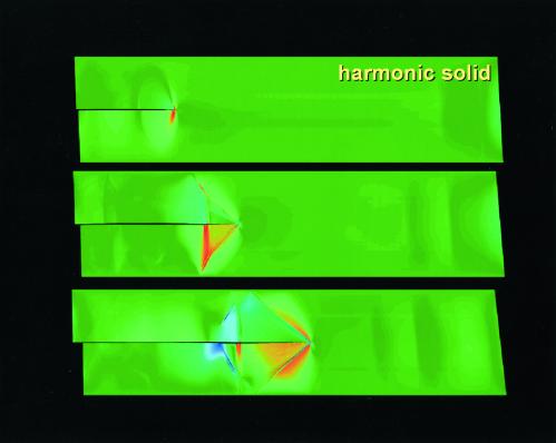
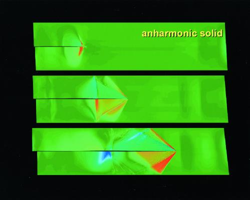
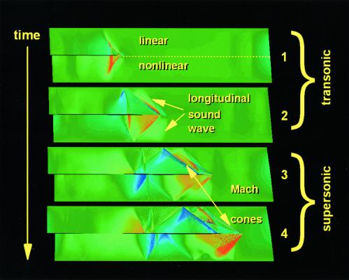
Fig. 2 presents distance-time histories of a crack moving in the three different slab configurations: two weakly bonded harmonic crystals (designated harmonic), two weakly bonded anharmonic crystals (designated anharmonic), and a harmonic crystal weakly bonded to an anharmonic crystal (designated mixed). The cracks begin their motion when the Griffith criterion is satisfied. The respective dip-spike regions for each history represent the birth of a new crack. For the harmonic and anharmonic simulations (see Figs. 3 and 4), we observe one such region representing the birth of a daughter crack, the former traveling at the longitudinal sound speed for the harmonic solid and the latter achieving a supersonic sound speed of Mach 1.6. For the mixed simulation (see Fig. 5), we see two such dip-spike regions where a daughter crack is born from the mother crack, which then gives birth to a granddaughter crack at a later time.
Figure 2.
The space-time history of the crack tip for the three different simulations described in the text (reduced units are used).
Figure 3.
Snapshot pictures of a crack traveling in the harmonic slab, where the progression in time is from the top to the bottom. The boxed snapshot pictures represent a progression in time from the top to the bottom.
Figure 4.
Snapshot pictures of a crack traveling in the anharmonic slab, where the progression in time is from the top to the bottom. The boxed snapshot pictures represent a progression in time from the top to the bottom.
Figure 5.
Snapshot pictures of a crack traveling in the mixed slab, where the progression in time is from the top to the bottom. The sound waves associated with the crack's dynamics and the material properties of the harmonic and anharmonic regions of the mixed slab are labeled.
In Figs. 3 and 4, the harmonic and anharmonic simulations are shown, respectively. The boxed snapshot pictures in each figure represent a progression in time from the top to bottom. In the top images, the mode II daughter cracks are born. The early-time occurrence of the Mach cone attached to the crack tip is evident in the anharmonic slab; in the middle image of Fig. 3, the crack in the harmonic slab has a single Mach cone and a circular stress-wave halo, which indicates a crack speed equal to the longitudinal sound speed of the linear solid. This is in contrast to the middle image of Fig. 4 where the two Mach cones for the crack in the anharmonic slab signify that the crack is traveling supersonically. For the bottom images of the two figures, we conclude that the crack in the anharmonic slab wins.
In Fig. 5, snapshot pictures of the crack traveling in the mixed slab are presented, where the progression in time is from the top to bottom. The material properties for the harmonic and anharmonic regions are labeled, and the different sound waves associated with the crack's dynamics are denoted. The sequence shows the following progression of events: (i) the daughter crack is born; (ii) the daughter crack is traveling at the longitudinal sound speed of the harmonic slab; (iii) the granddaughter crack is born; and (iv) the granddaughter crack speeds ahead to Mach 1.6, matching the crack speed in the anharmonic slab (movies of the brittle fraction simulations may be viewed and downloaded at http://www.almaden.ibm.com/st/Simulate).
We have shown that the behavior of the crack in the harmonic crystal is controlled by the conventional elastic wave speeds (6). In contrast, the crack behavior in the anharmonic crystal is controlled by the local wave speeds, which play an important role in the dynamic behavior of crack propagation. A similar dependence has been identified in a related phenomenon where hyperelasticity plays an important role in whether a solid will undergo brittle fracture or ductile failure at the crack tip (18, 19). The local wave speed represents the nonlinear, hyperelastic, material properties near cohesive failure of atomic bonds while the conventional elastic (shear and longitudinal) wave speeds represent the material properties under infinitesimal deformation and can differ significantly from the harmonic wave speeds. The crack propagation speeds observed in MD simulations are tabulated in Table 2 for comparison.
Table 2.
Observed speeds at which a daughter crack or a granddaughter crack nucleates and the limiting speeds for the harmonic, anharmonic, and mixed simulation cases
| Harmonic | Anharmonic | Mixed | |
|---|---|---|---|
| Daughter crack | 3.5 | 4.1 | 4.1 |
| Granddaughter | — | — | 10.35 |
| Limiting speed | 9.4 | 15 | 15 |
Comparing the MD simulation results with the calculated wave speeds for harmonic and anharmonic crystals, we reach the following conclusions.
The harmonic case is consistent with the linear elastic theory of intersonic crack propagation. We have previously discussed this case in detail for two-dimensional harmonic MD simulation (8). The same theory is found to apply for the present three-dimensional case. Essentially, the initial crack starts to propagate when the Griffith criterion is satisfied. Near the Rayleigh wave speed, the crack encounters a velocity barrier and a vanishing of stress singularity at the crack tip; i.e., both stress intensity factor and energy release rate vanish at the Rayleigh wave speed. This velocity barrier is overcome by the nucleation of a daughter crack at a distance ahead of the mother crack. This distance corresponds to the shear wave front at which a peak of shear stress increases to a critical magnitude to cause cohesive failure of the interface. The daughter crack's speed is only limited by the longitudinal wave speed. Comparing Tables 1 and 2, we see that the daughter crack indeed nucleates at the Rayleigh wave speed and the limiting speed agrees very well with the longitudinal wave speed for the harmonic crystal. The mother-daughter mechanism described above is consistent with the Burridge-Andrew model of intersonic crack propagation (20, 21).
In the anharmonic case, the nucleation of the daughter crack is consistent with linear elastic theory. The mother crack initiates according to the Griffith criterion and achieves a limiting velocity equal to the Rayleigh wave speed. At this point, it is necessary to nucleate a daughter crack to break the velocity barrier. The limiting speed of the daughter crack is more than 50% higher than the longitudinal wave speed and cannot be explained by the linear theory of intersonic fracture. In comparison, the calculated local wave speed is approximately equal to (only 10% lower than) the observed limiting speed. In calculating the local wave speeds, we have ignored the large gradient of deformation field near the crack tip. In view of this simplification, we conclude that the local wave speed provides a reasonable explanation of the observed limited crack speed.
In the mixed case, the nucleation of the daughter crack still occurs at the Rayleigh wave speed for reasons discussed above. The daughter crack breaks the velocity barrier at the Rayleigh speed and propagates near the longitudinal wave speed. This behavior is similar to the harmonic case. However, at a velocity of 10.35, we observe a granddaughter crack forming ahead of the daughter crack. The critical speed at which this transition occurs is very close to the local shear wave speed in the anharmonic crystal. The granddaughter crack rapidly accelerates toward the local longitudinal wave speed of the stretched nonlinear solid. It is tempting to conclude that the nucleation of the granddaughter crack is controlled by the local Rayleigh wave speed magnified by the local stress concentration, although this issue is worth further investigation.
In summary, we conclude that the local wave speeds play a dominant role in the behavior of cracks in the anharmonic crystals. The mixed case behaves somewhat like an interface crack between a soft material and a stiff material. Although the harmonic and anharmonic crystals have identical material properties under infinitesimal deformation, the local material properties near the crack tip are resembled by a bimaterial. Rosakis et al. (22) have previously studied crack propagation along an interface between polymethyl/methacrylate (PMMA) (soft) and Al (hard) and found that the crack speed can significantly exceed the longitudinal wave speed of PMMA. Our present study shows that the crack behavior is dominated by the local (nonlinear) wave speeds. This is not only of theoretical interest, but also of practical importance. It is known that many polymeric materials, especially rubbers, increase their modulus significantly when stretched. The underlying physical mechanism is that initial elasticity in rubbers is caused by entropic effects. When stretched to large deformation, the polymeric chains are straightened and covalent atomic bonds eventually dominate their hyperelastic response. In such solids, the elastic modulus increases with strain and the local wave speeds near a crack tip would be larger than the linear elastic wave speeds. The dynamic behavior of cracks in such solids should propagate at a speed exceeding the conventional wave speeds.
Another point worth commenting on here is the remarkable success of continuum theories in predicting the behaviors obtained by atomistic simulations. We have found previously (10) that the MD simulation results for shear crack propagation along a weak interface in harmonic solids are well interpreted by elasticity theories. In particular, calculations based on linear elasticity were able to predict the time and location of the daughter crack as well as the initiation time of the mother crack. Our atomistic simulation of the mother-daughter crack mechanism for intersonic shear crack is consistent with the continuum mechanics-based discovery made earlier by Burridge (20) and Andrews (21). An important message of the present study is that the nonlinear continuum theory of local wave speeds is capable of predicting crack velocities in strongly nonlinear solids. Indeed, it is quite remarkable that the dynamic behavior of cracks may retain its basic nature over such a wide range of length scales, from atomistic calculations by using interatomic potentials all of the way up to macroscopic laboratory experiments and continuum elasticity treatments. This bridging of length scales in dynamic materials failure should be of great interest to the general scientific audience because it points out the fantastic power of continuum mechanics.
Acknowledgments
F.F.A. acknowledges the essential contributions of Brian Wirth and the Lawrence Livermore National Laboratory ASCI White team under the guidance of Steve Louis and Terry Heidelberg. F.F.A. is indebted to Charles Rettner at the IBM Almaden Research Center for creating the web pages related to this paper. The work of H.G. is supported by National Science Foundation Grant CMS-9820988 and the Max Planck Society.
Abbreviations
- ASCI
Accelerated Strategic Computing Initiative
- MD
molecular dynamics
- FCC
face-center-cubic
- LJ
Lennard-Jones
References
- 1.Gibbs W. Sci Am Extreme Engineering. 1999;10:56–61. [Google Scholar]
- 2.Allen M P, Tildesley D J. Computer Simulation of Liquids. Oxford: Clarendon; 1987. [Google Scholar]
- 3.Feynman R, Leighton R, Sands M. The Feynman Lectures on Physics. Redwood City, CA: Addison–Wesley; 1963. [Google Scholar]
- 4.Gordon J E. The New Science Of Strong Materials or Why You Don't Fall Though the Floor. Princeton: Princeton Univ. Press; 1988. [Google Scholar]
- 5.Freund L B. Dynamical Fracture Mechanics. New York: Cambridge Univ. Press; 1990. [Google Scholar]
- 6.Broberg B. Cracks and Fracture. San Diego: Academic; 1999. [Google Scholar]
- 7.Rosakis A J, Samudrala O, Coker D. Science. 1999;284:1337–1340. doi: 10.1126/science.284.5418.1337. [DOI] [PubMed] [Google Scholar]
- 8.Abraham F F, Gao H. Phys Rev Lett. 2000;84:3113–3116. doi: 10.1103/PhysRevLett.84.3113. [DOI] [PubMed] [Google Scholar]
- 9.Abraham F F. J Mech Phys Solids. 2001;49:2095–2111. [Google Scholar]
- 10.Gao H, Huang Y, Abraham F F. J Mech Phys Solids. 2001;49:2113–2132. [Google Scholar]
- 11.Broberg B J. J Appl Mech. 1964;31:546–547. [Google Scholar]
- 12.Gao H. J Mech Phys Solids. 1996;4:1453–1474. [Google Scholar]
- 13.Gao H. Philos Mag Lett. 1997;76:307–314. [Google Scholar]
- 14.Fineberg J, Gross S P, Marder M, Swinney H L. Phys Rev Lett. 1991;67:457–460. doi: 10.1103/PhysRevLett.67.457. [DOI] [PubMed] [Google Scholar]
- 15.Fineberg J, Gross S P, Marder M, Swinney H L. Phys Rev B. 1992;45:5146–5154. doi: 10.1103/physrevb.45.5146. [DOI] [PubMed] [Google Scholar]
- 16.Abraham F F, Brodbeck D, Rafey R, Rudge W E. Phys Rev Lett. 1994;73:272–275. doi: 10.1103/PhysRevLett.73.272. [DOI] [PubMed] [Google Scholar]
- 17.Abraham F F, Brodbeck D, Rafey R, Rudge W E. J Mech Phys Solids. 1997;5:1595–1605. [Google Scholar]
- 18.Abraham F F. Phys Rev Lett. 1996;7:869–872. doi: 10.1103/PhysRevLett.77.869. [DOI] [PubMed] [Google Scholar]
- 19.Abraham F F, Schneider D, Land B, Lifka D, Skovira J, Gerner J, Rosenkrantz M. J Mech Phys Solids. 1997;45:1461–1471. [Google Scholar]
- 20.Burridge R. Geophys J R Astron Soc. 1973;35:439–455. [Google Scholar]
- 21.Andrews D J. J Geophys Res. 1976;81:5679–5687. [Google Scholar]
- 22.Rosakis A J, Samudrala O, Singh R P, Shukla A. J Mech Phys Solids. 1998;6:1789–1813. [Google Scholar]
- 23.Abraham F F, Walkup R, Gao H, Duchaineau M, Diaz De La Rubia T, Seager M. Proc Natl Acad Sci USA. 2002;99:5783–5787. doi: 10.1073/pnas.062054999. [DOI] [PMC free article] [PubMed] [Google Scholar]


