Abstract
The pathway of the gating conformational transition of Escherichia coli mechanosensitive channel was simulated, using the recently modeled open and closed structures, by targeted molecular dynamics method. The transition can be roughly viewed as a four-stage process. The initial motion under a lower tension load is predominantly elastic deformation. The opening of the inner hydrophobic pore on a higher tension load takes place after the major expansion of the outer channel dimension. The hypothetical N-terminal S1 helical bundle has been confirmed to form the hydrophobic gate, together with the M1 helices. The sequential breaking of the tandem hydrophobic constrictions on the M1 and S1 helices makes the two parts of the gate strictly coupled, acting as a single gate. The simulation also revealed that there is no significant energetic coupling between the inner S1 bundle and the outer M2 transmembrane helices. The molten-globular-like structural features of the S1 bundle in its intermediate open states may account for the observed multiple subconductance states. Moreover, the intermediate open states of mechanosensitive channels are not symmetric, i.e., the opening does not follow iris-like motion, which sharply contrasts to the potassium channel KcsA.
Keywords: targeted molecular dynamics‖change‖transition pathway‖ mechanotransduction‖ion channel‖gating mechanism
Mechanosensitive (MS) channels, also known as stretch sensitive channels, belong to a special class of membrane proteins that can transduce mechanical strains from touch, sound, pressure and gravity into electrochemical responses (1–5). In Mycobacterium tuberculosis (TbMscL) and Escherichia coli (EcoMscL), MS channels facilitate permeation of small osmolytes from the cytoplasm to the extracellular space, therefore permit a rapid regulation of turgor pressure.
MS channels are gated channels that stay in the closed state and open up when there is a tension in the cell membrane (6–14). The only available crystal structure is that of TbMscL (15), which is a homopentamer, with each monomer composed of a transmembrane domain and a cytoplasmic domain. The current structure represents the closed state, and obviously, conformational changes must occur to coordinate the opening of the channel (5, 15).
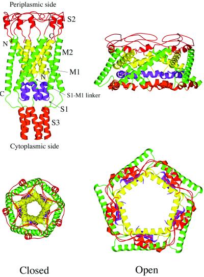
Significant efforts have been devoted to the understanding of the gating mechanisms of MscL (2, 4, 5, 16, 17). In recent combined experimental and modeling studies (18, 19), the closed, open, and intermediate structures of TbMscL and EcoMscL have been proposed. They were established by combining the x-ray structure of TbMscL, sequence consensus and the experimental data. In the modeled EcoMscL structures (Fig. 1), the main features are similar to those of the crystallographically resolved TbMscL structure, but there are certain noticeable modifications. The main torso of EcoMscL is formed by the transmembrane helices M1 and M2 from five identical subunits. The M1 helices form an inner bundle, and the M2 helices form a peripheral skirt that presumably contacts the lipid molecules in membrane. An important hypothetical structural element in the modeled EcoMscL is the N-terminal S1 helical bundle, whose critical role in gating has been proposed based on experimental studies (19). The S1 helices are connected to the M1 helices via an S1–M1 linker formed by three strictly conserved residues, Arg-13, Gly-14, and Asn-15. Finally, the C-terminal S3 helical bundle is located at the cytoplasmic bottom of the channel, which has been shown to be dispensable (8). At the periplasmic side, the S2 loops that connect the M1 and M2 helices in each subunit form the rim of the channel.
Figure 1.
Overall architecture of modeled EcoMscL. Both the closed (Left) and open (Right) forms are shown in side view (Upper) and top view (Lower). Major secondary structural elements are color-coded: yellow for M1, green for M2, blue for S1, red for S2, and orange for S3. The figures are made by graphic software MOLSCRIPT (28) and rendered by RASTE3D (29).
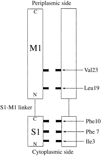
In the models (19), the existence of two gates has been proposed (Fig. 2). The first gate is formed by two layers of hydrophobic residues, Val-23 and Leu-19 from the periplasmic to cytoplasmic side, on the inner surface of the M1 helices and was suggested to act like a tension sensor. The second gate is formed by three layers of hydrophobic residues, Phe-10, Phe-7, and Ile-3, on the highly conserved N-terminal amphipathic S1 helices and was proposed to be the activation gate. The S1–M1 linker, whose length and sequence are strictly conserved in all 35 known MscL homologues, was also predicted to be crucial for the gating. The modeling study (19) proposed that the opening of EcoMscL is a two-step process. The first step, which is highly tension-dependent, involves the enlargement of the outer dimension of the channel with no significant increase of the size of the inner pore. The second one, which is relatively tension-independent, is a fast rupturing of the inner pore with no significant increase of the overall outer channel dimension. It also suggested that the first step corresponds to the opening of the first gate and accounts for two-thirds of the expansion of the outer dimension, and the second step corresponds to the opening of the second gate. In addition, the observed multiple subconductance states reflect the effective size of the channel pore, i.e., the openness of the gate (19).
Figure 2.
Schematic illustration of the tandem layers of hydrophobic lining of the gate that form the hydrophobic constrictions of the inner pore of the channel. For clarity, only two subunits are shown, and the M1 helices are drawn in parallel although they are packed at an angle in real structure. All other structural elements are omitted.
Although insights into the gating mechanism have been obtained from the modeling study (19), many problems remain unsolved, especially those regarding the order of the conformational changes during the gating process and the energetic coupling among various structural components. In this study, the gating conformational transition of EcoMscL from the predicted closed to open form is simulated by the targeted molecular dynamics (TMD) method (20), which has been shown to be highly successful in modeling large-scale conformational changes (21, 22). Although the time scale of transition in TMD simulation is not relevant to the realistic situation, the relative order of events in the conformational changes is determined by the intrinsic energy surface of the system. From the previous studies (21, 22), it is clear that the method can deliver reliable structural features along the transition pathways. Moreover, the TMD method is particularly suited for studying MscL because the conformational transition in TMD is facilitated by a weak time-dependent “pulling” force to guide the system toward the target state, which, to some extent, mimics the tension in the cell membrane that initiates the gate opening. Moreover, that “pulling” force is applied globally with little local bias, therefore, the order of events in the simulated conformational transition solely depends on the intrinsic energetics of the structure. Here, EcoMscL was simulated by the TMD method because most of the relevant experimental data have been obtained for this channel and the modeled structures (18, 19) are also publicly available. Although the originally modeled open and closed structures of EcoMscL may contain large errors at the atomic scale, their overall features are very likely to be correct as confirmed by the crosslinking experiments (18). This simulation was performed without the use of the predicted intermediate structures (19).
The results reported here reveal the order of events in the dynamic conformational transition. This order provides a more reliable spatial and temporal framework for interpreting the experimental data and for a deeper understanding of the gating mechanism of EcoMscL.
Methods
The detailed procedure of TMD simulation can be found in the original paper (20) and in several recent applications (21, 22). The coordinates of the open and closed EcoMscL were taken from (18). The charmm package (23) was used for simulation and the PARAM19 parameter was used for potential function (24). A modified TIP3P water model (24, 25) was used for water molecules. The shake algorithm (26) was used to constrain the lengths of bonds involving hydrogen atoms. The time step used for integration was 1.0 fs. A distance-dependent dielectric constant (23) was used to account for the insufficient electric screening caused by the relatively thin water shell of the system.
The simulation system contains a protein (665 amino acid residues) and 867 water molecules distributed as a solvation shell around the protein. Both end-point structures were carefully equilibrated to minimize the errors contained in the modeled structures. Repeated short simulation runs were made with portions of the structure (such as main chains and side chains) anchored by weak harmonic forces; the strength of the anchors was gradually diminished to zero toward the end of the equilibration. The structures were stable during the initial equilibration. At the end of the equilibrium, the water molecules predominantly moved to the vicinity of hydrophilic side chains. In the final production run, the conformational transition was achieved by a 500-ps targeted simulation. A longer simulation did not give qualitatively different results.
Results and Discussion
Overall Features of the Conformational Transition.
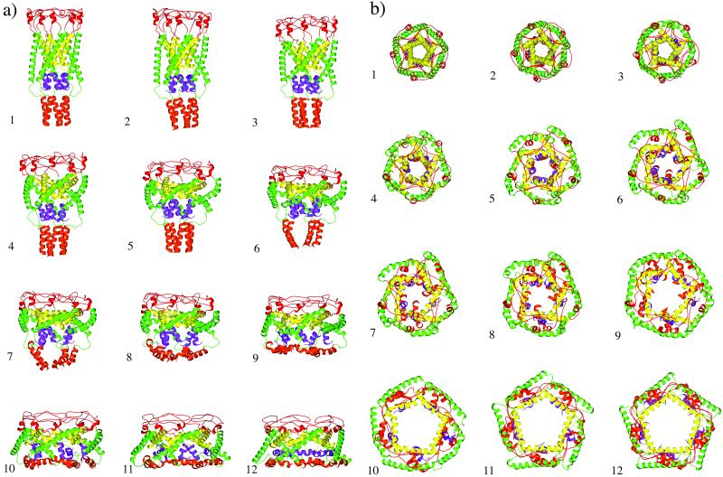
The simulated conformational transition of EcoMscL from the closed to open state is shown in Fig. 3. Although the transition took place continuously, the overall gating process can be roughly divided into four stages.
Figure 3.
Conformational transition pathway determined by TMD method, side view (a) and top view (b). The snapshots are chosen at equal time intervals, except 7, which is a half-interval insertion (also see the x axis of Fig. 5). Snapshots 1 and 12 are modeled structures in the closed and open forms, respectively.
The gating begins with a stage in which the height of the channel is significantly shortened in the vertical direction (1 to 5 in Fig. 3a) as a result of the motion of the transmembrane helices, especially the tilting and flattening of the inner M1 helices. At the periplasmic side of the channel, the C terminus of M1 and N terminus of M2 both move outward. Each M1 helix pivots around the bundle point located near the hydrophobic constriction formed by the rings of highly conserved Leu-19 and Val-23. As a result, the diameter of the channel, especially that of the periplasmic rim formed by the S2 loops, increases significantly. Strikingly, at the end of this stage, the vertical height of the inner M1 helical bundle is nearly the same as that in the final open state (compare the yellow portion in 1, 5, and 12 in Fig. 3a). But the hydrophobic constriction at Leu-19 and Val-23 is not open yet. The S1 and S3 helical domains remain intact, but they move somewhat into the membrane. No significant conformational change was observed in the S1–M1 linker region, although the angles between the S1 and M1 helices were changed. This initial phase of motion indicates that the channel is highly flexible, or elastic, with respect to the tilting of transmembrane helices, especially the shortening of the M1 helical bundle. It is, therefore, reasonable to conclude that this phase should indeed be the first response of the channel under a weak or moderate membrane tension.
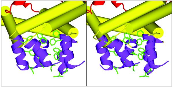
The second stage involves the outward expansion of the lower C termini of the M2 helices, partial opening of the hydrophobic constriction in the inner M1 bundle, and also a partial opening of the S1 bundle (5 to 7 in Fig. 3). Here the opening of the hydrophobic constriction in the M1 bundle, which requires a horizontal outward expansion of the lower N termini of the M1 helices, significantly precedes the opening of the S1 bundle. Toward the end of this stage, the cytoplasmic S3 bundle is also partially opened. A striking feature is that the opening of the S1 helical bundle is neither concerted nor symmetric, as exemplified in 6, 7, and 8 in Fig. 3b. This feature sharply contrasts to the iris-like concerted motion observed in the gating process of KcsA (27). In EcoMscL, the partially open S1 bundle behaves more like in a “molten globular” state. Therefore, their dissociation and reassociation during the intermediate stages of channel opening may account for the measured multiple subconductance states (18). The interactions between the S1 helices are predominantly hydrophobic from the aromatic side chains but with some electrostatic interactions as well (Fig. 4 and later).
Figure 4.
Stereo pair for the representative molten-globular state of the S1 helical bundle. The side chains of Ile-3, Phe-7, and Phe-10 are explicitly shown.
The third stage involves the complete opening of the hydrophobic constriction in the M1 bundle and a further but slower opening of the S1 bundle (7 to 11 in Fig. 3). The S3 bundle is also dramatically expanded, and all of the S3 helices end up horizontal at the cytoplasmic bottom of the channel. The opening of the M1 bundle is closely coupled to the opening of the S1 gate, though the former precedes the latter.
The last stage of the conformational change is a flip of the S1–M1 linker from the compact left-handed conformation to an extended right-handed conformation (11 to 12 in Fig. 3). It is in this stage that the S1 helices complete their docking to the inner wall of the channel. This particular feature seems to be reasonable. Assuming that the previous modeling study (19) has correctly predicted that the structure of the S1 segment is a helical bundle in the closed state and that each S1 helix is roughly parallel to the central axis of the channel, then it is also reasonable that, in the intermediate open structures, the S1 helices remain in a similar direction. Thus, they can reassociate to close the gate or lead to lower subconductance substates. Accordingly, the flip of the S1–M1 linker, if indeed it occurs, must occur after the opening of the last subconductance state.
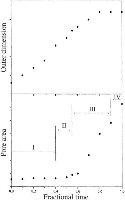
The time dependence of the outer channel dimension and the inner pore during the gating conformational change is shown in Fig. 5. The outer channel dimension enlarges quickly and continuously during the first 70% of the transition, and then levels off. In contrast, the inner pore area does not change appreciably during the first 60% of the transition (during which the outer channel dimension increases by about two-thirds) and then presents a sharp increase, corresponding to a sudden rupture of the pore. Therefore, it is very clear that the major opening of the inner pore takes place essentially after the outer channel reaches the fully open dimension. This feature is in accord with the conclusion from the previous modeling studies (18, 19) and the electrophysiological measurements (6).
Figure 5.
Time dependence of the outer channel dimension (Upper) and the inner pore area (Lower). The points are related to the snapshots in Fig. 3. The time is shown as fractions of the transition process. The units of y axes are somewhat arbitrary, and the curves are meant to show the qualitative tendency and relative scale of the change. The four stages (I to IV) of the gating process are approximately indicated in Lower (see main text).
Side-Chain Interactions Along the Transition Pathway.
Both hydrophobic and hydrophilic interactions were observed along the transition pathway. Because the conformations of hydrophilic side chains, especially the ionic ones, are much more difficult to predict accurately, large errors are inevitable in the modeled structures (18, 19). Therefore, we discuss the hydrophilic interactions with great caution.
It is known that hydrophobic interactions play an important role in the gating mechanism of McsL (5, 15, 18, 19). During the simulated transition, gradually from the periplasmic side to the cytoplasmic side, a sequential opening of the layers of the hydrophobic constrictions was observed (Fig. 2). The first layer that opens up is the one formed by Val-23, which is then followed by the layer formed by Leu-19. These two layers are the main hydrophobic barriers in the inner M1 helical bundle. Then, the horizontal outward expansion of the N termini of the M1 helices, via the S1–M1 linker, leads to the opening of the S1 helical bundle. The three hydrophobic layers in the S1 bundle open sequentially as well, first the Phe-10 layer, then the Phe-7 layer, and eventually the Ile-3 layer. The observed sequence of opening is consistent with the experimental observation that the cysteine substitutions of the hydrophobic residues are more accessible by the oxidation reagents from the periplasmic side (18). The highly mobile aromatic side chains of phenylalanine residues in the S1 helices (Phe-10 and Phe-7) constitute very strong hydrophobic interactions that appear to be highly resistant to the opening of the gate. The interlocking among these side chains also causes the size of the gate in the intermediate states to fluctuate significantly (Fig. 4). It is not unreasonable to hypothesize that these fluctuations also contribute to the modulation of the subconductance states and to the motions of the S1 helices themselves.
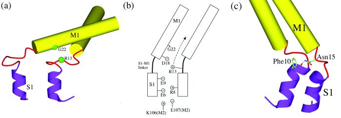
A very interesting amino acid site revealed by mutagenesis study is Gly-22 on the M1 helix (12, 13). This amino acid is buried in a completely hydrophobic environment in the closed state and has been proposed to move into a more hydrophilic environment in the more open intermediate substates (13). The mutagenesis study showed that substitutions of Gly-22 by any hydrophobic residues raised the gating threshold, whereas hydrophilic substitutions decreased the threshold and made the channel favor the subconductance states (with the exception of Gly-22–Glu mutant, which presents a much longer opening duration). These experimental observations could be explained by that a hydrophobic mutation is energetically stabilizing in the hydrophobic environment and makes the M1 helical bundle more resistant to opening. In contrast, the hydrophilic substitutions are energetically destabilizing in the closed state and favor the more hydrophilic environment in the intermediate substates. The present simulation provides support for such an explanation. Gly-22 does move into a more solvent exposed position as soon as the M1 hydrophobic constriction moves apart in stage two. Moreover, in the simulation, during the third stage in which the S1 gate is already very open, there is a persistent spatial proximity between Gly-22 and Arg-13 on the neighboring subunit (counterclockwise one looking from the periplasmic side) (Fig. 6a). A mutation of Gly-22–Glu would induce a strong ionic interaction with Arg-13, and would thus stabilize the substate near the highly open state and lead to a long opening duration. Probably as a consequence of the persistent opening of this mutant channel, Gly-22–Glu is extremely lethal to the bacterial growth (13). These suggestions can be experimentally verified by double mutations such as Gly-22–Glu/Arg-13–Ala. In the final open state, Gly-22 and Arg-13 are separated because of the way that the S1 helices are currently modeled.
Figure 6.
Side-chain interactions. (a) Spatial proximity between Gly-22 and Arg-13 during the third stage of the transition. (b) Schematic illustration of the electrostatic interactions near the S1–M1 linker region. The arrow indicates the direction of traveling of Arg-13 in the process of the gate opening. (c) Interaction involved in Asn-15.
Lys-31 on the M1 helix forms a salt bridge with Asp-84 on the M2 helix of the neighboring subunit. This salt bridge does not break during the entire gating process, and therefore plays a role in maintaining the structural integrity between the M1 and M2 helices during the large gating motions. An ionic cluster is observed mainly in the space between the S1–M1 linker and outer M2 helix (Fig. 6b) and form an intersubunit salt-bridge network. Some of these side chains were mentioned in the modeling study (19). All of the amino acid residues in this cluster are highly conserved in terms of their electrostatic properties. In the closed state, Arg-8 on the S1 helix and Arg-13 on the S1–M1 linker interact with Glu-6 and Glu-9 on the S1 of the neighboring subunit (Fig. 6b). In the intermediate states, Arg-13 meets Asp-18 on the M1 helix in the subunit carrying Glu-6 and Glu-9 before it contacts Gly-22 on the same M1 helix. In addition, Lys-106 and Glu-107 on the M2 helix, from another neighboring subunit, interact with Glu-6, Glu-9, and Arg-8 as well. All of these ionic interactions may contribute to the stability of the S1 bundle and to the formation of subconductance states. There are also many electrostatic interactions distributed around the periplasmic S2 loops and the cytoplasmic S3 helical bundle. Because of the high variability of the sequence in those regions and potential errors in the modeling (19), discussion of these interactions is omitted.
Another interesting hydrophilic interaction observed is from Asn-15, one of the strictly conserved residues on the S1–M1 linker. The amide group of the side chain of Asn-15, in the close state, forms a hydrogen bond with the main chain carbonyl group of Phe-10 on the S1 helix of the neighboring subunit (Fig. 6c). This hydrogen bond may help to stabilize the S1 helical bundle and breaks only when the S1 bundle undergoes a major opening.
Implications in the Gating Mechanisms.
A very important mechanistic conclusion from the present TMD simulation of EcoMscL is that there is no strong energetic coupling between the inner S1 helical bundle and the outer M2 transmembrane helices. Under a milder tension load, the channel can undergo elastic deformation mediated by the tilting motion of the transmembrane helices without disrupting the integrity of the S1 bundle (19). The opening of the S1 bundle under a higher tension load is purely caused by the pulling of the N termini of M1 helices, via the S1–M1 linker, as they undergo final outward horizontal expansion. The lack of strong coupling between the S1 and M2 bundles also makes the S1 helices highly mobile once the strong interactions formed by the three layers of hydrophobic residues (Ile 3, Phe-7, and Phe-10) are loosened up.
These TMD simulation results are generally in line with the hypothesis of two gates: the first weaker one in the M1 helical bundle and the second stronger one in the S1 helical bundle (18, 19). These gates are here shown to be intimately coupled. The opening of the first gate is a prerequisite for the opening of the second gate. This coupling is consistent with the mutagenesis data of Gly-14 on the S1–M1 linker, which showed that a deletion caused the gate to open because it over-tightens the coupling and an insertion desensitized the coupling. However, in a more precise sense, these two gates are just two parts of a single gate. The hydrophobic residues Val-23, Leu-19, Phe-10, Phe-7, and Ile-3 that form the gate are arranged in a continuous fashion (Fig. 2). The sequential rupturing of these tandem hydrophobic layers observed in this simulation, similar to unzipping a continuous hydrophobic zipper, confirms that the two parts of the gate do not behave like two independent gates, rather they are two tandem parts!
Acknowledgments
J.M. acknowledges support from the Robert A. Welch Foundation, the American Cancer Society, the American Heart Association, and the National Science Foundation.
Footnotes
This paper was submitted directly (Track II) to the PNAS office.
References
- 1.Sackin H. Annu Rev Physiol. 1995;57:333–353. doi: 10.1146/annurev.ph.57.030195.002001. [DOI] [PubMed] [Google Scholar]
- 2.Blount P, Moe P C. Trends Microbiol. 1999;7:420–424. doi: 10.1016/s0966-842x(99)01594-2. [DOI] [PubMed] [Google Scholar]
- 3.Blount P, Sukharev S I, Moe P C, Martinac B, Kung C. Methods Enzymol. 1999;294:458–482. doi: 10.1016/s0076-6879(99)94027-2. [DOI] [PubMed] [Google Scholar]
- 4.Batiza A F, Rayment I, Kung C. Structure (London) 1999;7:R99–R103. doi: 10.1016/s0969-2126(99)80061-6. [DOI] [PubMed] [Google Scholar]
- 5.Spencer R H, Chang G, Rees D C. Curr Opin Struct Biol. 1999;9:448–454. doi: 10.1016/S0959-440X(99)80063-3. [DOI] [PubMed] [Google Scholar]
- 6.Sukharev S I, Sigurdson W J, Kung C, Sachs F. J Gen Physiol. 1999;113:525–539. doi: 10.1085/jgp.113.4.525. [DOI] [PMC free article] [PubMed] [Google Scholar]
- 7.Blount P, Sukharev S I, Schroeder M J, Nagle S K, Kung C. Proc Natl Acad Sci USA. 1996;93:11652–11657. doi: 10.1073/pnas.93.21.11652. [DOI] [PMC free article] [PubMed] [Google Scholar]
- 8.Blount P, Sukharev S I, Moe P C, Nagle S K, Kung C. Biol Cell. 1996;87:1–8. [PubMed] [Google Scholar]
- 9.Blount P, Schroeder M J, Kung C. J Biol Chem. 1997;272:32150–32157. doi: 10.1074/jbc.272.51.32150. [DOI] [PubMed] [Google Scholar]
- 10.Hase C C, Le Dain A C, Martinac B. J Membr Biol. 1997;157:17–25. doi: 10.1007/s002329900212. [DOI] [PubMed] [Google Scholar]
- 11.Oakley A J, Martinac B, Wilce M C. Protein Sci. 1999;8:1915–1921. doi: 10.1110/ps.8.10.1915. [DOI] [PMC free article] [PubMed] [Google Scholar]
- 12.Ou X, Blount P, Hoffman R J, Kung C. Proc Natl Acad Sci USA. 1998;95:11471–11475. doi: 10.1073/pnas.95.19.11471. [DOI] [PMC free article] [PubMed] [Google Scholar]
- 13.Yoshimura K, Batiza A, Schroeder M, Blount P, Kung C. Biophys J. 1999;77:1960–1972. doi: 10.1016/S0006-3495(99)77037-2. [DOI] [PMC free article] [PubMed] [Google Scholar]
- 14.Yoshimura K, Batiza A, Kung C. Biophys J. 2001;80:2198–2206. doi: 10.1016/S0006-3495(01)76192-9. [DOI] [PMC free article] [PubMed] [Google Scholar]
- 15.Chang G, Spencer R H, Lee A T, Barclay M T, Rees D C. Science. 1998;282:2220–2226. doi: 10.1126/science.282.5397.2220. [DOI] [PubMed] [Google Scholar]
- 16.Gullingsrud J, Kosztin D, Schulten K. Biophys J. 2001;80:2074–2081. doi: 10.1016/S0006-3495(01)76181-4. [DOI] [PMC free article] [PubMed] [Google Scholar]
- 17.Elmore D E, Dougherty D A. Biophys J. 2001;81:1345–1359. doi: 10.1016/S0006-3495(01)75791-8. [DOI] [PMC free article] [PubMed] [Google Scholar]
- 18.Sukharev S, Betanzos M, Chiang C S, Guy H R. Nature (London) 2001;409:720–724. doi: 10.1038/35055559. [DOI] [PubMed] [Google Scholar]
- 19.Sukharev S, Durell S R, Guy H R. Biophys J. 2001;81:917–936. doi: 10.1016/S0006-3495(01)75751-7. [DOI] [PMC free article] [PubMed] [Google Scholar]
- 20.Schlitter J, Engels M, Kruger P, Jacoby E, Wollmer A. Mol Sim. 1993;10:291–308. [Google Scholar]
- 21.Ma J, Karplus M. Proc Natl Acad Sci USA. 1997;94:11905–11910. doi: 10.1073/pnas.94.22.11905. [DOI] [PMC free article] [PubMed] [Google Scholar]
- 22.Ma J, Sigler P B, Xu Z, Karplus M. J Mol Biol. 2000;302:303–313. doi: 10.1006/jmbi.2000.4014. [DOI] [PubMed] [Google Scholar]
- 23.Brooks B R, Bruccoleri R E, Olafson B D, States D J, Swaminathan S, Karplus M. J Comput Chem. 1983;4:187–217. [Google Scholar]
- 24.Neria E, Fischer S, Karplus M. J Chem Phys. 1996;105:1902–1921. [Google Scholar]
- 25.Jorgensen W L. J Am Chem Soc. 1981;103:335–340. [Google Scholar]
- 26.Allen M P, Tildesley D J. Computer Simulation of Liquids. Oxford: Clarendon; 1980. [Google Scholar]
- 27.Shen Y, Kong Y, Ma J. Proc Natl Acad Sci USA. 2002;99:1949–1953. doi: 10.1073/pnas.042650399. [DOI] [PMC free article] [PubMed] [Google Scholar]
- 28.Kraulis P J. J Appl Crystallogr. 1991;24:946–950. [Google Scholar]
- 29.Bacon D J, Anderson W F. J Mol Graph. 1988;6:219–220. [Google Scholar]


