

Abstract
Purpose
Using finite element analysis, to compare the stress and deformation of six different internal fixation methods for distal femoral fractures to obtain the optimal internal fixation method.
Methods
Create six groups based on different placement methods and fixation methods: 5-hole lateral plate (SP); 5-hole lateral plate + two medial screws (SP + D); 5-hole lateral plate + one trans-plate screw (SP + O); 5-hole lateral plate + one cross screw (SP + C); 5-hole lateral plate + elastic nail (SP + S); 5-hole lateral plate + medial T-shaped plate (SP + T). Observe the displacement distribution and maximum displacement at the fracture site, and stress distribution on the medial fracture fragment and internal fixation.
Results
After applying the load, mechanical indicators for internal fixation and bone blocks were obtained for all six models by finite element method. The model with a lateral single plate showed max internal fixation stress of 221.75 MPa, which was greater than other models. On the other hand, the model with a 5-hole lateral plate and medial T-shaped plate showed the smallest internal fixation stress (125.74 MPa) and the smallest total femoral deformation (0.99416 mm).
Conclusion
The combination of a 5-hole lateral plate and a medial T-shaped plate demonstrated significant biomechanical advantage compared to the other five groups. Although the 5-hole lateral plate model is slightly inferior compared to the 5-hole lateral plate and medial T-shaped plate, it remains an effective and safe fixation solution for AO/OTA 33C1 type fractures.
Keywords: Distal femur fracture, Finite element analysis, Locking Plate
Introduction
Distal femur fractures are severe intra-articular fractures of the lower extremities, with an incidence rate of about 1.1%. They account for approximately 4–6% of femoral fractures. Distal femur fractures show a bimodal age distribution [1], High-speed traffic accidents are a significant cause of distal femur fractures, which is particularly common among young and middle-aged individuals. On the other hand, low-energy mechanisms are likely the main cause of distal femur fractures in the elderly [2]. Statistically, there are numerous reports of distal femur fractures annually, imposing significant economic burdens on patients and society. According to the AO/OTA classification, type 33C1 fractures are unstable with multiple fracture fragments, characterized by high shear forces and stresses, which may lead to failure of internal fixation at the distal femur. This can result in delayed or non-union of the fracture, as well as complications such as plate breakage, displacement of fracture fragments, or infection [3]. According to Gele B. Moloney’ s research, the non-union rate for distal femur fractures can reach up to 20% [4], The probability of infection is also quite high.
Indeed, the placement of lateral locking plates and screws remains a common choice for treating distal femur fractures [5]. Traditional anterolateral incision locking plates offer a biomechanically viable fixation method, ensuring the stability of the fracture fragments and promoting fracture healing. Their principle of operation primarily involves providing multi-point fixation through locking screws at both the distal and proximal ends of the fracture, achieving resistance to torsion and bending. However, numerous studies suggest that relying solely on lateral plates may have limitations [6], especially in cases where the fracture fragments are displaced or unstable [7]. To address this issue, additional screws can usually be inserted at the distal femur or an additional medial plate can be added to reduce the instability of the fracture fragments. When a lateral plate is placed alone, the anti-bending capacity of the internal fixation may not be strong enough. Research by Kanai Garala suggests that adding other femoral implants might reduce the phenomenon of stress shielding, thereby promoting healing [8]. However, these studies have not provided a more intuitive representation of the results. Torieh reported on 16 patients with distal femoral comminuted fractures, all of whom underwent dual plating fixation and ultimately achieved good recovery [9]. At the same time, adding screws or additional internal plating can result in less femoral deformation and alleviate the shear forces borne by the screws.
Intramedullary nail is one of the methods for treating femoral fractures. According to recent research, the biomechanical stability of intramedullary nail implantation is better than that of using lateral femoral reconstruction plate for intertrochanteric fractures. Also, the von Mises stress on the intramedullary nail is lower than that of the reconstruction plate [10]. In another biomechanical study, the differences between four types of intramedullary nails were studied, which also showed that intramedullary nails can achieve good benefits in the treatment of femoral fractures [11]. These studies provide a certain clinical basis for the application of lateral steel plates and medial elastic nails, but it is still unknown whether lateral steel plates and medial elastic nails can bring biomechanical stability, and how stress, strain, and other indicators of fracture fragments and internal fixation change.
This study aims to explore which of the six internal fixation methods can minimize the maximum stress of fracture fragments and internal fixation, effectively reducing the maximum micro motion between fracture fragments, using finite element analysis. Can the innovative solution of elastic nails and outer steel plates achieve biomechanical stability.
Materials and methods
Selecting one healthy male volunteer aged 24, who provided informed consent for the experimental protocol, and whose X-ray images excluded hip deformities, tumors, fractures, and surgical history. The experimental equipment and software tools included: a 256-slice spiral CT scanner.
From Siemens, Germany, the 3D modeling software Mimics 21.0 from Materialise, reverse engineering software Geomagic Studio 2017 from Geomagic, mechanical design software SolidWorks 2021 from Dassault Systèmes and finite element calculation software Ansys 24 from Ansys Inc. In this study the research subject underwent femoral spiral CT scans, resulting in initial tomographic image data in Dicom format. These images were then imported into Mimics software, where grayscale values were used to identify and extract an initial femoral model. This model was exported as an Stl file. Next, the Stl data was imported into Geomagic Studio software for surface optimization and surface fitting. The software was also used to differentiate between cortical bone and cancellous bone. Subsequently, the model was imported into SolidWorks software for surface error checking and further model editing. This multi-step process ensures a high-quality 3D model of the femur, which can be used for detailed analysis and mechanical simulations.
Constructing the geometric model
The research subject underwent a spiral CT scan of the femur, resulting in initial tomographic image data in Dicom format. These images were imported into the Mimics software, where grayscale values were used to identify and initially extract the femoral model, which was then exported as an Stl model data file. The data was subsequently imported into Geomagic Studio for external optimization and surface fitting, with the overall offset distinguishing cortical bone from cancellous bone. The model was further processed in SolidWorks for surface error checking, interference detection, and model editing. Through Boolean operations, the cortical and cancellous components of the femur were assembled together, ultimately constructing a comprehensive model of the entire length of the femur.
Establishment of AO/OTA 33C1 fracture model
The femur model, after undergoing Boolean assembly operations, was imported into SolidWorks 2021 (developed by Dassault Systèmes in France). Based on the characteristics of AO/OTA 33C1 distal femoral fractures, where the fracture lines are all within 15 cm of the distal end of the femur, a reference plane passing through the distal end of the femur was established. This reference plane was used to create a sketch that divided the distal part of the femur, simulating an AO/OTA 33C1 distal femoral fracture. The fracture model is shown in Fig. 1.
Fig. 1.
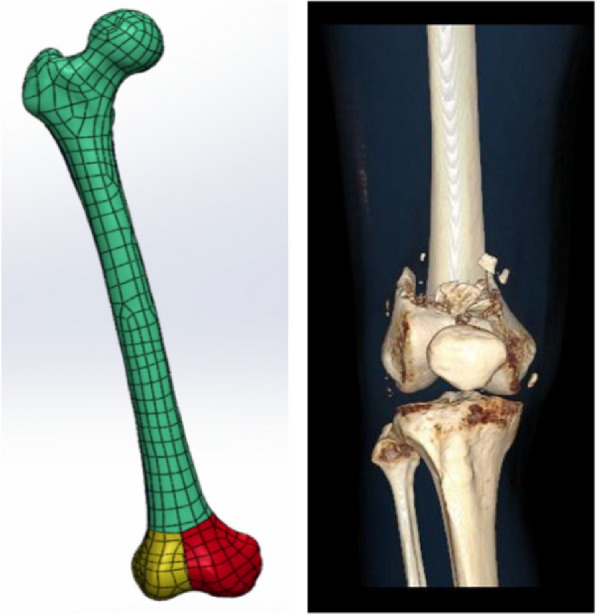
T-shaped fracture model and 3D CT images of T-shaped fracture
Constructing the internal fixation model
Based on clinical experience of the usage of plates and screws, six internal fixation models for distal femoral fractures were created using SolidWorks. For the sake of computational simplicity, the rounded edges of the plates and the chamfered effects of the plate holes were simplified, which does not affect the experimental results. In this study, we innovatively combined lateral plates with elastic nails, which were used to treat T-shaped distal femoral fractures. The six models are shown in Figs. 2 and 3.
Fig. 2.

Six internal fixation models: a Lateral Single Plate group (SP). b Lateral Plate + Elastic Nail group (SP + S). c Lateral Plate + Cross Screw group (SP + C). d Lateral Plate + Double Screw group (SP + D). e Lateral Plate + Oblique Screw group (SP + O). f Lateral Plate + Medial T-shaped Plate group (SP + T)
Fig. 3.
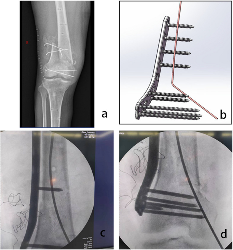
A case of distal femoral fracture treated with a combination of lateral plate and elastic nail internal fixation
Six internal fixation models
The implants in the internal fixation system are based on the standard model, and the outer steel plates in all groups are placed in the same position. The diameter of the screw on the lateral plate is 4 mm, which is a locking screw. The diameter of the inner screw in group SP + C and SP + D is also 4 mm, which is a regular tension screw. In the lateral plate model, the lateral plate has a length of 172 mm, a width of 16 mm, with a hole diameter of 5.6 mm, and a thickness of 4 mm. The screw lengths vary from 17 to 65 mm, with the threaded length being equal to the screw length. All screws of the lateral plate model are placed perpendicular to the steel plate in the model, with intra-articular screws not leaving the contralateral cortex and extra articular screws leaving the contralateral cortex. For the lateral plate + double screws model group, two ordinary compression screws are inserted into the medial condyle of the femur parallel to the lateral joint surface, both with a length of 65 mm.In the lateral plate + oblique screw group, an additional ordinary compression screw is inserted through the 5th hole on the plate at an approximately 60-degree angle into the distal part of the femur, with a screw length of 65 mm. In the lateral plate + cross screw group, an additional screw is also inserted into the femur at a 60-degree angle to the plate. In the lateral plate + elastic nail group, the elastic nail is placed appropriately within the medullary cavity of the femur. In the lateral plate + medial T-shaped plate model group, the total length of the T-shaped plate is 70 mm, with 5 mm apertures and a thickness of 3 mm. The locking screw lengths on the T-plate ranges from 15 to 19 mm, with a screw diameter of 3 mm. According to the AO principle, the length of the internal fixation steel plate for distal femoral fractures should have 6–8 cortical layers (i.e. 3–4 screws) on both sides of the full bone fracture line, so the above steel plate length selection is made.
Material setup
Based on previous research, computational models have all been considered to be made of ideal continuous, homogeneous, isotropic linear elastic materials [12]. In this study, the material parameters for the finite element models were assumed as follows: the elastic modulus of cortical bone was 16800 MPa, and the elastic modulus of cancellous bone was 840 MPa, with Poisson’s ratios of 0.3 and 0.2, respectively. The elastic modulus of the titanium alloy (Ti-6Al-7Nb) used was 110000 MPa, with a Poisson’s ratio of 0.35.A convergence test was conducted using tetrahedral elements with sizes ranging from 1.0 mm to 1.5 mm. The results showed that the calculated equivalent stress values were similar for those meshes. Based on this, the meshes for the femur and internal fixators in this study were set at 1.5 mm to generate the elements. The elements and node counts for the six finite element models are listed in (Table 1).
Table 1.
Number of meshes and nodes
| SP | SP + S | SP + C | SP + D | SP + O | SP + T | |
|---|---|---|---|---|---|---|
| Number of nodes | 2664374 | 2818195 | 2842054 | 2762639 | 3185379 | 2442632 |
| Number of elements | 1579942 | 1669421 | 1686017 | 1637292 | 1888147 | 1449654 |
Constraints and mechanical loading
Based on Saeideh Hamidi’s finite element analysis, a simulation of single-leg standing was conducted, applying a load of 730 N vertically to the femoral head. The friction coefficient between each pair of fracture fragments and between the lateral plate and the bone is 0.3 [13]. The lateral plate and the screws on the lateral plate are set in fixed contact with the bone. The elastic nails and bones in group SP + S have fixed contact with the inner screws of group SP + C and group SP + D, while the screws on the T-plate and bone fragments in group SP + T have fixed contact with each other. The friction coefficient between the T-plate and bone fragments is 0.3.The distal end of the femur was set in a fixed state. The load setting simulates the reaction forces of several major muscles and ilium in the proximal femur. The reaction force of the iliopsoas is applied to the center of the femoral head, perpendicular to the femoral head and forming a 20° downward angle with the long axis of the femur, with a magnitude of 730N. The force of the abductor muscle is applied to the greater trochanter of the femur, forming an inward upward angle of 20° with the long axis of the femur, with a magnitude of 300N. The force of the iliopsoas muscle is applied to the greater trochanter of the femur, forming an inward upward angle of 45° with the long axis of the femur, with a magnitude of 188N. The force of the lateral thigh muscle is applied to the greater trochanter of the femur, parallel to the long axis of the femur and downward, with a magnitude of 192 N [14]. Load Setting is shown in Fig. 4.
Fig. 4.

The distal end of the femur is fixed with relative displacement constraints. A 730 N of iliac reaction force (directed 20° downward relative to the long axis of the femur), directly facing the center of the femoral head. B 300 N of abductor force (directed 20° upward relative to the long axis of the femur). C 188 N of iliopsoas force (directed 45° upward relative to the long axis of the femur). D 192 N of vastus lateralis force (parallel to the long axis of the femur)
Results
Total deformation of the full length of the femur
The total deformation of the entire length of the femur is shown (Fig. 5, Table 2). Generally, as the implants for femoral fixation increase, the total deformation of the entire length of the femur can be effectively reduced. Under the condition of single-leg standing, the total deformation of the entire length of the femur in Group A, with a deformation of 1.7754 mm, is significantly larger than that in Group B and Group F. The total deformation of the entire length of the femur in Group A, with a single plate fixation model, is actually 137% of that in Group B, 117% of that in Group C (single plate + cross screws), 108% of that in Group D (single plate + double screws), 116% of that in Group E (single plate + oblique screws), and 178% of that in GroupF (singleplate + T-plate).
Fig. 5.

Contours of the total deformation of the entire length of the femur
Table 2.
Summary of data for the six internal fixation models
| SP | SP + S | SP + C | SP + D | SP + O | SP + T | |
|---|---|---|---|---|---|---|
| Total deformation along the entire length of the femur.(mm) | 1.7754 | 1.2947 | 1.511 | 1.6406 | 1.5289 | 0.99416 |
| Maximum displacement at the fracture surface.(mm) | 0.18421 | 0.1348 | 0.15716 | 0.16809 | 0.16063 | 0.10617 |
| Maximum stress on the fracture fragment.(MPa) | 678.12 | 708.22 | 518.07 | 915.5 | 539.85 | 264.26 |
| Maximum stress on the internal fixation.(MPa) | 221.75 | 173.45 | 168.2 | 193.22 | 195.49 | 125.74 |
Max displacement at the fracture interface
The maximum displacement of the fracture surface in the single plate fracture model is 0.18421 mm. After adding the elastic nail, the maximum displacement of the fracture surface significantly decreased to 0.1348 mm, which is 73% of the single plate model in Group A. Placing an lateral plate + internal T-plate can reduce the maximum displacement of the fracture surface even more, to 0.10617 mm, which is 57% of Group A. The lateral plate + elastic nail fracture model group is 73% of Group A, the lateral plate + cross screw group is 85% of Group A, the lateral plate + double screw group is 91% of Group A, and the external plate + oblique screw group is 87% of Group A (as shown in Fig. 6).
Fig. 6.

Contours of maximum displacement at the fracture surface
Maximum von mises stress distributions at the fracture block
The maximum von Mises stress on the fracture block occurs on the inner fracture block. The maximum VMS on the fracture block in the lateral plate group is 678.12 MPa. When an elastic nail is added, the maximum stress on the fracture block increases slightly to 708.22Mpa. The maximum stress on the fracture block in the lateral plate + cross screw group is 76% of the lateral single plate group. The maximum stress on the fracture block in the lateral plate + double screw group is 135% of the lateral single plate group. The maximum stress on the fracture block in the lateral plate + oblique screw group is 79% of the lateral single plate group. The maximum stress on the fracture block in the lateral plate + internal T-plate group is 38% of the lateral single plate group (as shown in Fig. 7).
Fig. 7.

Contours of maximum von Mises stress on fracture block
Maximum von mises stress on the internal fixation
The maximum von Mises stress of the internal fixation occurs at the nail hole at the uppermost part of the lateral plate. The maximum von Mises stress of the internal fixation in the lateral single plate group is 221.75Mpa. When an elastic nail is added, the maximum stress of the internal fixation is 78% of the lateral single plate group. The maximum von Mises stress of the internal fixation in the external plate + cross screw group is 75% of the lateral single plate group. The maximum von Mises stress of the internal fixation in the lateral plate + double screw group is 87% of the lateral single plate group. The maximum von Mises stress of the internal fixation in the lateral plate + oblique screw group is 88% of the lateral single plate group. The maximum von Mises stress of the internal fixation in the lateral plate + internal T-plate group is 56% of the lateral single plate group (as shown In Fig. 8).
Fig. 8.

Contours of maximum von Mises stress on internal fixation
Discussion
In recent years [15], as scholars have focused their attention on evaluating the clinical outcomes of distal femoral fracture fixation with plates, it has been observed that the incidence of complications in distal femoral fractures remains high [16]. Additionally, prolonged stress concentration on the plate can lead to fatigue fracture of the plate, resulting in surgical failure [13]. Current finite element studies have found that improper placement of internal fixation may lead to transverse movement between fracture fragments [17].
In distal femoral AO/OTA 33C1 type fractures, the placement of intramedullary elastic nails can reduce the total deformation of the entire length of the femur by 27%, outperforming the results of groups SP + C, SP + D, and SP + O, which show reductions of 15%, 8%, and 13%, respectively. Additionally, it can be observed that there is not much difference in reducing total deformation over the entire length of the femur among groups SP + C, SP + D, and SP + O. Unlike groups SP + C, SP + D, and SP + O, the addition of a medial T-plate at the distal femur while placing a lateral plate can significantly reduce the total deformation over the entire length of the femur, with the result being 0.99416 mm, which is 55% of the result (1.7754 mm) when only an lateral single plate is placed in group SP. Previous studies have shown [18] that irregular axial or transverse deformations can prolong the healing time of fracture surfaces, while a certain amount of regular axial deformation may promote healing at the fracture site.
Previous studies on the distal femur have conducted finite element analysis to examine the effects of different lengths of lateral plates on bone and internal fixation stress and deformation [19]. In this article, we focus on the selection of medial implants. Using a single-plate fracture model, the maximum axial displacement of the fracture surface was 0.18421 mm. The results showed that regardless of the type of internal fixation device implanted in the medial condyle, the maximum displacement of the fracture surface could be reduced. The results indicate that the reduction in maximum axial displacement provided by group SP + T was significantly better than those of the other five finite element fracture models.
For the lateral plate + medial elastic pin fracture model proposed in this article, the maximum axial displacement of the fracture surface showed a relative advantage, second only to the lateral plate + medial T-plate group. There was no significant difference between the lateral plate + medial cross screws group and the lateral plate + oblique screws group. Groups SP + C and SP + O were better than group SP + D, which may indicate that passing nails through more fracture blocks or using longer nails on the medial side could result in smaller fracture block displacements. This aligns with reports by K Stoffel, J Lu and Qi-Fang He, among others [20–22], that under the reinforcement of bilateral lateral and medial plates on the femur, good biomechanical effects are achieved, clinical healing outcomes are satisfactory, and the recovery after fracture is also improved. This is consistent with the results of our finite element research, which show that placing a lateral plate + medial T-plate provides overall superior biomechanical stability compared to other groups. The innovative SP + S group has smaller incisions for patients. In finite element analysis, it can effectively reduce the lateral displacement of the fracture block and the stress on the internal fixation, bringing more benefits to patients. Interestingly, the fracture block with the largest stress is the lateral plate + double screw fracture model group reaching 915.5 MPa. Therefore, overly pursuing the stability of the fracture block may sacrifice stress superiority, which may be related to the two transverse screws not being perpendicular to the fracture site and the failure to reconstruct the medial column. The lateral plate group + medial T-plate still outperforms the other five groups by having the lowest stress levels in the fracture fragment. The maximum stress on the internal fixation of all six fracture models appears at the screw hole closest to the distal end of the lateral plate. The maximum internal fixation stress in the lateral single-plate fracture model group was 221.75 MPa, which is close to that of groups SP + D and SP + O. The SP + S group, which incorporated elastic pins, significantly reduced the maximum stress on the internal fixation. The maximum stress on the internal fixation might be related to the length of the elastic pins, but our study did not quantify the optimal length of the elastic pins. The SP + T group still provided the best reduction in maximum internal fixation stress, reaching 62%.
Our study has several limitations. Whether the results of our finite element research truly align with the clinical reality remains to be further considered. The sample in this study was from a 24-year-old male subject, who only tested the stress of the internal fixation system and the displacement of the fracture surface when standing on one leg. The study did not explore the effects of other exercise scenarios or bone density on the results. The accuracy of this experiment may decrease when facing elderly patients or dynamic situations. Finite element analysis simplifies the bone and internal fixation models using various theories, assuming that the femur is composed of isotropic and elastic materials. In addition, we used a single length outer steel plate for testing, and the screws on the steel plate were locking screws. We simplified the internal fixing steel plate and screws, removing chamfers and rounded corners at the edges, which may also lead to a decrease in accuracy of the results. The fixed contact between the bones and screws in the model is different from the actual situation, which will result in a decrease in displacement between the fracture blocks and an increase in stress on the internal fixation and bones. Therefore, only the stability between the fracture blocks is considered, also the relationship between micro motion and fracture healing needs to be considered. In addition, to reduce complexity, we only included the forces exerted by a few major muscles and iliac bones. Undoubtedly, the prognosis of fracture treatment is influenced by many factors, such as the surgeon’s personal surgical preferences, the patient’s overall condition, and the local condition of the fracture site [23]. It is clear that these differences are not within the scope of our study, and we assumed that surgical reduction achieved anatomic reduction [24]. Moreover, although in all six groups of finite element analysis, the relative position of the lateral plate to the distal end of the femur was fixed, this is not the case in actual clinical practice. In short, we did not conduct a quantitative study on the relative position of the internal fixation to the bone.
Conclusions
Based on the load, internal fixation, and skeletal parameter settings in this study, the SP + T group performed better than the other groups, with a maximum stress of 125.74 MPa for internal fixation and 264.26 MPa for fracture fragments. The stress on the internal fixation within the SP + S group is 173.45Mpa, which is also better than that of the SP group. This may suggest that in clinical practice, adding T-shaped plates to to the lateral steel plate can achieve better mechanical stability, and of course, adding elastic nails is also a good choice. However, the results may differ from reality to some extent, which is also something we need to further verify in the future.
Acknowledgements
Not applicable.
Authors’ contributions
Jianxiong Zhang: Investigation, Data curation, software Jiadi Le: Writing original draft. Zhenghao Wu: Writing review & editing. Long Chen: Manuscript correction.
Funding
No funding.
Data availability
The datasets analyzed during this study are available from the corresponding author on reasonable request.
Declarations
Ethics approval and consent to participate
The study was approved by the Ethics Committee of the Second Affiliated Hospital and Yuying Children's Hospital of Wenzhou Medical University (approval No. 2024–K–200–01). Informed consent has been obtained from the participant. Our research adheres to the principles of the Helsinki Declaration.
Consent for publication
Not applicable.
Competing interests
The authors declare no competing interests.
Footnotes
Publisher’s Note
Springer Nature remains neutral with regard to jurisdictional claims in published maps and institutional affiliations.
References
- 1.Paulsson M, Ekholm C, Tranberg R, Rolfson O, Geijer M. Using a traction table for fracture reduction during Minimally Invasive Plate Osteosynthesis (MIPO) of distal femoral fractures provides anatomical alignment. J Clin Med. 2023;12(12):1–17. [DOI] [PMC free article] [PubMed]
- 2.Kubiak EN, Fulkerson E, Strauss E, Egol KA. The evolution of locked plates. J Bone Joint Surg Am. 2006;88(Suppl 4):189–200. [DOI] [PubMed] [Google Scholar]
- 3.Ebraheim NA, Kelley LH, Liu X, Thomas IS, Steiner RB, Liu J. Periprosthetic distal femur fracture after total knee arthroplasty: a systematic review. Orthop Surg. 2015;7(4):297–305. [DOI] [PMC free article] [PubMed] [Google Scholar]
- 4.Moloney GB, Pan T, Van Eck CF, Patel D, Tarkin I. Geriatric distal femur fracture: are we underestimating the rate of local and systemic complications? Injury. 2016;47(8):1732–6. [DOI] [PubMed] [Google Scholar]
- 5.Leung F, Fang CX, Yung CSY, Leung FKL. Determination of the ideal plate for medial femoral condyle fracture fixation: an anatomical fit and biomechanical study. BMC Musculoskelet Disord. 2024;25(1):296. [DOI] [PMC free article] [PubMed] [Google Scholar]
- 6.Southeast Fracture Consortium. LCP Versus LISS in the treatment of open and closed distal femur fractures: does it make a difference? J Orthop Trauma. 2016;30(6):e212–216. [DOI] [PubMed]
- 7.Kriechling P, Bowley ALW, Ross LA, Moran M, Scott CEH. Double plating is a suitable option for periprosthetic distal femur fracture compared to single plate fixation and distal femoral arthroplasty. Bone Jt Open. 2024;5(6):489–98. [DOI] [PMC free article] [PubMed] [Google Scholar]
- 8.Garala K, Ramoutar D, Li J, et al. Distal femoral fractures: a comparison between single lateral plate fixation and a combined femoral nail and plate fixation. Injury. 2022;53(2):634–9. [DOI] [PubMed] [Google Scholar]
- 9.Imam MA, Torieh A, Matthana A. Double plating of intra-articular multifragmentary C3-type distal femoral fractures through the anterior approach. Eur J Orthop Surg Traumatol. 2018;28(1):121–30. [DOI] [PubMed] [Google Scholar]
- 10.Zhang J, Wei Y, Li G, Jian W, Yu B. Biomechanical comparison of an intramedullary nail combined with a reconstruction plate combination versus a single intramedullary nail in unstable intertrochanteric fractures with lateral femoral wall fracture: a finite element analysis. Acta Orthop Traumatol Turc. 2024;58(2):89–94. [DOI] [PMC free article] [PubMed] [Google Scholar]
- 11.Tang Z, Zhu Z, Lv Y, et al. Biomechanical difference analysis of new and classic intramedullary nail devices in the treatment of basal femoral neck fractures: finite element analysis. BMC Musculoskelet Disord. 2024;25(1):697. [DOI] [PMC free article] [PubMed] [Google Scholar]
- 12.Baca V, Horak Z, Mikulenka P, Dzupa V. Comparison of an inhomogeneous orthotropic and isotropic material models used for FE analyses. Med Eng Phys. 2008;30(7):924–30. [DOI] [PubMed] [Google Scholar]
- 13.Zhang W, Li J, Zhang H, et al. Biomechanical assessment of single LISS versus double-plate osteosynthesis in the AO type 33–C2 fractures: a finite element analysis. Injury. 2018;49(12):2142–6. [DOI] [PubMed] [Google Scholar]
- 14.Hamidi S, Khosravifard A, Hematiyan MR, Dehghani J. A comparative mechanical study of two types of femur bone implant using the finite element method. Int J Numer Method Biomed Eng. 2021;37(6): e3459. [DOI] [PubMed] [Google Scholar]
- 15.Epari DR, Duda GN, Thompson MS. Mechanobiology of bone healing and regeneration: in vivo models. Proc Inst Mech Eng H. 2010;224(12):1543–53. [DOI] [PubMed] [Google Scholar]
- 16.Meneghini RM, Keyes BJ, Reddy KK, Maar DC. Modern retrograde intramedullary nails versus periarticular locked plates for supracondylar femur fractures after total knee arthroplasty. J Arthroplasty. 2014;29(7):1478–81. [DOI] [PubMed] [Google Scholar]
- 17.Jung CH, Cha Y, Yoon HS, et al. Mechanical effects of surgical variations in the femoral neck system on Pauwels type III femoral neck fracture: a finite element analysis. Bone Joint Res. 2022;11(2):102–11. [DOI] [PMC free article] [PubMed] [Google Scholar]
- 18.Elkins J, Marsh JL, Lujan T, et al. Motion predicts clinical callus formation: construct-specific finite element analysis of supracondylar femoral fractures. J Bone Joint Surg Am. 2016;98(4):276–84. [DOI] [PMC free article] [PubMed] [Google Scholar]
- 19.He Y, Liu Y, Yin B, et al. Application of finite element analysis combined with virtual computer in preoperative planning of distal femoral fracture. Front Surg. 2022;9:803541. [DOI] [PMC free article] [PubMed] [Google Scholar]
- 20.Stoffel K, Sommer C, Lee M, Zhu TY, Schwieger K, Finkemeier C. Double fixation for complex distal femoral fractures. EFORT Open Rev. 2022;7(4):274–86. [DOI] [PMC free article] [PubMed] [Google Scholar]
- 21.Lu J, Guo SC, Wang QY, Sheng JG, Tao SC. J-bone graft with double locking plate: a symphony of mechanics and biology for atrophic distal femoral non-union with bone defect. J Orthop Surg Res. 2020;15(1):144. [DOI] [PMC free article] [PubMed] [Google Scholar]
- 22.He QF, Wang HX, Sun H, et al. Medial open-wedge osteotomy with double-plate fixation for varus malunion of the distal femur. Orthop Surg. 2019;11(1):82–90. [DOI] [PMC free article] [PubMed] [Google Scholar]
- 23.Rodriguez EK, Boulton C, Weaver MJ, et al. Predictive factors of distal femoral fracture nonunion after lateral locked plating: a retrospective multicenter case-control study of 283 fractures. Injury. 2014;45(3):554–9. [DOI] [PubMed] [Google Scholar]
- 24.Babst R, Beeres FJP, Link BC. Definitions and explanations on the topic of fracture reduction. Unfallchirurg. 2019;122(2):88–94. [DOI] [PubMed] [Google Scholar]
Associated Data
This section collects any data citations, data availability statements, or supplementary materials included in this article.
Data Availability Statement
The datasets analyzed during this study are available from the corresponding author on reasonable request.