

Abstract
This study proposes a comprehensive seismic retrofit strategy for a 24-story steel building originally designed according to the outdated seismic code (GB 50011-2001). The building suffers from structural deficiencies, including excessive torsional displacement, insufficient axial load-bearing capacity of columns, and the presence of weak-story mechanisms. In this retrofit, BRB were adopted to make the structure comply with the modern seismic code (GB 50011-2010). Through systematic analysis using the YJK structural software, BRB were arranged at the mid-spans in the Y-direction of the structure. The results verified that the BRB system enhances the lateral stiffness of the structure while maintaining its architectural functionality. Compared with the base isolation alternative, it reduces the construction cost. Moreover, the structure can meet the requirements of GB 50011-2010 without disrupting its normal operation. This work establishes a reference framework for cost-effective seismic retrofitting of high-rise buildings.
Keywords: Strengthening and renovation, Buckling-restrained brace (BRB), Energy dissipation substructure, Pushover analysis
Subject terms: Civil engineering, Structural materials
Introduction
Buildings serve not only as spaces for habitation and work but also must consider aesthetic design alongside functional requirements, resulting in a variety of forms. With the rapid advancement of modern construction technologies, numerous public and landmark buildings have been developed. However, the frequent occurrence of seismic events poses a significant threat to the safety of these structures, leading to substantial losses in both life and property. Consequently, the design for seismic performance in building structures is critically important. Currently, the growth rate of newly constructed buildings in China is gradually decelerating. For existing building structures that are already operational, seismic strengthening and renovation have become essential measures to enhance earthquake resistance, ensure occupant safety, and prolong the service life of these buildings an endeavor with considerable practical significance.
In recent years, many scholars have conducted research on energy dissipation and vibration reduction technologies. For example, in the references, Xu et al.1–4 research on rubber bearings composed of different materials and applied them to practical engineering; In references5–7, the intensive study was conducted on the reinforcement and seismic control technology of RC frame structures using viscoelastic dampers. Xu et al.8 proposed a dynamic response analysis method that takes into account the nonlinearity of the multi-dimensional seismic isolation and damping device (MEIMD). Xu et al.9 proposed a new multi-dimensional seismic isolation and damping device, and the results show that this device has good energy dissipation capacity in the vertical direction. Yang et al.10 studied the application of the MR damping system in structural vibration control and provided an effective integrated optimization method to mitigate the torsional vibration in spatially irregular structures. Liu et al.11 proposed an efficient 3D-BIS seismic response analysis method. Tao et al.12 proposed an energy-based framework for the rapid assessment of the damage and vulnerability of regional buildings under the mainshock-aftershock sequence. Xu et al.13 proposed a mathematical model of the microstructure of a viscoelastic damper. The proposed mathematical model of the microstructure can perfectly depict the dynamic characteristics of the viscoelastic damper under different test conditions. Hu et al.14 proposed a new viscoelastic isolation and damping device (VEIMD) for PSWPS based on high-damping viscoelastic materials, and developed an effective method to improve the seismic performance of rigid lightweight structures similar to PSWPS. Buckling-restrained braces have emerged as an advanced seismic technology that has garnered increasing attention and achieved remarkable progress in both research and application. Buckling-restrained brace (BRB) was first proposed by Japanese scholar Yoshino15. Nakamura16 found that buckling restrained supports made of ordinary steel and low yield point steel exhibited good large strain fatigue performance. Federico et al.17,18 studied the seismic performance of BRB concrete frames through finite element analysis and experimental comparison. In Black et al.19 conducted research and discovered that the use of unbonded braces in buckling-restrained braces can enhance the seismic performance and energy dissipation capacity of new structures and existing structures. In Fahnestock et al.20 found through research that a suitable buckling-restrained brace frame can withstand a large amount of seismic input energy and maintain its load-bearing capacity. In Chou et al.21 studied the seismic performance of buckling-restrained braces installed in frames. In Guneyisi et al.22 studied the application of buckling-restrained braces in the seismic retrofit of steel moment-resisting frame buildings, and found that it significantly improved the seismic response of the original buildings. In Guneyisi et al.23 considered two sets of seismic responses representing the design. By comparing the original building structure with the structure using buckling-restrained braces, they found that buckling-restrained braces were very effective in reducing seismic responses. In Wang Chunlin24 developed high-performance buckling restrained supports. After the Beiling earthquake, the United States began to study buckling restrained supports25, and in the 1960s, 344 buckling restrained supports were used to reinforce the Bennett building26. Later, domestic scholar Wang Chunlin27 pointed out that during the loading process, the core part of the BRB will undergo multi wave micro amplitude buckling under the action of external restrained elements, causing uneven strain distribution in the core plate, and the strain concentration will become the weak point of core plate failure. In response to this issue, Matsui and Takeuchi28 proposed the concept of strain concentration number for BRB core plates. In Almeida et al.29 conducted an evaluation through nonlinear static and dynamic numerical analyses to study the applicability and effectiveness of buckling-restrained braces in the retrofit of existing building structures. In Barbagallo et al.30 proposed a design method for seismic strengthening interventions using buckling-restrained braces. In Du et al.31 studied the performance of BRBs under seismic response in reinforced concrete frame structures and quantified the shear ratio of the BRB-resistant layer. In Castaldo et al.32 studied the effectiveness of buckling-restrained braces in the seismic retrofit of reinforced concrete buildings with masonry infills. Chao Hsien Li33 from the University of California conducted buckling constrained support constant amplitude loading tests in 2022. In Rafi et al.34 studied the performance of reinforced concrete frames strengthened with buckling-restrained braces under seismic response. In Bouderradji et al.35 studied the influence of the distribution and location of two types of BRB supports on the seismic performance of a five-story building.
This paper will take the renovation project of a certain high-rise building as the case study object, explore the technologies related to seismic strengthening and renovation. Buckling-restrained braces will be used in the engineering strengthening, and an analysis will be carried out on them to examine the role they play in the seismic-resistance process.
Project overview
The height of this project is 89.55 m, comprising 24 floors above ground and one underground level. The original structural design was completed in 2006, with the construction finalized in 2010, utilizing a frame-shear wall structural system. In response to increased functional requirements, the building underwent renovations in 2020. The specific adjustments made are as follows: Functional reconfiguration of floors 1 to 24; Addition of three additional floors on the roof, raising the total height to 98.55 m; Upgrading and renovation of interior decorations; Facade refurbishment. Following an assessment by a qualified appraisal unit, it was determined that the original structure possesses a safety rating of C. Consequently, it is imperative to evaluate the structural safety implications arising from these changes in building functions and to implement renovation and strengthening designs for any areas that do not comply with current regulations.
Renovation design
Firstly, review the existing structural model of the project, as shown in Fig. 1.
Fig. 1.
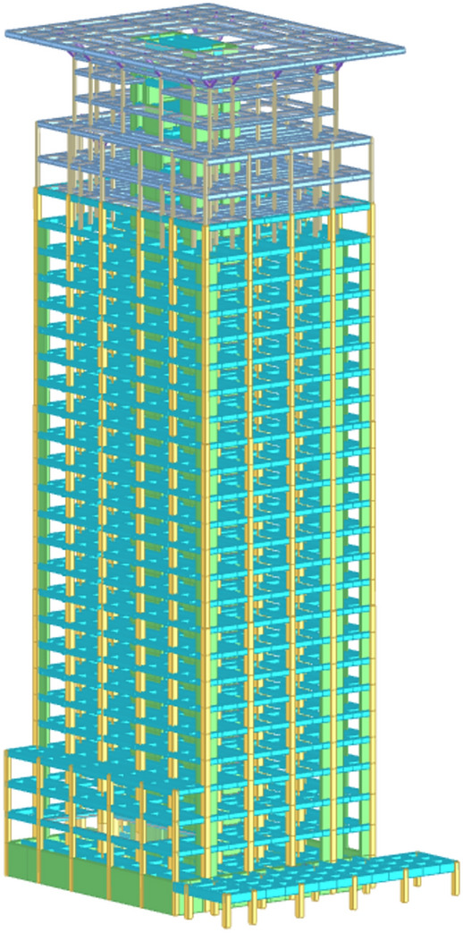
Existing structural model. Create software: YJK4.1.1, https://www.yjk.cn/.
The initial design of this project was finalized in 2006, with the completion drawings being completed in 2010. At that time, construction adhered to the 01 series standards and complied with the 2001 version of the Chinese Seismic Code GB 50011-2001. Subsequently, while the service life of the reinforced structure will not be extended, it must conform to the Chinese seismic code established in 2010. The structural design parameters are as follows:
Seismic precautionary intensity is 8, earthquake group is 2, site soil category is II, characteristic period is 0.40; The seismic resistance level is Level 1. The partial coefficient of dead load is taken as 1.2, and the partial coefficient of live load is taken as 1.4. The overall indicators are computed based on the rigid-diaphragm assumption. The structural model is developed using the YJK software.
China’s seismic zoning system categorizes regions into seismic intensity levels from 6 to 9 (equivalent to peak ground acceleration, PGA, ranging from 0.05 to 0.4 g). The seismic fortification intensity of this structure is set at Intensity Level 8. Intensity Level 8 (PGA = 0.07 g) indicates the seismic fortification requirements of this area, and 0.07 g is the corresponding design-basic PGA value.
According to China’s Code for Seismic Design of Buildings (GB 50011), the seismic-design categories of concrete frames are classified into four grades, namely Grade 1 to Grade 4. Grade 1 has the most stringent seismic-design requirements, while Grade 4 has the least. The higher the grade, the greater the seismic-resistance capacity of the building, and the more rigorous the requirements for the structure in the design stage. In this study, the seismic-design category of the concrete frame is Grade 1.
In the context of the seismic design of the building structure in this research, the site class is classified as a Class II stiff-soil site, which implies that the equivalent shear-wave velocity of the soil layer ranges from 250 to 500 m/s and has a specific impact on the propagation and amplification of seismic waves.
China divides regions into different design-earthquake groups according to historical seismic-activity patterns and seismic-hazard levels, with a total of three groups. The design-earthquake group for this project is the Second Group, representing a moderate level of seismic activity in this region. Based on this group, specific design parameters are adopted in the seismic design.
The characteristic period of the earthquake, is taken as 0.40 s. This value is determined in accordance with relevant codes and standards, considering the site class of Type II and the second design earthquake group. In the seismic response analysis of the structure, plays a crucial role in defining the shape of the seismic influence coefficient curve and accurately evaluating the seismic performance of the structure.
Strengthening design
Due to the fact that renovation and strengthening are different from traditional new building designs, the design process is relatively complex, as shown below:
Establish a model based on the original and renovated building drawings;
Analyze the renovated model;
Compare different strengthening schemes;
Compare the calculation results of the model established according to the strengthening plan with the original structural reinforcement bar, and use different methods for strengthening;
Input the original reinforcement bar and reinforcement methods into the model for review of bearing capacity and overall indicators.
The process of this strengthening design is shown in Fig. 2.
Fig. 2.
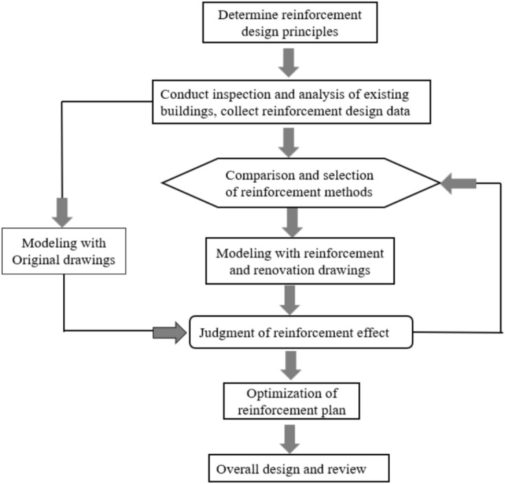
Strengthening design flow chart.
Analysis of structural defects
Analyze the repaired model using the YJK software and find the following key issues:
The overall structural story drift ratio is greater than 1/800, and the displacement ratio exceeds 1.4.
Insufficient bearing capacity of beams and columns in the original structure.
The axial compression ratio of some frame columns on the bottom floor does not meet the requirements.
Scheme comparison for structural strengthening
In response to the above issues, compare three feasible schemes:
The traditional strengthening plan, the method of increasing the column section and the structural peripheral beam section is adopted to improve overall indicators, which requires increasing the bottom floor column section from 800 × 800 to 900 × 900 mm, and increasing the peripheral beam section from 350 × 750 to 350 × 900 mm. This plan affects the layout and facade effect of the building, so it is not applicable to this project.
Adopting the technology for seismic isolation technology of building structure to strengthening36–39, using foundation isolation, and setting up seismic isolation interface, but this technology requires high requirements, long construction period, and high cost. Due to the strict cost requirements of this project, this plan is not applicable to this project.
Adopting the technology for seismic energy dissipation of building structure to strengthening, a herringbone or V-shaped buckling constraint support is set in the middle span of the Y-direction to adjust the stiffness and torsion of the structure. This plan has a small impact on the building and meets the cost requirements, so this plan is adopted.
Strengthening design
Energy dissipation strengthening design
The strengthening design process of energy dissipation is shown in Fig. 3, which has the following advantages:
Improve stiffness (lateral and torsional resistance) without changing the original structural design control parameters (such as story drift ratio).
Increase damping to reduce the seismic effect of the main structure, was shown in Fig. 4.
Reduce strengthening workload.
Fig. 3.

Energy dissipation technology strengthening design process.
Fig. 4.

Response spectrum curves with different damping ratios.
The arrangement of the vibration reduction device
BRB is a simple, stable and widely used device that reduces the amplitude of seismic response through hysteretic energy dissipation. Mainly composed of internal core plates, external constraint sleeves, and unbonded materials, which can provide additional stiffness and damping for the structure. BRB core plates are usually composed of yield section, transition section, and elastic section, and the division area is shown in Fig. 5. The yield section is the core working unit of the core plate, which dissipates yield energy under axial tensile and compressive loads; The transition section is the connection and transition area between the yield section and the elastic section. To ensure that the end is in an elastic working state, it is necessary to smoothly transition and increase the cross-sectional area of the core plate to avoid stress concentration; The elastic section is located at the end of the core plate, and its main function is to ensure stable connection with the frame beam column node area. Its connection methods include welding, bolt connection, and pin shaft connection40. During the design process, the required yield bearing force and stiffness are mainly achieved by adjusting the proportion of the area and length of each section.
Fig. 5.
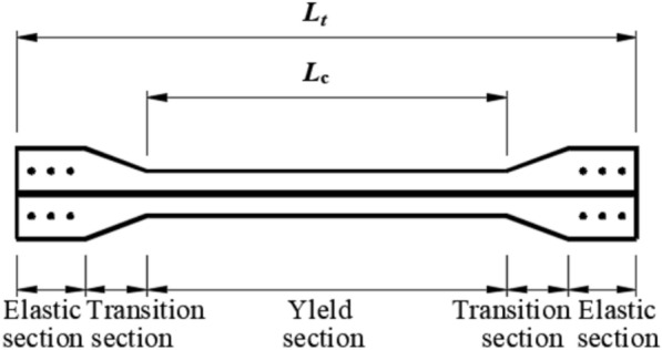
BRB core unit construction.
The selection and arrangement of vibration reduction devices
The Buckling-restrained brace (BRB) can provide stiffness for the structure. Through the calculation by the YJK software, the parameters and quantity of the energy dissipation and vibration reduction devices are determined, as shown in Table 1.
Table 1.
Design parameters of BRB.
| BRB Type | BRB1-1 | BRB1-2 | BRB1-3 | BRB1-4 |
|---|---|---|---|---|
| Core material grade | 235 | 235 | 235 | 235 |
| Yield bearing capacity/kN | 4000 | 4000 | 4000 | 4000 |
| Length/mm | 2800 | 3000 | 3200 | 3600 |
| The width of the outer sleeve/mm | 250 | 250 | 250 | 250 |
| The height of the outer sleeve/mm | 250 | 250 | 250 | 250 |
| Quantity | 4 | 80 | 12 | 8 |
According to the calculation results of the YJK software, when arranging the Buckling-restrained braces, it is known that the structural requirements for seismic reduction in the X-direction have been met. To avoid waste, BRBs were not arranged in the X-direction. Since the stiffness in the Y-direction was insufficient and the displacement was too large, BRBs were arranged in the Y-direction. As arranging one bay could meet the requirements, they were placed in the middle bay of the Y-direction. When arranging the BRBs in the Y-direction of the structure, the principles of "even distribution, dispersion, and symmetry" were followed. The arrangement positions are shown in Fig. 6.
Fig. 6.

Plan layout of BRB.
BRB layout details
Comprehensive consideration should be given to factors such as the on-site layout, lifting capacity, and installation conditions. In combination with different structural components such as reinforced concrete and steel structures, determine the size of embedded parts and connection plates, the joint forms of different components, and the embedding methods. The elevation layout of BRB is shown in Fig. 7. The connection details between BRB and existing structural components are shown in Figs. 8 and 9. At the concrete beam-column joints, a bolt-connection method is adopted. At the concrete beam-column steel-encased joints, there are 14 M20 8.8-grade chemical anchor bolts (with an anchorage depth of ≥ 175) and 12 M20 through-bolts. At the steel-encased joints in the concrete beams, 36 M20 through-bolts are arranged. During the installation of relevant components, ensure a firm connection to guarantee the reliable connection between BRB and the concrete structure, so as to meet the structural stress performance.
Fig. 7.

Elevation layout of BRB.
Fig. 8.
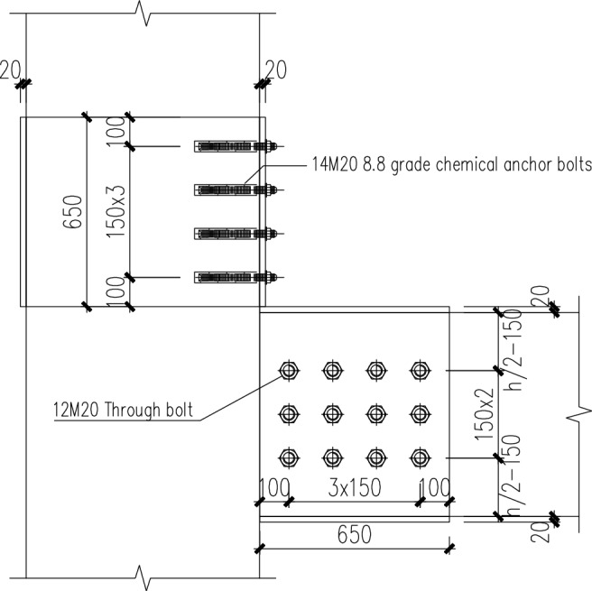
Detailed view of the steel-encased joint at the concrete beam-column connection.
Fig. 9.

Detail of the steel-encased joint within the concrete beam.
Strengthening model establishment
The structure was strengthened by using energy dissipation and vibration reduction technology, and buckling-restrained braces were set in the middle span in the Y direction. The model after strengthening is shown in Fig. 10.
Fig. 10.
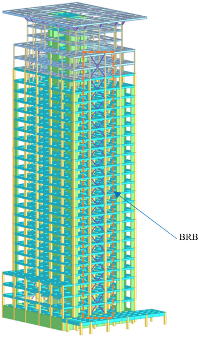
Reinforced model. Create software: YJK4.1.1, https://www.yjk.cn/.
Design results
Compare and analyze the reinforced model with the renovated model, and the results are shown in Fig. 11 and Tables 2, 3 and 4.
Fig. 11.

Story stiffness ratio.
Table 2.
Displacement ratio.
| Direction | Maximum displacement ratio | Story | Maximum interlayer displacement ratio | Story |
|---|---|---|---|---|
| X + | 1.08 | 4 | 1.09 | 3 |
| X − | 1.10 | 3 | 1.12 | 2 |
| Y + | 1.13 | 3 | 1.14 | 2 |
| Y − | 1.12 | 4 | 1.13 | 3 |
Table 3.
Natural periods and vibration modes.
| Mode shape | original structure | strengthened structure | ||
|---|---|---|---|---|
| period | Characteristics | period | Characteristics | |
| The first mode | 2.92 | Y-direction translation | 2.61 | Y-direction translation |
| The second mode | 2.45 | X-direction translation | 2.44 | X-direction translation |
| The third mode | 2.11 | twisting | 1.84 | twisting |
Table 4.
Story drift ratio.
| Structure type | Maximum story drift ratio | Direction | Story |
|---|---|---|---|
| Original structure | 1/967 | X | 18 |
| Strengthened structure | 1/990 | X | 18 |
| Original structure | 1/569 | Y | 27 |
| Strengthened structure | 1/769 | Y | 29 |
After comprehensively considering several solutions in terms of the impact on the original structure’s architectural functions, economic efficiency, and construction period, the Buckling-restrained brace strengthened structure was adopted. This approach has no impact on the building space and significantly reduces the economic cost. In terms of seismic performance, after the BRB is installed, the first few natural vibration periods of the structure are all reduced, and the maximum inter-story drift ratio is also reduced to meet the requirements of the Technical Specification for Concrete Structures of Tall Buildings in China. Moreover, the strengthened structure reduces the material usage to a certain extent.
Design of bearing capacity of energy dissipation substructure
The design process of the energy dissipation substructure is illustrated in Fig. 12. The energy-dissipating sub-structure is composed of the beams and columns connected to the BRB. The substructure has been developed with the following performance objectives: for the columns, to maintain mid-earthquake elasticity; for the beams, to achieve medium earthquake shear elasticity while preventing bending yielding. Additionally, there is an objective to enhance the seismic resistance level of the substructure from Level One to a Special Level One.
Fig. 12.

Design process of energy dissipation substructure.
Energy dissipation substructure based on the aforementioned performance goals indicates that the beam stirrups and longitudinal bars do not satisfy the required standards, while the column longitudinal bars fail to meet the minimum reinforcement ratio requirements. Consequently, both beams and columns necessitate reinforcement. Given that the increase in beam reinforcement value is less than 40% of the original reinforcement amount, adhesive steel reinforcement will be employed for this purpose. In contrast, external steel reinforcement will be utilized for column enhancement. The corresponding reinforcement diagrams are presented in Figs. 13 and 14; details regarding beam and column reinforcements can be found in Figs. 15 and 16. Additionally, scene photographs are provided in Fig. 17.
Fig. 13.

Schematic diagram of beam bonding steel reinforcement.
Fig. 14.

Schematic diagram of column reinforcement.
Fig. 15.

Drawing of beam reinforcement.
Fig. 16.

Drawing of column reinforcement.
Fig. 17.

Scene picture.
Elastic time-history analysis
Time history analysis should meet the following conditions when selecting waves:
The average seismic impact coefficient curve of multiple sets of seismic time history curves should be statistically consistent with the seismic impact coefficient curve used in the mode decomposition response spectrum method;
The effective duration of seismic waves should not be less than 5 times the period and should be greater than 15 s;
The maximum peak value of seismic waves should meet the regulatory requirements.
According to China’s seismic design requirements of "no damage under minor earthquakes, repairable under moderate earthquakes, and no collapse under major earthquakes", this analysis is aimed at frequent earthquakes, with the corresponding seismic fortification intensity being Grade 8. The peak ground accelerations of the selected seismic waves should all meet this level (PGA = 0.07 g) to be in line with the actual seismic actions. The characteristic periods of the seismic waves need to match the actual site class. In this study, the selected natural waves are all for moderately stiff sites to ensure that the spectral characteristics are consistent with the engineering site conditions. Two natural waves and one artificial wave were selected for supplementary calculations of the renovated model [Chi-Chi, Taiwan-04_NO_2743, Tg (0.39), Chi-Chi, Taiwan-04_NO_2717,Tg (0.40) and Art Wave-RH2TG040,Tg (0.40)] and reinforced model [Manjil, Iran_NO_1639,Tg (0.42),Borrego Mtn_NO_40,Tg (0.40) and Art Wave-RH3TG040,Tg (0.40)] under frequent seismic effects. The peak acceleration in the main direction of seismic waves is 70 cm/s2, and the peak acceleration in the secondary direction is 59.5 cm/s2. Figures 18 and 19 show the comparison between the selected seismic waves and the standard response spectra.
Fig. 18.

Acceleration spectra of ground motions (Renovated model).
Fig. 19.

Acceleration spectra of ground motions (Reinforced model).
Elastic time-history analysis results
Perform an elastic time-history analysis on both the renovated and reinforced models. Seismic excitation was applied in both horizontal directions, with a peak acceleration ratio of seismic waves in the X and Y directions set at 1:0.85. The results of the elastic time-history analysis for the reinforced model are presented below. Figures 20 and 21 illustrate the story drift ratio curves obtained from the elastic time-history analysis, while Figs. 22 and 23 depict the story acceleration curves.
Fig. 20.

Comparison of elastic time history story drift ratio (Renovated model).
Fig. 21.

Comparison of elastic time history story drift ratio (Reinforced model).
Fig. 22.

Comparison of elastic time history floor accelerations (Renovated model).
Fig. 23.

Comparison of elastic time history floor accelerations (Reinforced model).
From these figures, it is evident that the story drift ratio calculated using the elastic time-history method for the renovated model exceeds the allowable limit of 1/800; conversely, the results for the reinforced model comply with specification requirements. Additionally, it can be observed that the floor acceleration of the reinforced model is lower than that of its renovated counterpart.
According to Article 4 of Article 4.3.5 of the Technical specification for concrete structures of tall buildings in China and Article 5.1.2 of the Code for seismic design of buildings in China, when three sets of time history curves are taken for analysis, the seismic effect of the structure can be taken as the larger value of the envelope value of the time-history method and the vibration mode decomposition response spectrum method. In the strengthening design, the envelope values of time history analysis and CQC are used for envelope.
Static elastic–plastic analysis
This project conducts static elastic–plastic analysis (pushover analysis) of the entire structure under rare earthquake action, calculates the capacity curve of the structure, determines the performance points of the structure, and checks whether the estimated elastic–plastic story drift ratio of the structure under rare earthquake action meets the specification requirements.
Pushover analysis is an important tool for implementing displacement-based seismic design (DBSD) and performance-based seismic design (PBSD).
The pushover analysis method is to apply a distributed form of lateral force along the height of the structure, gradually increasing the lateral force until the structural control point reaches the target displacement or the structure overturns. After obtaining the load–displacement curve through pushover analysis, it is combined with the response spectrum to use the capacity spectrum method (CSM) recommended by ATC-40 to find the equivalent lateral load to seismic action, and finally find the performance point (ATC-40 uses the bearing capacity spectrum method to first establish a 5% damping linear elastic response spectrum, then use energy dissipation effect to reduce the response spectrum value and estimate the nonlinear displacement of the structure).
The capacity spectrum method is to draw the capacity spectrum and the demand spectrum representing a certain seismic level in the same coordinate system. The intersection point of the two curves is the performance point, which reflects the seismic performance of the structure under this seismic level. The recorded ground vibration acceleration response spectrum or the response spectrum recommended by the standard is converted from the acceleration period form to the acceleration displacement spectrum form (Sa-Sd curve) to obtain the demand spectrum; The capacity spectrum is converted from the Pushover capacity curve to the acceleration displacement spectrum curve (Sa-Sd curve) under an equivalent single degree of freedom system. The results are shown in Fig. 24.
Fig. 24.

Capacity spectrum and demand spectrum curve.
Perform static elastic–plastic analysis on the structure, with a maximum seismic impact coefficient of 0.9 and a characteristic period of 0.45.
The maximum story drift ratio corresponding to rare earthquake performance points in the X + , X −, Y + , and Y-directions are 1/122, 1/138, and 1/122, 1/120, respectively, all less than 1/100. The relevant indicators at the rare earthquake performance control points are shown in Table 5.
Table 5.
The indicators of Performance point.
| Direction | Maximum story drift ratio | Story | Equivalent damping ratio (%) |
|---|---|---|---|
| X + | 1/122 | 11 | 14.82 |
| X − | 1/138 | 12 | 14.13 |
| Y + | 1/122 | 17 | 14.49 |
| Y − | 1/120 | 17 | 14.34 |
Conclusions
Problem statement
This study addressed the seismic retrofit challenges of a 24-story high-rise building originally designed to 2001 Chinese seismic codes (GB 50011-2001). The structure exhibited three critical deficiencies after functional modifications:
Excessive torsional response.
Insufficient column axial capacity.
Exists weak-story mechanism.
Methodological approach
The research implemented a systematic performance-based retrofit strategy:
Problem analysis: Pushover analysis and time-history analysis were carried out using YJK software to quantify the structural deficiencies.
Solution screening: Three retrofit solutions were evaluated through the following aspects: the impact on the original structure, technical feasibility, economic efficiency, and seismic performance. Finally, it was chosen to arrange buckling-restrained braces in the middle span of the structural Y direction.
Main achievements
This project is designed for seismic fortification at an intensity of 8 degrees. The BRB provide additional stiffness to the structure under minor earthquakes, and additional damping under moderate and major earthquakes, endowing the structure with good seismic performance. The calculation results meet the requirements of relevant codes. Under frequently-occurring earthquakes, the structure can remain in the elastic state, and the main indexes such as floor shear force, inter-story drift ratio, and torsional displacement ratio all meet the requirements specified in the codes.
The present study conducts elastic time history analysis and static elastic–plastic analysis on an overall model of the structure with added buckling-restrained braces (BRB). Under rare seismic events, the maximum story drift ratio in both X and Y directions remain below 1/100 after the installation of BRBs. The structure demonstrates excellent seismic performance, achieving the objective of "no collapse under rare earthquakes".
Buildings equipped with BRB exhibit distinct advantages compared to structures designed under modern codes in several aspects:
BRB can enhance stiffness without significantly increasing weight, whereas modern code-compliant structures often require heavier members. BRB demonstrate stable hysteretic behavior, concentrating energy dissipation within themselves while offering excellent cumulative plastic deformation capacity, thereby effectively protecting primary structural components. In contrast, modern code-based structures rely on global ductility and are prone to strength degradation. BRB localize damage and allow easier post-earthquake repairs, while modern code-compliant structures suffer dispersed damage, making repairs more challenging. BRB retrofitting is cost-effective and minimally disruptive to buildings, whereas modern code-conforming structures entail higher material costs and may reduce usable space. BRB-equipped buildings exhibit higher collapse safety margins and lower sensitivity to long-duration earthquakes compared to traditional braced frames. Modern code-based structures are more vulnerable, with critical member failures posing a higher risk of progressive collapse.
Author contributions
Shengzhi Shi: Conceptualization, Methodology, Writing-Original draft preparation. Li Xin: Supervision, Writing-Review and Editing. Chao Huang: Investigation, Formal analysis. Gangqi Han: Investigation, Methodology. Zhaodong XU: Conceptualization, Supervision, Writing-Review and Editing. Xinyu Chen: Investigation, Data management. All authors reviewed the manuscript.
Data availability
The datasets used and/or analyzed during the current study are available from the corresponding author on reasonable request.
Declarations
Competing interest
The authors declare no competing interests.
Footnotes
Publisher’s note
Springer Nature remains neutral with regard to jurisdictional claims in published maps and institutional affiliations.
Contributor Information
Shengzhi Shi, Email: 375566971@qq.com.
Li Xin, Email: xinli1129@sina.com.
References
- 1.Li, Q. Q. et al. Hyper elastic hybrid molecular chain model of thermal-oxidative aging viscoelastic damping materials based on physical–chemical process. J. Eng. Mechan.149(1), 04022099 (2023). [Google Scholar]
- 2.Li, H. W. et al. Development and validation of a nonlinear model to describe the tension–compression behavior of rubber-like base isolators. J. Eng. Mechan.149(2), 04022104 (2023). [Google Scholar]
- 3.Zhao-Dong, X., Ge, T. & Liu, J. experimental and theoretical study of high-energy dissipation-viscoelastic dampers based on acrylate-rubber matrix. J. Eng. Mechan.10.1061/(ASCE)EM.1943-7889.0001802 (2020). [Google Scholar]
- 4.Dong, Y. R. et al. Tests and micro–macro cross-scale model of high-performance acrylate viscoelastic dampers used in structural resistance. J. Struct. Eng.149(7), 04023088 (2023). [Google Scholar]
- 5.Zhao Dong, X., Liao, Y. X., Ge, T. & Chao, X. experimental and theoretical study of viscoelastic dampers with different matrix rubbers. J. Eng. Mechan.10.1061/(ASCE)EM.1943-7889.0001101 (2016). [Google Scholar]
- 6.Dong, Y. R. et al. Design parameters and material-scale damage evolution of seismic upgraded RC frames by viscoelastic haunch bracing-dampers. J. Earthq. Eng. Struct. Dyn.50(5), 1476–1491 (2021). [Google Scholar]
- 7.Dong, Y.-R. et al. Experimental study on viscoelastic dampers for structural seismic response control using a user-programmable hybrid simulation platform. J. Eng. Struct.216, 110710 (2020). [Google Scholar]
- 8.Xu, Z. D. et al. Experimental and theoretical study on a building structure controlled by multi-dimensional earthquake isolation and mitigation devices. J. Nonlinear Dyn.89, 723–740 (2017). [Google Scholar]
- 9.Xu, Z.-D., Qing, Tu. & Guo, Y.-F. Experimental study on vertical performance of multidimensional earthquake isolation and mitigation devices for long-span reticulated structures. J. Vibration Control18(13), 1971–1985 (2012). [Google Scholar]
- 10.Yang, Y. et al. Cross-scale integrated optimization of control system with multiple MR dampers for spatial torsional vibration mitigation. J. Mechan. Syst. Signal Process.229, 112514 (2025). [Google Scholar]
- 11.Liu, X. Y. et al. Seismic response analysis of three-dimensional base isolation structures considering rocking and P-Δ effects. J. Eng. Struct.328, 119689 (2025). [Google Scholar]
- 12.Tao, Y et al. Integrating deep learning into an energy framework for rapid regional damage assessment and fragility analysis under Mainshock‐aftershock sequences. J. Earthq. Eng. Struct. Dyn. (2025).
- 13.Yeshou, X. et al. Investigation of the dynamic properties of viscoelastic dampers with three-chain micromolecular configurations and tube constraint effects. J. Aerospace Eng.10.1061/JAEEEZ.ASENG-5141 (2025). [Google Scholar]
- 14.Hu, Z. W. et al. Full-scale shaking table test on a precast sandwich wall panel structure with a high-damping viscoelastic isolation and mitigation device. J. Eng. Struct.329, 119797 (2025). [Google Scholar]
- 15.Ty. Experimental study on shear wall with braces. J. Struct. Design Tall Special Build. 24 (1), 73–95 (1971).
- 16.Nakamura, H., Takeuchi, T., Maeda, Y et al. Fatigue properties of practical-scale unbonded braces. J. Nippon Steel Technical Report.82(0), (2000).
- 17.Mazzolani, F. M. Innovative metal systems for seismic upgrading of RC structures. J. Construct. Steel Re-search.64(7–8), 882–895 (2008). [Google Scholar]
- 18.Tsaic, S. A study of buckling restrained seismic braced frame. J. Struct. Eng.17(22), 3–32 (2002). [Google Scholar]
- 19.Black, C. J., Makris, N. & Aiken, I. D. Component testing, seismic evaluation and characterization of buckling-restrained braces. J. Struct. Eng.130(6), 880–894 (2004). [Google Scholar]
- 20.Fahnestock, L. A., Ricles, J. M. & Sause, R. Experimental evaluation of a large-scale buckling-restrained braced frame. J. Struct. Eng.133(9), 1205–1214 (2007). [Google Scholar]
- 21.Chou, C. C., Liu, J. H. & Pham, D. H. Steel buckling-restrained braced frames with single and dual corner gusset connections: Seismic tests and analyses. J. Earthq. Eng. Struct. Dyn.41(7), 1137–1156 (2012). [Google Scholar]
- 22.Güneyisi, E. M. Seismic reliability of steel moment resisting framed buildings retrofitted with buckling restrained braces. J. Earthq. Eng. Struct. Dyn.41(5), 853–874 (2012). [Google Scholar]
- 23.Guneyisi, E. M., Tunca, O. & Azez, I. Nonlinear dynamic response of reinforced concrete building retrofitted with buckling restrained braces. J. Earthq. Struct.8(6), 1349–1362 (2015). [Google Scholar]
- 24.Usami, T., Wang, C. & Funayama, J. Low-cycle fatigue tests of a type of buckling restrained braces. J. Procedia Eng.14, 956–964 (2011). [Google Scholar]
- 25.Higgins, C. & Newell, J. Confined steel brace for earthquake resistant design. J. Eng. J. AISC.41(4), 187–202 (2004). [Google Scholar]
- 26.Brown, P., Aiken, I. D. & Jafarzadeh, F. J. Seismic retrofit of the Wallace F. Bennett Federal Building. J. Modern Steel Construct.41(8), 29–39 (2001). [Google Scholar]
- 27.Wang, C., Usami, T. & Funayama, J. Improving low-cycle fatigue performance of high-performance buckling-restrained braces by toe-finished method. J. Earthq. Eng.16(8), 1248–1268 (2012). [Google Scholar]
- 28.Matsui, R, Takeuchit. Effect of local buckling of core plates on cumulative deformation capacity in buckling restrained braces. In: Proc. of the 7th International Conference.Japan: Behaviour of Steel Structures in Seismic Areas, 607–613, (2012).
- 29.Almeida, A. et al. Seismic retrofit of RC building structures with buckling restrained braces. J. Eng. Struct.130, 14–22 (2017). [Google Scholar]
- 30.Barbagallo, F. et al. A multi-performance design method for seismic upgrading of existing RC frames by BRBs. J. Earthq. Eng. Struct. Dyn.46(7), 1099–1119 (2017). [Google Scholar]
- 31.Du, K. et al. Seismic performance quantification of buckling-restrained braced RC frame structures under near-fault ground motions. J. Eng. Struct.211, 110447 (2020). [Google Scholar]
- 32.Castaldo, P. et al. Seismic performance of an existing RC structure retrofitted with buckling restrained braces. J. Build. Eng.33, 101688 (2021). [Google Scholar]
- 33.Li, C. et al. A procedure for assessing low-cycle fatigue life of buckling-restrained braces. J. Struct. Eng.148(2), 4021259 (2022). [Google Scholar]
- 34.Rafi, M. M. et al. Experimental investigation of dynamic behavior of RC frame strengthened with buckling-restrained bracing. J. Struct. Eng.148(7), 04022076 (2022). [Google Scholar]
- 35.Bouderradji, M., Dimia, M. S. Lahbari, N. The Impact of Buckling Restrained Braces in Strengthening Deficient Reinforced Concrete Structures. J. Int. J. Struct. Stability Dyn.2024, 2550202 (2024).
- 36.De Luca, A. et al. Base isolation for retrofitting historic buildings: Evaluation of seismic performance through experimental investigation. J. Earthq. Eng. Struct. Dyn.30(8), 25–1145 (2001). [Google Scholar]
- 37.Matsagar, V. A. & Jangid, R. S. Base isolation for seismic retrofitting structures. J. Practice Periodical Struct. Des. Construct.13(4), 175–185 (2008). [Google Scholar]
- 38.Cardone, D. & Flora, A. An alternative approach for the seismic rehabilitation of existing RC buildings using seismic isolation. J. Earthq. Eng. Struct. Dyn.45(1), 91–111 (2016). [Google Scholar]
- 39.Natale, A., Del Vecchio, C. & Di Ludovico, M. Seismic retrofit solutions using base isolation for existing RC buildings: Economic feasibility and pay-back time. J. Bull. Earthq. Eng.19(1), 483–512 (2021). [Google Scholar]
- 40.An, N. Investigation on the seismic performance of parallel double-stage yielding buckling restrained brace-frame structures. J. Beijing Univ. Civ. Eng. Architecture. 2023 (in Chinese).
Associated Data
This section collects any data citations, data availability statements, or supplementary materials included in this article.
Data Availability Statement
The datasets used and/or analyzed during the current study are available from the corresponding author on reasonable request.