

Abstract
This study examines the effect of thermal radiation on nanofluid flow and heat transfer over a truncated cone in the presence of pressure work, a problem critical for thermal management and industrial cooling systems. Using similarity transformations, the governing equations are converted into coupled nonlinear partial differential equations and solved numerically via the Legendre collocation method. It gives a high degree of consistency between the proposed numerical solutions and the results previously reported under specific cases. The Prandtl number, pressure work parameter, radiation parameter, and nanoparticle volume fraction all have a major impact on flow and thermal behavior, according to the main results. Nanofluids enhance the transfer of heat by 10–40% when compared to pure fluid, cooling speeds up, and surface strength and hardness improve. Also, the kinds of nanofluid and the parameters related to the volume percentage of nanoparticles are crucial in determining the flow behavior. The surface mechanical properties are advanced by using 10% nanoparticle nanofluid rather than 5%. It has been discovered that the strength and hardness of the surface will enhance with an increase in the pressure work parameter when employing Cu-water nanofluid, but they will decrease with an increase in the thermal radiation parameter values. The novelty of this work lies in the application of the Legendre collocation method to this problem, along with new quantitative insights into how pressure work and radiation interact with nanofluids, providing practical guidelines for optimizing thermal and mechanical performance in industrial systems.
Supplementary Information
The online version contains supplementary material available at 10.1038/s41598-025-10554-5.
Keywords: Thermal radiation, Vertical truncated cone, Laminar boundary layer, Pressure work, Nanofluid, Legendre collocation method
Subject terms: Applied mathematics, Fluid dynamics
Introduction
Convection flow research is essential to many scientific and industrial fields, such as sophisticated thermal management systems, nuclear reactor cooling, and star and planet formation. For engineering solutions to be optimized, it is crucial to comprehend temperature distribution and heat transfer, especially when pressure work and free convection are involved. Even though natural convection along vertical surfaces has been thoroughly investigated, configurations involving thermal radiation, non-uniform surface temperatures, and nanofluids are still being researched because of their potential to greatly improve heat transfer efficiency in energy applications and cooling systems1–11.
The foundation for comprehending these systems was established by early studies of convection flows across conical geometries. General laws for analogous solutions on isothermal axisymmetric shapes, such as vertical cones, were established by Merk and Prins12,13. Roy14 expanded the work to high Prandtl number fluids, whereas Hering and Grosh15 investigated laminar free convection from non-isothermal cones at low Prandtl numbers. In more recent studies, laminar free convection from vertical circular cones with non-uniform surface temperatures and pressure work was studied by Alim et al.16 and Alam et al.17. These investigations’ relevance to sophisticated heat transport situations was limited, though, because they did not completely address thermal radiation or nanofluids.
By examining natural convection boundary layer flow over a truncated cone embedded in a porous medium saturated by a nanofluid with constant wall temperature and nanoparticle volume percent, Cheng18 made a substantial contribution to the field of truncated cone research. In this study, thermophoresis and Brownian motion were included. It was discovered that although lowering the buoyancy ratio or Lewis number raises the local Nusselt number, raising these parameters decreases it. It did not, however, include heat radiation or pressure work, which are essential for solar energy systems and electronic cooling, for example. Noghrehabadi et al.19 studied the natural-convection flow of nanofluids over vertical cone embedded in non-darcy porous media. Sayed and Fathy20 studied the upward cone flow of nanofluids and the effects of thermal radiation and heat generation on heat transfer. A powerful, consistent transverse magnetic field perpendicular to the cone surface is applied to the flow.
Recent research has begun to explore thermal radiation in nanofluid flows. For instance, Ragulkumar et al.21 investigate the MHD water-based nanofluid flow via an upright cone. The heat and mass flux pattern is used in this mathematical model to examine MHD, viscous dissipation, radiation, chemical reactions and suction/injection processes. Vinutha et al.22 examined the influence of a magnetic field on nanofluid passing through a cone and wedge with mass and heat transmission.. While this study advances the understanding of nanofluid behavior under thermal radiation, it focuses on vertical cones rather than truncated cones and does not address pressure work, leaving a gap in the literature for truncated cone-specific configurations.
Despite these advancements, the combined effects of pressure work, thermal radiation, and nanofluids on convection flow over a truncated cone remain underexplored. Studies like Cheng18, and Noghrehabadi et al.19 provide valuable insights into truncated cone configurations but do not address the interplay of all three factors pressure work, thermal radiation, and nanofluids. Similarly, Sayed and Fath20 highlight the importance of thermal radiation but focus on vertical cones without considering pressure work or truncated cone geometries.
This study introduces key innovations, including a comprehensive analysis of pressure work’s influence on free convection in a nanofluid, the incorporation of thermal radiation effects using a nonlinear temperature model, and a comparative assessment of different nanofluid types to optimize heat transfer performance. Notably, the Legendre collocation method, which is a high-precision numerical approach not previously applied to this class of problems, is implemented to solve the governing equations, providing superior accuracy in capturing boundary layer dynamics and heat transfer characteristics. By addressing these gaps, our work provides new insights into advanced thermal systems, contributing to applications in nuclear cooling, aerospace engineering, and nanofluid-based heat exchanger design.
The governing equations and mathematical formulation
Laminar free convection flow in two dimensions via a truncated cone will be examined in a steady state. Given that  is the coordinate normal to the surface of the cone and
  represents the position along the cone’s surface as measured from the origin, the physical coordinates
  are selected so that the coordinates’ origin is at the cone’s vertex.
  is a measurement of the truncated cone’s leading edge’s distance from the origin. Figure 1 displays the flow setup and coordinate system. Copper Cu, silver Ag, and titanium TiO2 are among the many nanoparticles present in the water-based nanofluid. The assumption is that there is no slip between the nanoparticles and the base fluid and that they are in thermal equilibrium.
Fig. 1.
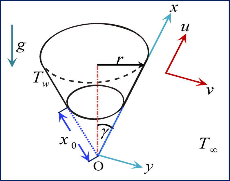
Coordinate system and physical model.
Using a vertical cone, the following boundary layer governing equations16,23:
 |
1 |
 |
2 |
 |
3 |
The boundary conditions are provided by
 |
4 |
where  and
and  represent the fluid velocity components in the
  and
and  directions, respectively, and
  is the cone’s radius. In this case,
  ,
,  ,
,  and
and  stand for the nanofluid’s dynamic viscosity, density, coefficient of thermal expansion coefficient of nanofluid, and specific heat at constant pressure, respectively.
  is the acceleration caused by gravity,
  is the temperature of the nanofluid,
  is the ambient temperature,
  is the temperature of the cone surface,
  is the nanofluid’s thermal conductivity, and
  is the cone apex half angle. Table 1 provides the nanoparticles’ thermophysical properties20,24,25. Table 2 introduces the thermophysical properties of nanofluids: Cu, Ag, TiO2 and water at 5% nanoparticle volume fraction (25 °C)26–29. A Cu–water nanofluid’s normalized thermo-physical characteristics are shown in Fig. 2 as the concentration of nanoparticles rises from 0 to 10%. There is a noticeable improvement in thermal conductivity, which suggests improved heat transmission capacity. Additionally, viscosity rises, which may increase the need for pumping power and flow resistance. With the addition of more Cu nanoparticles, density increases linearly and the specific heat decreases.
Table 1.
Water and nanoparticle thermophysical properties.
 |
 |
 |
 |
|
|---|---|---|---|---|
 |
997.1 | 4179 | 0.6130 | 21.0 |
 |
8933 | 385.0 | 401.00 | 1.67 |
 |
10,500 | 235.0 | 429.00 | 1.89 |
 |
4250 | 686.2 | 8.9538 | 0.90 |
Table 2.
Thermophysical properties of nanofluids: Cu, Ag, TiO2 and water at 5% nanoparticle volume fraction (25 °C).
| Property | Base Fluid (Water) | Cu-Water Nanofluid |
Ag-Water Nanofluid |
TiO2-Water Nanofluid |
|---|---|---|---|---|
Thermal Conductivity 
|
0.613 | 0.74 | 0.85 | 0.71 |
Density 
|
997 | 1385 | 1475 | 1162 |
Specific Heat 
|
4179 | 3650 | 3550 | 3850 |
Fig. 2.
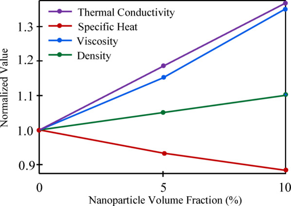
Normalized thermophysical properties of Cu–water nanofluid the versus nanoparticles concentration.
We can define the hydrostatic pressure under external conditions as  , and using the radiation Rosseland approximation30, the radiative heat flux,
  , may be expressed simply as
 |
5 |
where  and
and  stand for the mean absorption coefficient and Stefan-Boltzmann constant, respectively. To state the term
  to be as a linear function of temperature, we assume that the temperature gradients within the flow are sufficiently large. Therefore, by ignoring higher-order terms and extending
  in a Taylor series around
  , it becomes
 |
6 |
Equations (5) and (6) are used to transform the energy Eq. (3) into
 |
7 |
The following are the characteristics of the nanofluid.
 |
8 |
It should be noted that when  , the study drops to those of a viscous or ordinary fluid, where
  is the volume percentage of nanoparticles. The following kinds of similarity hold for the Eqs. (1), (2) and (7) under condition Eq. (4):
 |
 |
9 |
In the boundary layer region, the functions  and
and  represent the stream function and the temperature function of the fluid, respectively, in dimensionless form, while
  is the local Grashof number and
  is the pseudo-similarity variable. The definitions of
  and
and  that fulfill Eq. (1) are
  and
and  , if
, if  is the stream function. The preceding nonlinear partial differential equations system were produced by replacing the transformations provided in Eq. (9) into Eqs. (2), (4), and (7):
 |
10 |
 |
11 |
subject to the following boundary conditions:
 |
12 |
Here, the differential with regard to  is indicated by the primes,
  indicates the Prandtl number,
  for radiation parameter, and
  for pressure work parameter, which Gebhart31 was the first to employ.
The two most important components of the flow from an engineering perspective are the skin friction coefficient and the Nusselt number, which stand for heat transfer rate and surface shear stress, respectively. The mechanical properties of the surface are directly impacted by these characteristics throughout the heat treatment process. For example, when the heat transfer rate, heat flux, increases at the material surface, the cooling speed arises. Therefore, it enhances the surface’s shear strength and hardness while decreasing its ductility, which raises the risk of surface cracking. The surface shear stress  , the skin friction coefficient
  , surface heat flux
  and the Nusselt number
  are given as:
 |
 |
13 |
 |
14 |
where  is the reference velocity.
Legendre polynomials
The first kind of Legendre polynomial,  , of degree
  is generated when the Legendre differential equation is solved. It is defined by32:
 |
15 |
where  with recurrence relations33
 |
16 |
 |
17 |
Lemma 1
33,34
Let
 with
with
 , where
 and
and
 are Sobolev spaces on the domain
 . Let
. Let
 be the bivariate Legendre interpolant of
 at Legendre nodes on the interval
 , Then, the following error estimates hold:
- Interpolation Error in the
 -Norm:
18 - Error in Approximating the
 -th Derivative:
and
19 
20
Mathematical formulation via Legendre collocation method
To solve the system (10)–(12) using egendre-collocation technique35, the solution domain should transformed from  or
or  to the interval
  . Hence, the linear transformations
  and
and  , where
  are applied. This yields the following coupled system:
 |
21 |
 |
22 |
with the boundary conditions
 |
23 |
To solve the system (21)–(23), it is necessary to use the following transformation:
 |
24 |
 |
25 |
 |
26 |
with the boundary conditions
 |
27 |
Assume that the Legendre polynomials of the nonlinear system (21)–(23) provide the following approximate solution for the unknowns function:
 |
 |
 |
28 |
By substituting into the system and applying the collocation approach, results:
 |
29 |
 |
 |
 |
30 |
 |
 |
 |
31 |
with the boundary conditions
 |
 |
32 |
Where  . When combined the conditions (32) with the nonlinear system (30) and (31), the system matrix form is
 |
33 |
 |
 |
 |
 |
 |
 |
 |
 |
 |
 |
 |
 |
 |
 |
 |
In the nonlinear system (33), C, D and E are the unknowns. We’ll apply Newton’s method to solve resulting nonlinear system that has  equations with a tolerance of
  . Convergence was verified by increasing the number of collocation points
  until the residual error fell below
  . Once the system has been resolved, the values of the unknowns are known. To solve our problem, the inverse transformations.
 |
34 |
should be applied to obtain the tables and the graphs to introduce the physical and mechanical interpretations. All computations were performed in Mathematica 13.3 using a custom spectral collocation code, with derivatives computed via Legendre polynomial differentiation matrices.
Tables 3 and 4 demonstrate the validation of the numerical method used in this study and compare the results with other research in14,15,36–41 with  . Here,
  is indicated by
  .
.
Table 3.
Comparison of  and
and  at
at  for different Prandtl number values (0.1, 1.0, 10).


Table 4.
Comparison of  and
and  at
at  for different Prandtl number values.


Results and discussion
The Eqs. (10) and (11), which satisfy the boundary conditions in Eq. (12), have been numerically solved using the Legendre collocation method for a range of values of the involved parameters, including the Prandtl number, pressure work parameter, radiation parameter, and nanoparticle volume fraction. Figures 3, 4, 5, 6, 7, 8, 9, 10 and 11 display the effects of varying the radiation parameter, pressure work parameter, nanoparticle volume percentage, and nanoparticle type on the local skin friction, Nusselt number dimensionless temperature,  , and dimensionless velocity profiles,
  . Three distinct kinds of nanoparticles nanoparticles—Cu, Ag, and TiO2—were examined, using water as the base fluid. The components Cu, Ag, and TiO2 as well as the thermophysical properties of water are displayed in Table 1. The effects of the parameters used in this study are:
Radiation parameter
Figure 3 illustrates how changing the radiation parameter  effects on the Cu-water nanofluid’s dimensionless temperature and velocity within the boundary layer in relation to
  . It has been noted that the temperature and velocity inside the boundary layer rise with increasing
  . Physically, a higher
  causes the nanofluid to absorb more heat from radiation, which raises the fluid’s temperature and causes it to flow more quickly because of its decreased viscosity. This may result in improved heat transmission and modifications to the system’s fluid dynamics.
Fig. 3.

(a) The radiation parameter impacts on the velocity profiles  . (b) The radiation parameter impacts on the temperature
  profiles.
Figure 4 introduces how the radiation parameter affects the local skin friction coefficient and local Nusselt number for Cu nanoparticles. According to these statistics, a higher radiation parameter value increases the velocity gradient but reduces buoyancy effects by enhancing energy dissipation via radiation, leading to a decrease in the skin friction coefficient. Furthermore, increasing leads to a decrease in local Nusselt number because a portion of the heat is carried away by radiation, reducing the convective heat transfer, which indicates that the surface’s strength and hardness will decrease when thermal radiation is present.
Fig. 4.

(a) The radiation parameter affects the skin-friction coefficient. (b) The radiation parameter effects on the Nusselt number.
Pressure work parameter
The temperature and velocity profiles for the pressure work parameter in the Cu-water nanofluid scenario are displayed in Fig. 5. It is evident from these data that when  increases, the temperature and velocity profiles decline. Physically, the nanofluid becomes compressed when pressure rises, which lowers the fluid’s capacity to retain heat and causes the temperature to drop. The fluid is facing more flow resistance when the pressure gradient rises. The velocity is slowed down because the nanofluid must resist more forces to continue moving. Greater pressure gradients tend to decrease the fluid’s momentum, which means that for the fluid molecules to move, they must resist these greater pressure forces. Consequently, the boundary layer’s velocity profile falls.
Fig. 5.

(a) The pressure work parameter impacts on the velocity profiles  . (b) The pressure work parameter impacts on the temperature
  profiles.
Figure 6 shows how the pressure work parameter affects the local Nusselt number and skin friction coefficient. These numbers demonstrate that a higher-pressure work parameter results in lower skin friction coefficient values because higher-pressure work parameter can lead to a reduction in fluid viscosity (for temperature-dependent viscosity models), which may result in a lower wall shear stress and hence a lower skin friction coefficient. Furthermore, a higher-pressure work parameter results in higher local Nusselt numbers, indicating that the surface’s strength and hardness will be satisfactory when this force is present.
Fig. 6.

(a) The pressure work parameter affects the skin-friction coefficient. (b) The pressure work parameter effects on the Nusselt number.
Table 5 presents how the skin friction coefficient and Nusselt number are affected by the pressure work parameter for both truncated and full cones. In both the truncated and complete cones, the skin friction reduces and the Nusselt number increases because of raising the pressure work parameter. Compared to the full cone, the truncated cone displays a reduced rate of heat transmission due to thicker boundary layer and reduced temperature gradient. Although the skin friction coefficients of the two are almost equal, the truncated cone’s coefficient is still lower than the full cone’s coefficient due to less steep velocity gradient and delayed boundary layer.
Table 5.
Comparison of skin friction and Nusselt number for both truncated and full cone at  for different pressure work parameters.
 |
Truncated Cone | Full Cone | ||
|---|---|---|---|---|
 |
 |
 |
 |
|
 |
0.006754 | 110.9965 |  |
 |
 |
0.006731 | 126.6357 |  |
 |
 |
0.006704 | 145.7653 |  |
 |
Nanoparticle volume
Figure 7 illustrates how changing the volume percentage of nanoparticles affects the dimensionless temperature and velocity for the Cu-water nanofluid versus  . It is noted that when the value of
  grows, the temperature rises, and the velocity profiles fall. As the
  value rises, the fluid becomes more viscous. Natural convection is reduced as a result, causing the fluid to travel more slowly. The thermal boundary layer thickens because of this velocity decrease, raising the boundary layer’s internal temperature. Nanoparticles improve the effective thermal conductivity of the fluid, leading to higher temperature gradients near the heated surface and thinner thermal boundary layers due to improved heat diffusion. Generally, more nanoparticles enhance convective heat transfer and raise the temperature in the fluid.
Fig. 7.

(a) The nanoparticle volume fraction parameter impacts on the velocity profiles  . (b) The nanoparticle volume fraction impacts on the temperature
  profiles.
Figure 8 demonstrates how, in the instance of Cu nanoparticles, rising  from 5 to 10% causes the values of the temperature and velocity gradients at the surface to gradually diminish. However, when the concentration of nanoparticles in the base fluid increases, both heat transmission and skin friction increase. Therefore, it can be concluded that a nanofluid containing 10% nanoparticles has a greater impact on mechanical characteristics than one containing 5% nanoparticles. Using a nanofluid throughout the cooling process can generally improve the surface’s mechanical properties more actively. For instance, compared to pure water, the heat transfer rate is increased by 10–40% when a nanofluid is used. This accelerates the process of cooling and increases the strength and hardness of the surface.
Fig. 8.

(a) The nanoparticle volume fraction parameter affects the skin-friction coefficient. (b) The nanoparticle volume fraction parameter affects the Nusselt number.
As the volume fraction  increases, the effective viscosity
  rises according to the Brinkman model
  . The nanofluid exhibits Newtonian fluid behavior at low
  (0.05–0.10), which increases heat transfer through improved thermal conductivity
  and a slight rise in viscosity. Higher
  , on the other hand, might cause non-Newtonian, slurry-like behavior due to nanoparticle aggregation and greater particle–particle interactions. This behavior is typified by exponentially increasing viscosity, possible sedimentation, and decreased convective flow. The size, shape, density, and dispersion stability of the nanoparticles determine the threshold concentration for the slurry transition. The highest packing fraction
  for stable solutions of spherical nanoparticles (Cu, Ag, TiO2) is often between 0.20 and 0.30. Beyond this, the nanofluid has a high flow resistance and resembles a slurry. Sedimentation dangers rise with increasing phi, especially for Ag and Cu, due to the differential in densities. Due to their high densities and aggregation tendencies, Cu-water and Ag-water nanofluids may exhibit slurry-like behavior at
  , but TiO2-water, which has a lower density, may stay stable until
  . In practical applications, such as cooling systems or heat exchangers, a slurry-like nanofluid (
 > 0.20) would complicate the use of pressure work-driven convection and negate thermal gains by increasing pumping power needs and pressure losses. The skin friction and Nusselt values for
  and
and  are introduced in Fig. 9. As was said in the preceding explanation, it shows how increasing viscosity by raising
  causes the skin friction values to decrease. Conversely, an improvement in the heat transfer rate by increasing
  causes the Nusselt values to rise.
Fig. 9.

(a) The skin-friction values at  and
and  . (b) The Nusselt values at
  and
and  .
.
Nanoparticles type
The fluid temperature and velocity profiles for Cu-, Ag-, and TiO2-water nanofluids are displayed in Fig. 10. Because the mass density of Cu is smaller than Ag but more than TiO2, it is found that the addition of TiO2 nanoparticles causes the fluid to move faster, whereas Ag nanoparticles cause the fluid to move more slowly than other nanoparticles before decreasing the velocity to zero. However, as seen in Table 1, the high value of Ag’s thermal conductivity raises the fluid temperature while TiO2 nanoparticles cause it to drop.
Fig. 10.

(a) The different nanoparticle type impacts on the velocity profiles  . (b) The different nanoparticle type impacts on the temperature
  profiles.
Figure 11 makes it evident that when the nanoparticle was changed from TiO2, Cu to Ag, the velocity gradient values at the surface grew progressively. However, the reverse order of the nanoparticle type happens with the temperature gradient. Then, Ag-nanofluid has a higher skin friction and surface shear stress than Cu and TiO2-nanofluid, respectively. It also Ag -nanofluid has a higher Nusselt number and a higher rate of heat transfer from the surface than Cu and TiO2-nanofluid, respectively. These findings suggest that Ag-nanofluid is a more effective cooling medium for surface hardness and strength.
Fig. 11.

(a) The different nanoparticle type affects the skin-friction coefficient. (b) The different nanoparticle type effects on the Nusselt number.
Conclusions
This study uses three different types of nanoparticles (Cu, Ag, and TiO2) to investigate the constant, laminar-free convection of a nanofluid from a truncated cone in the presence of heat radiation and pressure work. Our study’s objective was to determine the surface’s mechanical qualities and heat transfer characteristics, and the following findings were attained:
As the radiation parameter increases and the pressure work parameter, Prandtl number, and concentration of nanoparticles drop, the velocity within the boundary layer increases.
As the radiation parameter and nanoparticle concentration rise and the pressure work parameter and Prandtl number fall, the temperature inside the boundary layer rises.
By adding nanoparticles, the fluid velocity slows down. Yet, compared to other nanoparticles, TiO2 nanoparticles allow for quicker nanofluid mobility. Conversely, the high value of Ag’s thermal conductivity (Table 1) raises the fluid’s temperature, whereas TiO2 nanoparticles cause it to drop.
Using nanofluid as a cooling medium can increase mechanical characteristics (hardness and strength) by 10–40%, depending on the type and nanoparticles concentration used.
We limited our analysis to three types of nanoparticles, and the findings indicated that the best kind for improving the mechanical properties of the surface (increasing the heat flux) was Ag-nanofluid, while the best type for decreasing the surface shear stress was Ag-nanofluid.
The mechanical characteristics of the cone surface are adversely affected when heat radiation is present during the cooling process. Conversely, the mechanical characteristics of the surface are positively impacted by the presence of pressure work.
Selecting a coolant with a higher
 number helps enhance the cooling of hot surfaces.
Electronic supplementary material
Below is the link to the electronic supplementary material.
List of symbols

Specific heat at constant pressure


Local skin friction (–)

Dimensionless stream function (–)

Acceleration due gravity


The local Grashof number (–)

Thermal conductivity


Radiation parameter (–)

The local Nusselt number coefficient (–)

Prandtl number (–)

Fluid pressure


Local radius of the truncated cone


Distance of the leading edge of truncated cone measured from the origin


Ratio between the viscosities of the nanofluid and the base fluid (–)

Ratio between the densities of the nanofluid and the base fluid (–)

Ratio between
 of the nanofluid and
  of the base fluid (–)
Ratio between the heat capacities of the nanofluid and the base fluid (–)

Ratio between the thermal conductivities of the nanofluid and the base fluid (–)

Temperature of the fluid


Temperature of the ambient fluid


Velocity component in the
 -direction

Velocity component in the
 -direction

Radiation heat flux


Distance measured from the leading edge


Normally distance to the surface

Greek symbols

The thermal diffusivity


Mean absorption coefficient


Coefficient of thermal expansion


The cone apex half-angle


Nanoparticles volume fraction (–)

The pseudo- similarity variable (–)

Dimensionless distance (–)

Stefan Boltzmann constant


Kinematic viscosity


Dynamic viscosity


Dimensionless temperature (–)

Mass density


Stream function


The pressure work parameter

Subscripts

Base fluid conditions

Nanofluid conditions

Nanoparticles conditions

Wall conditions

Ambient condition
Author contributions
Mohamed Fathy Mathematical analysis, Method programming, problem solution and results validation. Emad A. Sayed Article’s idea, Mathematical analysis, reviewing and editing article. All authors read and approved of the final manuscript.
Funding
Open access funding provided by The Science, Technology & Innovation Funding Authority (STDF) in cooperation with The Egyptian Knowledge Bank (EKB). Open access funding provided by The Science, Technology & Innovation Funding Authority (STDF) in cooperation with The Egyptian Knowledge Bank (EKB). Science, Technology & Innovation Funding Authority (STDF), Egyptian Knowledge Bank (EKB).
Data availability
No publicly available repositories or databases are suitable for the current data submission. All data supporting the results of this study are available in the article. They can also be obtained from the corresponding author, MF, upon reasonable request.
Declarations
Competing interests
The authors declare no competing interests.
Footnotes
Publisher’s note
Springer Nature remains neutral with regard to jurisdictional claims in published maps and institutional affiliations.
References
- 1.Manjunatha, S. et al. Influence of non-linear thermal radiation on the dynamics of homogeneous and heterogeneous chemical reactions between the cone and the disk. High Temp. Mater. Process.10.1515/htmp-2024-0052 (2024). [Google Scholar]
- 2.Bhatti, M. M., Marin, M., Ellahi, R. & Fudulu, I. M. Insight into the dynamics of EMHD hybrid nanofluid (ZnO/CuO-SA) flow through a pipe for geothermal energy applications. J. Therm. Anal. Calorim.148, 14261–14273. 10.1007/s10973-023-12565-8 (2023). [Google Scholar]
- 3.Alharbi, L. F. et al. Radiative double-diffusive mixed convection flow in a non-Newtonian hybrid nanofluid over a vertical deformable sheet with thermophoretic particle deposition effects. NANO19, 2450103. 10.1142/S1793292024501030 (2024). [Google Scholar]
- 4.Nazari, N. L. et al. The implication of thermal radiation in a mixed convection hybrid nanofluid flow past an inclined stretching/shrinking sheet with mass suction. J. Radiat. Res. Appl. Sci.18, 101420 (2025). [Google Scholar]
- 5.Khan, U. et al. Time-dependent flow of water-based ternary hybrid nanoparticles over a radially contracting/expanding and rotating permeable stretching sphere. Therm. Sci. Eng. Prog.36, 101521 (2022). [Google Scholar]
- 6.Baag, S., Panda, S., Pattnaik, P. K. & Mishra, S. R. Free convection of conducting nanofluid past an expanding surface with heat source with convective heating boundary conditions. Int. J. Ambient Energy44, 880–891. 10.1080/01430750.2022.2156607 (2023). [Google Scholar]
- 7.Ratha, P. K., Mishra, S., Tripathy, R. & Pattnaik, P. K. Analytical approach on the free convection of Buongiorno model nanofluid over a shrinking surface. Proc. Inst. Mech. Eng. Part N J. Nanomater. Nanoeng. Nanosyst.237, 83–95. 10.1177/23977914221103982 (2023). [Google Scholar]
- 8.Tinker, S., Mishra, S., Pattnaik, P. & Sharma, R. P. Simulation of time-dependent radiative heat motion over a stretching/shrinking sheet of hybrid nanofluid: Stability analysis for dual solutions. Proc. Inst. Mech. Eng. Part N J. Nanomater. Nanoeng. Nanosyst.236, 19–30. 10.1177/23977914211069021 (2022). [Google Scholar]
- 9.Pattnaik, P. K., Mishra, S. R., Panda, S., Syed, S. A. & Muduli, K. Hybrid methodology for the computational behaviour of thermal radiation and chemical reaction on viscoelastic nanofluid flow. Math. Probl. Eng.2022, 1–11. 10.1155/2022/2227811 (2022). [Google Scholar]
- 10.Panda, S., Ontela, S., Thumma, T., Mishra, S. R. & Pattnaik, P. K. Mechanism of heat transfer in Falkner-Skan flow of buoyancy-driven dissipative hybrid nanofluid over a vertical permeable wedge with varying wall temperature. Mod. Phys. Lett. B.38, 2350211. 10.1142/S0217984923502111 (2024). [Google Scholar]
- 11.Pattnaik, P. K., Abbas, M. A., Mishra, S., Khan, S. U. & Bhatti, M. M. Free convective flow of Hamilton-crosser model gold-water nanofluidthrough a channel with permeable moving walls. Comb. Chem. High Throughput Screen.25, 1103–1114. 10.2174/1386207324666210813112323 (2022). [DOI] [PubMed] [Google Scholar]
- 12.Merk, H. J. & Prins, J. A. Thermal convection in laminary boundary layers I. Appl. Sci. Res.4, 11–24. 10.1007/BF03184660 (1953). [Google Scholar]
- 13.Merk, H. J. & Prins, J. A. Thermal convection in laminar boundary layers II. Appl. Sci. Res.4, 195–206. 10.1007/BF03184951 (1954). [Google Scholar]
- 14.Roy, S. Free convection from a vertical cone at high Prandtl numbers. (1974)
- 15.Hering, R. G. & Grosh, R. J. Laminar free convection from a non-isothermal cone. Int. J. Heat Mass Transf.5, 1059–1068 (1962). [Google Scholar]
- 16.Alim, M. A., Alam, M. M. & Chowdhury, M. M. Pressure work effect on natural convection flow from a vertical circular cone with suction and non-uniform surface temperature. J. Mech. Eng.36, 6–11 (2006). [Google Scholar]
- 17.Alam, M. M., Alim, M. A. A. & Chowdhury, M. M. Free convection from a vertical permeable circular cone with pressure work and non-uniform surface temperature. Nonlinear Anal. Model. Control.12, 21–32 (2007). [Google Scholar]
- 18.Cheng, C.-Y. Natural convection boundary layer flow over a truncated cone in a porous medium saturated by a nanofluid. Int. Commun. Heat Mass Transf.39, 231–235. 10.1016/j.icheatmasstransfer.2011.11.002 (2012). [Google Scholar]
- 19.Noghrehabadi, A., Behseresht, A., Ghalambaz, M. & Behseresht, J. Natural-convection flow of nanofluids over vertical cone embedded in non-darcy porous media. J. Thermophys. Heat Transf.10.2514/1.T3965 (2013). [Google Scholar]
- 20.Sayed, E. A. & Fathy, M. Numerical study of flow and heat transfer of a nanofluid past a vertical cone. Case Stud. Therm. Eng.34, 102038. 10.1016/j.csite.2022.102038 (2022). [Google Scholar]
- 21.Ragulkumar, E., Palani, G., Sambath, P. & Chamkha, A. J. Dissipative MHD free convective nanofluid flow past a vertical cone under radiative chemical reaction with mass flux. Sci. Rep.13, 2878. 10.1038/s41598-023-28702-0 (2023). [DOI] [PMC free article] [PubMed] [Google Scholar]
- 22.Vinutha, K. et al. Aspects of elastic deformation and nanomaterials past a deviating cone and wedge elongational surfaces driven by a waste discharge concentration. ZAMM J. Appl. Math. Mech. Z. Für Angew. Math. Mech.105, e202400452 (2025). [Google Scholar]
- 23.Pantokratoras, A. Effect of viscous dissipation and pressure stress work in natural convection along a vertical isothermal plate. New results. Int. J. Heat Mass Transf.46, 4979–4983 (2003). [Google Scholar]
- 24.Alloui, Z., Vasseur, P. & Reggio, M. Natural convection of nanofluids in a shallow cavity heated from below. Int. J. Therm. Sci.50, 385–393. 10.1016/j.ijthermalsci.2010.04.006 (2011). [Google Scholar]
- 25.Oztop, H. F. & Abu-Nada, E. Numerical study of natural convection in partially heated rectangular enclosures filled with nanofluids. Int. J. Heat Fluid Flow.29, 1326–1336. 10.1016/j.ijheatfluidflow.2008.04.009 (2008). [Google Scholar]
- 26.Eastman, J. A., Choi, S. U. S., Li, S., Yu, W. & Thompson, L. J. Anomalously increased effective thermal conductivities of ethylene glycol-based nanofluids containing copper nanoparticles. Appl. Phys. Lett.78, 718–720. 10.1063/1.1341218 (2001). [Google Scholar]
- 27.Murshed, S. M. S., Leong, K. C. & Yang, C. Enhanced thermal conductivity of TiO2—water based nanofluids. Int. J. Therm. Sci.44, 367–373. 10.1016/j.ijthermalsci.2004.12.005 (2005). [Google Scholar]
- 28.Xuan, Y. & Roetzel, W. Conceptions for heat transfer correlation of nanofluids. Int. J. Heat Mass Transf.43, 3701–3707. 10.1016/S0017-9310(99)00369-5 (2000). [Google Scholar]
- 29.Zhou, S.-Q. & Ni, R. Measurement of the specific heat capacity of water-based Al2O3 nanofluid. Appl. Phys. Lett.92, 093123. 10.1063/1.2890431 (2008). [Google Scholar]
- 30.Chen, C.-H. Magneto-hydrodynamic mixed convection of a power-law fluid past a stretching surface in the presence of thermal radiation and internal heat generation/absorption. Int. J. Non-Linear Mech.44, 596–603. 10.1016/j.ijnonlinmec.2009.02.004 (2009). [Google Scholar]
- 31.Gebhart, B. Effects of viscous dissipation in natural convection. J. Fluid Mech.14, 225–232 (1962). [Google Scholar]
- 32.Abbassi, P. K., Emam, M. F., Elbarkouky, R. A. & Abdelgaber, K. M. A study for solving pseudo-parabolic viscous diffusion, telegraph, poisson and Helmholtz PDE using Legendre-collocation method. J. Adv. Res. Appl. Sci. Eng. Technol.41, 179–190. 10.37934/araset.41.1.179190 (2024). [Google Scholar]
- 33.Fathy, M., El-Gamel, M. & El-Azab, M. S. Legendre-Galerkin method for the linear Fredholm integro-differential equations. Appl. Math. Comput.243, 789–800. 10.1016/j.amc.2014.06.057 (2014). [Google Scholar]
- 34.Canuto, C., Quarteroni, A., Hussaini, M. Y. & Zang, T. A. Spectral methods. In Spectral Methods: Evolution to Complex Geometries and Applications to Fluid Dynamics 435–487 (Springer, Berlin, Heidelberg, 2007). [Google Scholar]
- 35.Abbassi, P. K., Fathy, M., Elbarkoki, R. A. & Abdelgaber, K. M. Numerical solution of nonlinear partial differential equations using shifted Legendre collocation method. Bound. Value Probl.2024, 140. 10.1186/s13661-024-01933-4 (2024). [Google Scholar]
- 36.Cebeci, T. & Bradshaw, P. Physical and Computational Aspects of Convective Heat Transfer (Springer Science & Business Media, 2013). [Google Scholar]
- 37.Na, T. Y. Numerical solution of natural convection flow past a non-isothermal vertical flat plate. Appl. Sci. Res.33, 519–543. 10.1007/BF00411829 (1977). [Google Scholar]
- 38.Na, T. Y. & Chiou, J. P. Laminar natural convection over a frustum of a cone. Appl. Sci. Res.35, 409–421. 10.1007/BF00420389 (1979). [Google Scholar]
- 39.Kays, W. M. & Crawford, M. E. Convective Heat and Mass Transfer (McGraw-Hill, 1980). [Google Scholar]
- 40.Lin, H.-T. & Chen, C.-C. Mixed convection on vertical plate for fluids of any prandtl number. Wärme- Stoffübertrag.22, 159–168. 10.1007/BF01052981 (1988). [Google Scholar]
- 41.Alamgir, Md. Over-all heat transfer from vertical cones in laminar free convection: An approximate method. J. Heat Transf.101, 174–176. 10.1115/1.3450912 (1979). [Google Scholar]
Associated Data
This section collects any data citations, data availability statements, or supplementary materials included in this article.
Supplementary Materials
Data Availability Statement
No publicly available repositories or databases are suitable for the current data submission. All data supporting the results of this study are available in the article. They can also be obtained from the corresponding author, MF, upon reasonable request.