

Abstract
Precise anatomical implantation of the microelectrode array is fundamental for successful brain-computer interface (BCI) surgery, ensuring high-quality, robust signal communication between brain and the computer interface. Robotic neurosurgery can contribute to this goal, but its application to BCI surgery has been underexplored. Here, we present a novel robot-assissted surgical technique to implant the rigid intracortical microelectrodes arrays for BCI. Our method was performed with a 31-year-old male with tetraplegia due to traumatic C4 spinal cord injury of a decade. Each of the arrays were embedded into the parenchyma with a single insertion without complication. Postoperative imaging verified that the devices were placed as intended. With the the motor cortex arrays, the participant successfully accomplished 2D control of a virtual arm and hand with a success rate of 20/20, and recording quality was maintained at 100 and 200 days post-implant. Intracortical microstimulation of the somatosensory cortex arrays elicited sensations in the fingers and palm. A robotic neurosurgery technique was successfully translated into BCI device implantation as part of an early feasibility trial with the long-term goal of restoring upper limb function. The technique was demonstrated to be accurate and subsequently contributed to high-quality signal communication.
Keywords: brain computer interface, robotics, neurosurgery, motor cortex, somatosensory cortex
Introduction
Motor impairment of the upper limb is a subsequent dysfunction following various neurological disorders. Traumatic spinal cord injury is one of the major causes of the impairment, with 250,000 to 500,000 people impacted every year worldwide.1 Of those, approximately 55% of injuries are likely to localize to the cervical spine, with the greatest proportion at the C4 level (15.7%), where the impairment leads to severe motor and sensory limitations.2 The impairment can reduce independence and quality of life, and imposes physical, mental, social, financial, and caregiver burdens.1
Brain-computer interfaces (BCI) are an emerging solution for restoring upper limb motor function. A fundamental aspect of this approach is the high-quality, robust signal recordings obtained by precise intracortical microelectrode array implantations.3–7 From the surgical aspect, precise array positioning, proper alignment between electrode shanks and insertion axis, and minimal vascular and cortical tissue damage by insertion have been shown to be essential to achieve the high signal quality, stability, and longevity of device communication after the implantation.4,8–11 In addition, building on the pioneering success of motor cortex BCIs for upper limb motor control12–15, recent advances in the neuroscience and neuroengineering fields have demonstrated further improvement of motor function by targeting areas other than motor cortex. For example, one notable development involves targeting distinct digit areas within the somatotopically organized somatosensory cortex, facilitating enhanced motor control performance.16,17 This subsequently requires neurosurgeons to perform highly precise and repetitive implantations, while managing time-consuming maneuvers efficiently. Thus, the demand for surgical procedures in BCI has been rising and are anticipated to grow even more.
Robotics in neurosurgery provides highly accurate positioning from presurgical imaging with sophisticated computation, semi-automated motion guidance, and rigid holding ability, which in turn reduces exhaustion to repetitive motion, human errors, and operation time.18,19 Utilization of robotic technology is taking precedence in epilepsy, functional, and spinal surgery among neurosurgical fields. Robotic techniques can theoretically contribute to precise positioning of the multiple microelectrodes arrays and subsequent sufficient signal recordings in BCI.20 However, even among the cutting-edge research groups in the field, translation of robotic neurosurgery techniques to BCI has been largely undocumented.10,12–14,16,17,21–29
Here, we present a BCI case in which a robotic neurosurgery technique was utilized for surgical planning and guidance. The participant, who had tetraplegia due to spinal cord injury, underwent the implantation of four microelectrode arrays (Utah Array,30 which is most widely used for BCI) that enabled successful sensorimotor BCI performance, substantiating the promise of the approach. We further discuss the future challenges of surgical aspects of BCI via this case demonstration.
Methods
The robotic surgical protocol was developed from our team’s extensive experience with hundreds of cases treating refractory epilepsy and movement disorders.31,32 This robotic surgery experience was combined with expertise in implanting intracortical microelectrode arrays in humans and animals.33 The motivation for using robotic surgery technique lies in its core competencies: high accuracy, time efficiency, reducing human error, and minimizing surgeon burden in repetitive procedures.18 In the current participant, we implanted four microelectrode arrays (Blackrock Neurotech, Salt Lake City, Utah); two in the hand and arm area of motor cortex (96 wired electrodes, 4×4 mm array, 1.5 mm long electrode, sputtered iridium oxide film) and two in area 1 of somatosensory cortex (32 wired electrodes, 2.4×4 mm array, 1.5 mm long electrodes, sputtered iridium oxide film). The methods and hardware required to conduct neural recording and microstimulation experiments following array implantation have been described elsewhere.14,16,34 The study was conducted under an Investigational Device Exemption from the US Food and Drug Administration and approved by the institutional review board at University of Pittsburgh. Informed consent was obtained before the study procedures were conducted.
Participant history
At the time of implant, the participant was a 31 year old male with traumatic C4 spinal cord injury (ASIA impairment scale Grade A) secondary to a fall 10 years prior. The participant is dependent for all mobility and activities of daily living, but is able to control a power wheelchair with head controls and his touch screen computer with a stylus.
Operation
Preoperative preparation
For the preoperative images, structural 3T magnetic resonance imaging (MRI; MPRAGE, 1 mm isotropic voxels, with and without contrast, TR=2400 ms, TE=3.09 ms, TI=1000 ms, flip angle=8°, acquisition matrix=256×256×192, GRAPPA factor=2), and functional MRI (fMRI) collected during sensorimotor tasks were obtained to determine the array locations as previously described.14,16,17,34 The fMRI was acquired with 32 slices centered on the anatomical hand knob using 2mm isotropic voxels, TR=2000 ms, TE=30 ms, acquisition matrix=94×110×32, flip angle=90°, and GRAPPA factor=3. The cortical surface was created from the structural MRI and overlaid with fMRI activation map to determine array placement (Figure 1A). The array location was determined via consensus of the study team based on discussions of the imaging results and location plans proposed independently by multiple study investigators. The structural MRI was uploaded to the robotic stereotactic system (ROSA, Zimmer Biomet, Warsaw, IN). Using ROSA software’s planning function, we created the trajectories for array insertion points on the motor cortex for the shoulder and hand, and on somatosensory cortex for the index finger and thumb (Figure 1B–D). With the postcontrast T1-weighted images, the trajectories were confirmed so that they did not interfere with any visible vessels.
Figure 1:

Preoperative planning.
A: Co-registered image of T1W-MRI (MPRAGE) and processed fMRI data showing activation for: shoulder (orange) and hand movements (blue) in motor cortex and thumb (purple), index (green), and middle finger (yellow) representations in somatosensory cortex. Planned array locations based on the team consensus are shown as rectanglar/square grids.
B: A general view of trajectories indicating the 4 insertion points as seen from above the scalp
C-D: Four trajectories for shoulder (red), hand motor (blue), index (green), and thumb finger sensory (purple) areas on the MRI (C: saggital, D: coronal section) depicted in the native software of the robotic system. The targets of the trajectories are at the brain surface where fMRI imaging indicated increases in activity in the motor and somatosensory cortex, and where the ideal array locations were planned (A).
Workflow for microelectrodes array installation
On the day of surgery, the surgical team and neural engineering team separately prepared the surgical field and microelectrode array verification respectively to minimize the procedure time.
Under general anesthesia, a Mayfield 3-pin clamp was used for the head fixation with a 60 degree rotation contralateral to the array insertion side (Figure 2A). The robotic system was connected to the headclamp and the registration was performed through the laser surface pointing system. The registration was confirmed when the accuracy was satisfactory (< 0.75 mm).31,35 Then, the operating table was locked and unplugged to prevent accidental miscontrol. The saggital midline of the head was marked to locate the planned percutaneous connectors (pedestals) positions. A horse-shoe skin incision and a craniotomy were designed to surround the trajectories using the guidance of the robotic system (Figure 2B–C). These designs were defined considering that each pedestal incorporates one array for motor cortex and one for somatosensory cortex, connected via a 15 cm long wire bundle. Antibiotics were given and the patient was prepped and draped in the usual craniotomy fashion. The skin incision and a craniotomy were performed using a 15 blade knife and a high-speed pneumatic drill (Midas Rex, Medtronic, Minneapolis, MN, USA), but the dura was not opened until the other preparations for the arrays was completed (Figure 2D). In parallel with the craniotomy, the Utah Array was verified by the neural engineering team (Figure 2E–F). After verification, the devices were carefully carried to the operating table.
Figure 2:

Operation work flow (before implanting the microelectrodes arrays).
The surgical team positions the patient in a 60-degree head rotation with the 3 pins skull clamp, and sets up the robotic system by connecting it to the head clamp set.
A: Using the laser pointing (red) function of the trajectories, insertion points of the microelectrode arrays were marked.
B: Once all insertion points (T: thumb sensory, I: index sensory, H: hand motor, S: shoulder motor area) were marked, a craniotomy and skin incision were designed to encompass them.
C: A general view of setting after draping.
D: A post-craniotomy surgical view. Two skin incisions for the device connectors (pedestals) are opened by the retractors.
E-F: The Utah Array is visually inspected to ensure the device undamaged as a standard procedure. Optionally, the array can be checked by submerged it in a tray of normal saline (E) and connecting a NeuroPlex E headstage (F).
Two skin incisions, remote from the craniotomy and along the midline of the head, were made for postoperative access to the pedestals. The array insertion points, as well as the central sulcus and sensorimotor cortex, were again checked with the robotic system before starting the dural incision (Figure 3A, B). Then, a small dural incision was made just above the insertion point. The insertion point on the brain surface was marked immediately after the dural opening, and mannitol was not used, to minimize the deviation from preoperative plan due to brain shift (Figure 3C). Following markings for each of the arrays, the dura mater was opened widely so that the brain surface could be exposed for visual inspection (Figure 3D). The pedestals were then guided under the skin toward the incisions. The microelectrodes arrays were positioned outside the craniotomy field, stabilizing unexpected movement (Figure 3E). A congruency between preoperative plan and brain surface marking was verified by both the surgical and neural engineering team, and fine-tuning adjustments were implemented for small vessels that were invisible on the preoperative imaging. Then, the devices were laid out over the insertion points while being mindful of the shape memory properties of the wire bundles (Figure 3F).36 Once those were deployed, all arrays were inserted into the parenchyma using a pneumatic insertion device,37 with the impact vector adjusted to be perpendicular to the brain surface, as it conveys maximum penetration force and avoids re- and oblique-insertions (Figure 3G–I). We observed local subarachnoid hemorrhage after the insertions, but all of them were embedded with a single impact. Magnified images by high-resolution camera confirmed that all of the arrays were fully embedded into the parenchyma (Figure 3J, K). We further confirmed this using a flexible endoscope, allowing real-time visualization of device insertions (Video 1). After the verification, dural closure was done without anchoring the device’s lead to the dura (Figure 3L). The leads were routed subcutaneously through the burrhole toward the pedestals. Skin closures and dressings were placed in the usual fashion and the patient was reversed from anesthesia and extubated. The operation time was 4 hours and 19 minutes. The volume of blood loss was too small to count, but estimated to be less than 50 ml.
Figure 3:
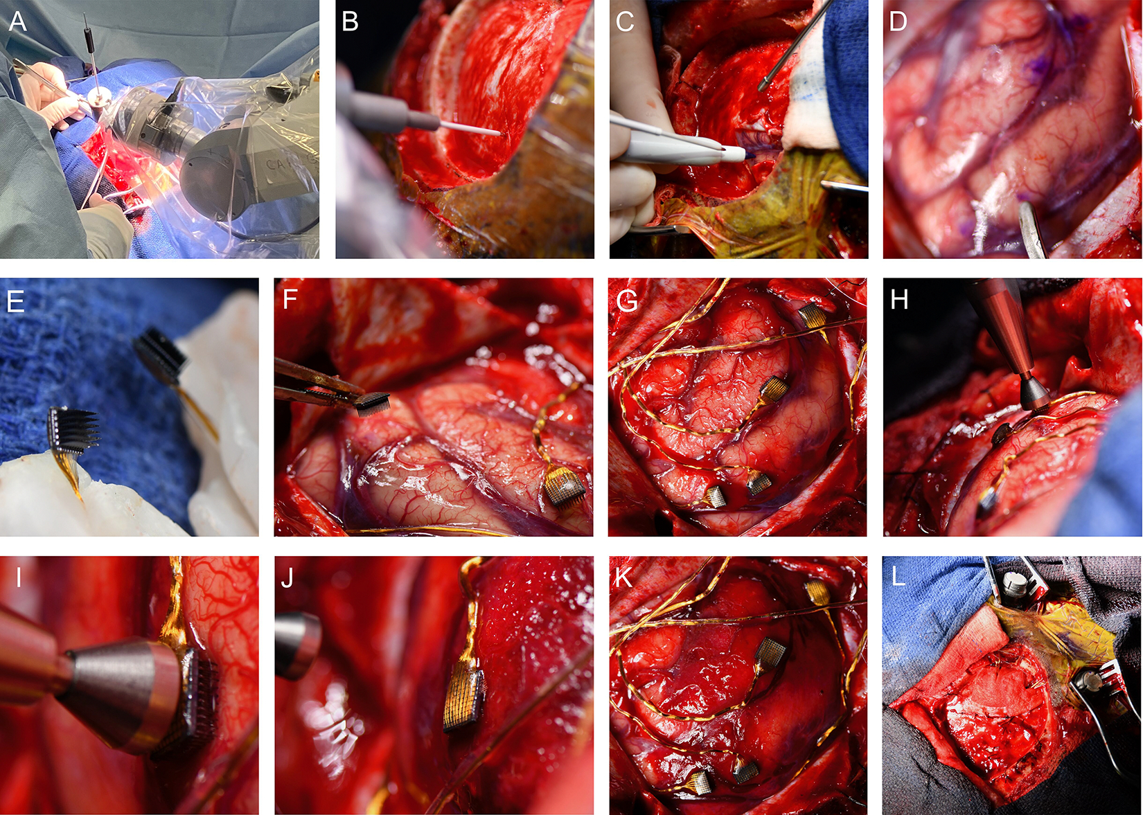
Operation work flow (microelectrode array insertion).
A: The robotic system indicating an insertion point on the dura matter (B: magnified view).
C: The dura matter was opened with a small incision, guided by the robotic system. Immediately after that, the insertion point was marked with a pen at the cerebral surface.
D: The four insertion points are marked and the dura matter is fully opened. The tip of a micro spatula indicates somatosensory area for the thumb.
E: The Utah Arrays are held by bone wax. Note that the electrodes are delicate and fragile, requiring careful handling.
F-G: The arrays are deployed to the planed points.
H: The pneumatic insertion device is positioned over the middle of the back of the array, perpendicular to the brain surface.
I: A magnified image of the pneumatic insertion device head before the impact. The microelectrode is slightly pressing on the brain surface but has not yet been inserted.
J: Microelectrodes are inserted by the pneumatic device that uses a high-speed plunger on the back of the array. See that the microelectrode shanks are embedded in the brain and not visible at this point.
K: All arrays inserted into the brain. Note that the position of arrays is the identical to the planned location (G).
L: A general view of the device installation after dural closure.
Video 1:
Confirmation of the microelectrodes array implantation using an endoscope.
Results
A fusion image of the preoperative T1W-MRI and postoperative CT verified that the devices were positioned as intended (Figure 4A–B). No acute hemorrhagic or the other types of complications were observed on the postoperative CT scan (Figure 4C). The participant developed a local and limited skin infection after surgery, which was treated with focal skin debridement and short-term antibiotics, resulting in complete resolution.
Figure 4:

Postoperative images and data.
A: A 3D brain surface image with microelectrodes arrays. The array was depicted as the object (red). The objects were depicted by localizing the micro electrodes arrays on the fusion images of postoperative CT and preoperative T1W-MRI (MPRAGE).
B: A magnified 3D image shows the location of each array (T: thumb sensory, I: index sensory, H: hand motor, S: shoulder motor areas) around the central sulcus (purple line). Note that the positions of the array depicted are consistent with the insertion points as intented (see Figure 3).
C: A postoperative CT (axial) shows device artifact without any surgical complications.
D: A 3D postoperative bone image showing the connectors of device (pedestals) and the craniotomy field where the arrays were implanted.
Postoperative experimental protocols were performed by the neural engineering team through the externalized pedestals (Figure 4D). At 14 days post-implant, the participant attempted 2D control of a virtual arm and hand using the motor cortex arrays for the first time and was successful on 20/20 attempts (Video 2). At 14 days and 6 months post-implant, multiple microstimulation surveys were conducted for each electrode of the somatosensory cortex arrays and elicited sensations in the little, ring, and middle fingers, and at the base of the index finger or thumb on the palm. At the time of this manuscript writing (~1 year post-implant), the devices remain functional and the clinical trial and associated experiments are ongoing. Figure 5 illustrates the recording quality from the motor arrays at 14, 100, and 200 days post-implant, and evoked sensations through intracortical microstimulations on the somatosensory cortex arrays.
Video 2:
Attempting brain-controlled movement of the virtual arm toward the target. The BCI was calibrated as in previous report14 to enable the participant to control 2 dimensional (2D) endpoint velocity of the hand using neural activity generated by the participant attempting to move the virtual arm. The 2D BCI enabled the participant to move the hand to any location in a vertical plane. For each trial, a transparent target appeared and when signaled by the audio cue, the participant attempted to reach towards the target within a predefined radius of success. After successfully acquired the target, the hand was paused by the computer, a new target appeared, and then an audio cue signaled the transition to brain control. This video shows the first brain-control attempted by the participant 2 weeks after implant.
Figure 5:

Neural signal stability.
A: Distribution of median peak-to-peak voltage amplitudes across all channels of the medial (targeting the shoulder motor area: orange) and lateral (hand motor area: blue) motor cortex arrays (left), and 50 representative waveforms from a channel with the median peak-to-peak voltage value (VPP) for each array (right) across 3 timepoints post-implantation, showing that high signal quality is maintained.
B: Array locations (MC: motor cortex array, SC: somatosensory cortex array) and illustrations of hand and magnified arrays colored based on the projected fields elicited by intracortical microstimulations (ICMS) for each electrode. The illustration shows the centroid of the projected field across all survey repetitions of each electrode. The lateral array mainly corresponds to the thumb to middle finger, while the medial array corresponds to the little finger. Further details regarding this result are discussed elsewhere (Downey et al., 2024).34
Discussion
We described the rationale and utility of robotics in BCI surgery and reported a case of robot-assisted BCI implantation where four intracortical microelectrodes arrays were implanted in the sensorimotor cortex of a man with tetraplegia due to C4 spinal cord injury. Specifically, the robotic stereotactic system was used to plan the array location and insertion trajectories, which then informed the crantiotomy location and enabled intraoperative confirmation of expected array placement. Preoperative plans and surgical flow were conceived based on our extensive experience and those were translated into the implementation of a safe, feasible and precise robot-assisted surgical approach.18,34 Consequently, all of arrays were successfully inserted and the signals from the implanted arrays demonstrate the expected motor activity suitable for BCI control and sensory responses suitable for restoration of touch. Robotic neurosurgery is well-suited for BCI and it will likely continue to expand in the near future. Future studies may incorporate surgical robots into the surgical procedures themselves, assisting with opening the craniotomy or inserting the arrays directly.
The approach utilized here is a precise targeting technique for the implantation plan of intracortical sensorimotor BCI, especially rigid microelectrodes arrays, such as the Utah Arrays. This technique can be applied to implantation targets beyond the sensorimotor cortex. For example, some studies have targeted the posterior parietal cortex, premotor cortex, or Broca’s area.21,38 From a comparative viewpoint of surgical technique, image-guided surgery has been the conventional standard approach for BCI implantation. This is simple and time-efficient, however, its accuracy is limited since aligning the marking with trajectory relies on targeting through human hands, using a hand-held pointer. Another approach is conventional stereotactic frame-based surgery. However, a considerable number of papers has indicated that the robotic surgery has higher time-efficiency and may have equivalent or higher accuracy comparing to classic stereotactic approach.18,31 The advantage of a frame-based approach using a rigid reference frame lies in the ability to simulate the trajectory on a phantom, improving accuracy and precision before the actual procedure. Furthermore, the robotic system accurately projected the array locations to the skin surface using the laser indicator, assisting in planning the skin incisions and craniotomy. Therefore, a robot-guided method, that has the advantage of repetitive, rapid and precise motion without human errors, substantially assists in overcoming the challenges inherent in the BCI implantation with a need for multiple accurate insertion point targetings.
In this case, we implanted four arrays and they were each inserted with a single impact of a pneumatic device. Since there are no avascular areas in the cerebral cortex, intracortical array insertion poses the unavoidable risks of the small vessel disruption and hemorrhage, which lead to neuronal loss and signal quality degradation.10 Moreover, each insertion causes mechanical disruption to the cortex that may initiate a foreign body response, which can result in signal instability.4 Hence, to avoid multiple re-insertion maneuvers that increase the chances for cortical damage, we visually aligned the array and pneumatic device perpendicular to the brain surface. In the future, to improve reliability and increase time efficiency, it would be desirable if the maneuver could be semi-automatically controlled by robotics. A real-time visual feedback via endoscopy that we demonstrated potentially contributes to such system in the device position control. In this respect, Neuralink’s light-based automatic real-time feed back approach is advanced.20 Furthermore, their almost fully robotic approach has promising time efficiency, yet its impact on safety and accuracy, as well as on the outcome of BCI itself, remains to be evaluated.39
A further challenge in this process lies in establishing a standard insertion method that is reliable and less reliant on human involvement for current state-of-the-art intracortical devices that underpin the bulk of the BCI works to date40,41, and to develop and improve surgical techniques that allow new technologies to be applied to interventional devices while advances in neuroscience and neuroengineering continues. This will likely include the involvement of neurosurgeons in the device development stage. Moreover, while robotic-guidance in surgical procedures is undisputed in accuracy, there remains the intraperative challenge of refining the insertion location to account for microvessels that were invisible during preoperative imaging. Therefore, the multi-dimentional approaches are required to further improve the methodology.
Limitation
We evaluated signal robustness over a relatively short follow-up period of ~1 year and in a single particiant, thus, a validation study with a larger number of participants with long-term follow-up is required. Despite the limitation, robotic surgery is a well-suited technique for BCI device implantation compared to conventional approach and is adaptable to future advances in this field.
Conclusions
Robot-assisted neurosurgery technique was successfully translated into BCI device implantation as part of an early feasibility trial with the long term goal of restoring upper limb function. The technique was demonstrated to be accurate and time-efficient, and subsequently contributed to high-quality signal communication.
Acknowledgments:
The authors are grateful to all the staff members at the University of Pittsburgh Medical Center and to the study participant for his extraordinary commitment to the study.
Footnotes
Conflict of Interest Statement:
Research reported in this publication was supported by the National Institute Of Neurological Disorders And Stroke of the National Institutes of Health under Award Numbers UH3NS107714, U01NS123125, and R01NS121079. The content is solely the responsibility of the authors and does not necessarily represent the official views of the National Institutes of Health. JGM is a consultant for Zimmer-Biomet. NH and RG served as consultants for Blackrock Neurotech, Inc, at the time of the study. RG is also on the scientific advisory board of Neurowired LLC. MB, JC, and RG received research funding from Blackrock Neurotech, Inc. though that funding did not support the work presented here. Other authors have no personal financial or institutional interest in any of the drugs, materials, or devices described in this article. We confirm that we have read the Journal’s position on issues involved in ethical publication and affirm that this report is consistent with those guidelines.
Previous Presentations: None
References
- 1.WHO. Spinal cord injury. November 19, 2013. (Accessed January 7, 2024); https://www.who.int/news-room/fact-sheets/detail/spinal-cord-injury
- 2.National Spinal Cord Injury Statistical Center (NSCISC). 2022 Annual Statistical Report. 2022. (Accessed March 8, 2024); https://www.nscisc.uab.edu
- 3.Collinger JL, Gaunt RA, Schwartz AB. Progress towards restoring upper limb movement and sensation through intracortical brain-computer interfaces. Current Opinion in Biomedical Engineering. 2018/12/01/ 2018;8:84–92. doi: 10.1016/j.cobme.2018.11.005 [DOI] [Google Scholar]
- 4.Kozai TD, Jaquins-Gerstl AS, Vazquez AL, Michael AC, Cui XT. Brain tissue responses to neural implants impact signal sensitivity and intervention strategies. ACS Chem Neurosci. Jan 21 2015;6(1):48–67. doi: 10.1021/cn500256e [DOI] [PMC free article] [PubMed] [Google Scholar]
- 5.Losanno E, Mender M, Chestek C, Shokur S, Micera S. Neurotechnologies to restore hand functions. Nature Reviews Bioengineering. 2023/06/01 2023;1(6):390–407. doi: 10.1038/s44222-023-00054-4 [DOI] [Google Scholar]
- 6.Pandarinath C, Bensmaia SJ. The science and engineering behind sensitized brain-controlled bionic hands. Physiol Rev. Apr 1 2022;102(2):551–604. doi: 10.1152/physrev.00034.2020 [DOI] [PMC free article] [PubMed] [Google Scholar]
- 7.Sponheim C, Papadourakis V, Collinger JL, et al. Longevity and reliability of chronic unit recordings using the Utah, intracortical multi-electrode arrays. J Neural Eng. Dec 28 2021;18(6)doi: 10.1088/1741-2552/ac3eaf [DOI] [PMC free article] [PubMed] [Google Scholar]
- 8.Kozai TD, Marzullo TC, Hooi F, et al. Reduction of neurovascular damage resulting from microelectrode insertion into the cerebral cortex using in vivo two-photon mapping. J Neural Eng. Aug 2010;7(4):046011. doi: 10.1088/1741-2560/7/4/046011 [DOI] [PMC free article] [PubMed] [Google Scholar]
- 9.Polikov VS, Tresco PA, Reichert WM. Response of brain tissue to chronically implanted neural electrodes. J Neurosci Methods. Oct 15 2005;148(1):1–18. doi: 10.1016/j.jneumeth.2005.08.015 [DOI] [PubMed] [Google Scholar]
- 10.Szymanski LJ, Kellis S, Liu CY, et al. Neuropathological effects of chronically implanted, intracortical microelectrodes in a tetraplegic patient. J Neural Eng. Jul 27 2021;18(4)doi: 10.1088/1741-2552/ac127e [DOI] [PubMed] [Google Scholar]
- 11.Salatino JW, Ludwig KA, Kozai TDY, Purcell EK. Glial responses to implanted electrodes in the brain. Nat Biomed Eng. Nov 2017;1(11):862–877. doi: 10.1038/s41551-017-0154-1 [DOI] [PMC free article] [PubMed] [Google Scholar]
- 12.Ajiboye AB, Willett FR, Young DR, et al. Restoration of reaching and grasping movements through brain-controlled muscle stimulation in a person with tetraplegia: a proof-of-concept demonstration. Lancet. May 6 2017;389(10081):1821–1830. doi: 10.1016/s0140-6736(17)30601-3 [DOI] [PMC free article] [PubMed] [Google Scholar]
- 13.Bouton CE, Shaikhouni A, Annetta NV, et al. Restoring cortical control of functional movement in a human with quadriplegia. Nature. May 12 2016;533(7602):247–50. doi: 10.1038/nature17435 [DOI] [PubMed] [Google Scholar]
- 14.Collinger JL, Wodlinger B, Downey JE, et al. High-performance neuroprosthetic control by an individual with tetraplegia. Lancet. Feb 16 2013;381(9866):557–64. doi: 10.1016/s0140-6736(12)61816-9 [DOI] [PMC free article] [PubMed] [Google Scholar]
- 15.Hochberg LR, Bacher D, Jarosiewicz B, et al. Reach and grasp by people with tetraplegia using a neurally controlled robotic arm. Nature. May 16 2012;485(7398):372–5. doi: 10.1038/nature11076 [DOI] [PMC free article] [PubMed] [Google Scholar]
- 16.Flesher SN, Collinger JL, Foldes ST, et al. Intracortical microstimulation of human somatosensory cortex. Sci Transl Med. Oct 19 2016;8(361):361ra141. doi: 10.1126/scitranslmed.aaf8083 [DOI] [PubMed] [Google Scholar]
- 17.Flesher SN, Downey JE, Weiss JM, et al. A brain-computer interface that evokes tactile sensations improves robotic arm control. Science. May 21 2021;372(6544):831–836. doi: 10.1126/science.abd0380 [DOI] [PMC free article] [PubMed] [Google Scholar]
- 18.Abou-Al-Shaar H, Mallela AN, Corson D, Sweat J, González Martínez JA. Robotics in Epilepsy Surgery. In: González Martínez JA, Cardinale F, eds. Robotics in Neurosurgery: Principles and Practice. Springer International Publishing; 2022:105–117. [Google Scholar]
- 19.Ball T, González-Martínez J, Zemmar A, et al. Robotic Applications in Cranial Neurosurgery: Current and Future. Oper Neurosurg (Hagerstown). Nov 15 2021;21(6):371–379. doi: 10.1093/ons/opab217 [DOI] [PubMed] [Google Scholar]
- 20.Musk E An Integrated Brain-Machine Interface Platform With Thousands of Channels. J Med Internet Res. 2019/10/31 2019;21(10):e16194. doi: 10.2196/16194 [DOI] [PMC free article] [PubMed] [Google Scholar]
- 21.Aflalo T, Kellis S, Klaes C, et al. Neurophysiology. Decoding motor imagery from the posterior parietal cortex of a tetraplegic human. Science. May 22 2015;348(6237):906–10. doi: 10.1126/science.aaa5417 [DOI] [PMC free article] [PubMed] [Google Scholar]
- 22.Armenta Salas M, Bashford L, Kellis S, et al. Proprioceptive and cutaneous sensations in humans elicited by intracortical microstimulation. Elife. Apr 10 2018;7doi: 10.7554/eLife.32904 [DOI] [PMC free article] [PubMed] [Google Scholar]
- 23.Brandman DM, Hosman T, Saab J, et al. Rapid calibration of an intracortical brain-computer interface for people with tetraplegia. J Neural Eng. Apr 2018;15(2):026007. doi: 10.1088/1741-2552/aa9ee7 [DOI] [PMC free article] [PubMed] [Google Scholar]
- 24.Eichenlaub JB, Jarosiewicz B, Saab J, et al. Replay of Learned Neural Firing Sequences during Rest in Human Motor Cortex. Cell Rep. May 5 2020;31(5):107581. doi: 10.1016/j.celrep.2020.107581 [DOI] [PMC free article] [PubMed] [Google Scholar]
- 25.Gilja V, Pandarinath C, Blabe CH, et al. Clinical translation of a high-performance neural prosthesis. Nat Med. Oct 2015;21(10):1142–5. doi: 10.1038/nm.3953 [DOI] [PMC free article] [PubMed] [Google Scholar]
- 26.Guan C, Aflalo T, Zhang CY, et al. Stability of motor representations after paralysis. Elife. Sep 20 2022;11doi: 10.7554/eLife.74478 [DOI] [PMC free article] [PubMed] [Google Scholar]
- 27.Hochberg LR, Serruya MD, Friehs GM, et al. Neuronal ensemble control of prosthetic devices by a human with tetraplegia. Nature. Jul 13 2006;442(7099):164–71. doi: 10.1038/nature04970 [DOI] [PubMed] [Google Scholar]
- 28.Kim SP, Simeral JD, Hochberg LR, Donoghue JP, Black MJ. Neural control of computer cursor velocity by decoding motor cortical spiking activity in humans with tetraplegia. J Neural Eng. Dec 2008;5(4):455–76. doi: 10.1088/1741-2560/5/4/010 [DOI] [PMC free article] [PubMed] [Google Scholar]
- 29.Simeral JD, Kim SP, Black MJ, Donoghue JP, Hochberg LR. Neural control of cursor trajectory and click by a human with tetraplegia 1000 days after implant of an intracortical microelectrode array. J Neural Eng. Apr 2011;8(2):025027. doi: 10.1088/1741-2560/8/2/025027 [DOI] [PMC free article] [PubMed] [Google Scholar]
- 30.Rousche PJ, Normann RA. Chronic recording capability of the Utah Intracortical Electrode Array in cat sensory cortex. J Neurosci Methods. Jul 1 1998;82(1):1–15. doi: 10.1016/s0165-0270(98)00031-4 [DOI] [PubMed] [Google Scholar]
- 31.González-Martínez J, Bulacio J, Thompson S, et al. Technique, Results, and Complications Related to Robot-Assisted Stereoelectroencephalography. Neurosurgery. Feb 2016;78(2):169–80. doi: 10.1227/neu.0000000000001034 [DOI] [PubMed] [Google Scholar]
- 32.Mallela AN, Beiriger J, Gersey ZC, et al. Targeting the Future: Developing a Training Curriculum for Robotic Assisted Neurosurgery. World Neurosurg. Nov 2022;167:e770–e777. doi: 10.1016/j.wneu.2022.08.076 [DOI] [PubMed] [Google Scholar]
- 33.Collinger JL, Kryger MA, Barbara R, et al. Collaborative approach in the development of high-performance brain-computer interfaces for a neuroprosthetic arm: translation from animal models to human control. Clin Transl Sci. Feb 2014;7(1):52–9. doi: 10.1111/cts.12086 [DOI] [PMC free article] [PubMed] [Google Scholar]
- 34.Downey JE, Schone HR, Foldes ST, et al. A roadmap for implanting microelectrode arrays to evoke tactile sensations through intracortical microstimulation. medRxiv. 2024:2024.04.26.24306239. doi: 10.1101/2024.04.26.24306239 [DOI] [PMC free article] [PubMed] [Google Scholar]
- 35.McGovern RA, Knight EP, Gupta A, et al. Robot-assisted stereoelectroencephalography in children. J Neurosurg Pediatr. Dec 7 2018;23(3):288–296. doi: 10.3171/2018.7.Peds18305 [DOI] [PubMed] [Google Scholar]
- 36.Waziri A, Schevon CA, Cappell J, Emerson RG, McKhann GM 2nd, Goodman RR. Initial surgical experience with a dense cortical microarray in epileptic patients undergoing craniotomy for subdural electrode implantation. Neurosurgery. Mar 2009;64(3):540–5; discussion 545. doi: 10.1227/01.Neu.0000337575.63861.10 [DOI] [PMC free article] [PubMed] [Google Scholar]
- 37.Rousche PJ, Normann RA. A method for pneumatically inserting an array of penetrating electrodes into cortical tissue. Ann Biomed Eng. 1992;20(4):413–22. doi: 10.1007/bf02368133 [DOI] [PubMed] [Google Scholar]
- 38.Willett FR, Kunz EM, Fan C, et al. A high-performance speech neuroprosthesis. Nature. Aug 2023;620(7976):1031–1036. doi: 10.1038/s41586-023-06377-x [DOI] [PMC free article] [PubMed] [Google Scholar]
- 39.Drew L Neuralink brain chip: advance sparks safety and secrecy concerns. Nature. Mar 2024;627(8002):19. doi: 10.1038/d41586-024-00550-6 [DOI] [PubMed] [Google Scholar]
- 40.Maynard EM, Nordhausen CT, Normann RA. The Utah intracortical Electrode Array: a recording structure for potential brain-computer interfaces. Electroencephalogr Clin Neurophysiol. Mar 1997;102(3):228–39. doi: 10.1016/s0013-4694(96)95176-0 [DOI] [PubMed] [Google Scholar]
- 41.Sahasrabuddhe K, Khan AA, Singh AP, et al. The Argo: a high channel count recording system for neural recording in vivo. J Neural Eng. Feb 24 2021;18(1):015002. doi: 10.1088/1741-2552/abd0ce [DOI] [PMC free article] [PubMed] [Google Scholar]