

Abstract
Unmanned aerial vehicles (UAVs) used as aerial base stations (ABS) can provide economical, on-demand wireless access. This research investigates dynamic resource allocation in multi-UAV-enabled communication systems with the aim of maximizing long-term rewards. More specifically, without exchanging information with other UAVs, every UAV chooses its communicating users, power levels, and sub-channels to establish communication with a ground user. In the proposed work, the dynamic scheme-based resource allocation is investigated of communication networks made possible by many UAVs to achieve the highest possible performance level over time. Specifically, each UAV selects its connected users, battery power, and communication channel independently, without exchanging information across multiple UAVs. This allows each UAV to connect with ground users. To model the unpredictability of the environment, we present the problem of long-term allocation of system resources as a stochastic game to maximize the anticipated reward. Each UAV in this game plays the role of a learnable agent, and the system solution for resource allocation matches the actions made by the UAV. Afterward, we built a framework called reward-based multi-agent learning (RMAL), in which each agent uses learning to identify its best strategies based on local observations. RMAL is an acronym for ″reward-based multi-agent learning″. We specifically offer an agent-independent strategy where each agent decides algorithms separately but cooperates on a common Q-learning-based framework. The performance of the suggested RMAL-based resource allocation method may be enhanced by employing the right development and exploration parameters, according to the simulation findings. Secondly, the proposed RMAL algorithm provides acceptable performance over full information exchange between UAVs. Doing so achieves a satisfactory compromise between the increase in performance and the additional burden of information transmission.
Keywords: Unmanned aerial vehicles, Aerial base stations, Dynamic resource allocation, Multi-Agent learning, Decentralized Decision-Making
Subject terms: Electrical and electronic engineering, Mechanical engineering
Introduction
Recently, there has been a rise in interest in airborne communication networks, which encourages the development of novel wireless infrastructure deployment techniques1. Aerial communication systems may provide better system capacity and coverage, which is why this occurred. Unmanned aerial vehicles (UAVs), also known as remotely piloted aircraft systems (RPAS) or drones, are small unmanned aircraft that may be deployed fast2. These are yet another kind of Third Generation Partnership Project-built LTE-A (long-term evolution - advanced) system (3GPP). In contrast to ground communication, the channel characteristics for communication between UAV and the ground are more likely to be line-of-sight (LoS) links2, which makes wireless communication easier. With regard to deployment, navigation, and control, UAVs built on a variety of airborne platforms have drawn a significant amount of academic and industry effort3. To increase UAV communication systems’ coverage and energy efficiency, resource allocation which includes transmit power, service users, and sub-channel is also required4. This is because crucial communication issues are involved. UAVs can typically be deployed in less time than terrestrial base stations and offer greater configuration flexibility5. The distance between various UAV deployments and the altitude of UAV-enabled small base stations are studied by the author4. A cyclic packing-based three-dimensional (3D) deployment algorithm is developed in reference6 to maximize the performance of the downlink coverage. Additionally develops a 3D deployment method for a single UAV to maximize the number of coverage users6. Additionally, proposes a continuous UAV placement method by maintaining the same altitude7. This plan intends to reduce the overall number of UAVs needed while making sure that each genuine ground user is protected by at least one UAV8. Even though the UAV deployment has been optimized, the design of UAV trajectories to optimize communication performance has received considerable attention, as evidenced by9–11. The authors investigate the problem of throughput maximization and view UAVs as mobile relays9. To achieve optimal results, they optimize the power distribution and UAV trajectory. Then, in reference9, successive convex approximation (SCA) is proposed as a method for the design of UAV trajectories. The authors of9 examine the UAV trajectory design that reduces the amount of time needed to finish a task using UAV multicast systems. To accomplish this, they changed an uninterrupted trajectory into a set of distinct way-points. Furthermore10, consider wireless communication systems capable of supporting multiple UAV systems. This paper analyses a collaborative design for the best trajectory and resource distribution by increasing the minimum throughput for all users to maintain fairness. To mitigate the delay of the sensing task while maintaining the overall rate of a multi-UAV aided uplink single-cell network, the authors of12 suggest a joint sub-channel allocation and trajectory design technique. This can be accomplished by designing a trajectory that takes both the total rate and latency of the sensing task into account. Due to their adaptability and maneuverability, the control design of UAVs is constrained by the need for human intervention. The performance of UAV communication systems necessitates intelligent UAV control based on machine learning as a result13. The design of neural network-based trajectories for UAVs is examined from the standpoint of manufacturing architecture in14,15. The paper16 proposes a weighted expectation-based UAV on-demand predictive deployment method to minimize transmit power in UAV-enabled communication systems. This method uses a Gaussian mixture model to construct the data distribution.
In the related work16, the authors investigate autonomous path planning for UAVs by jointly considering energy efficiency, transmission delay, and interference management. To address this complex optimization problem, they propose a deep reinforcement learning framework based on Echo State Networks (ESNs), enabling adaptive decision-making in dynamic environments. Furthermore, the same study presents a resource allocation strategy leveraging Liquid State Machines (LSMs) for efficient spectrum utilization across both licensed and unlicensed LTE bands in cache-enabled UAV networks. In a related work17, a joint channel and time-slot selection mechanism for multi-UAV systems is introduced. The proposed approach employs log-linear learning to optimize spectrum sharing and mitigate collisions in a distributed manner, thereby enhancing the overall communication performance of UAV-enabled networks17.
Machine and deep learning are two types of artificial intelligence model that learns directly from the data with explicitly programming a computer system to detect and recognition, both are promising and potent tools that can provide autonomous and effective solutions to intelligently improve communication systems that support UAVs18. However, the majority of research contributions have been on how UAVs are deployed and how their trajectories are designed in communication systems16. Prior research has primarily focused on time-independent scenarios, despite11,12 discussing resource allocation schemes for UAV-supported communication systems, including transmit power and sub-channels. In other words, the optimal design is independent of the time being taken into account. Additionally19,20, investigated the possibility of resource allocation techniques based on machine learning for time-dependent scenarios. However, the majority of proposed machine learning algorithms focus on scenarios involving a single UAV or multiple UAVs, assuming that each UAV possesses comprehensive network information. Due to the rapid movement of UAVs21,22, it is not simple to acquire a comprehensive understanding of the dynamic environment in practice. This creates a difficult environment for the design of reliable UAV wireless communication, which poses a significant challenge. Additionally, the majority of earlier research contributions were on centralized techniques, making modeling and computing tasks challenging as the network’s scale continues to grow. For communication systems that allow UAVs, reward-based multi-agent learning (RMAL) can offer a distributed view of intelligent resource management. This is especially useful in situations where each UAV only has access to its local data23.
In dynamic UAV-enabled communication networks, centralized control or full network state awareness is often impractical due to high mobility, limited energy, and real-time operational constraints. Most existing solutions either assume complete inter-UAV information sharing or rely on static deployment strategies. In contrast, the proposed RMAL (Reward-Based Multi-Agent Learning) framework enables each UAV to make decentralized resource allocation decisions using only local observations, eliminating the need for inter-agent communication. This reduces overhead while retaining adaptability in highly dynamic environments. The motivation for using RMAL lies in its ability to capture environmental uncertainty through a stochastic game formulation, enabling each UAV to maximize long-term rewards independently via Q-learning. This makes the method scalable, practical, and well-suited for real-time UAV applications24.
Based on the proposed framework, the following summarizes our primary contributions:
To enhance multi-UAV downlink systems’ long-term effectiveness, our work focuses on concurrently constructing user, power level, and sub-channel selection algorithms. To ensure reliable communication, we specifically created a limited energy efficiency function based on the quality-of-services (QoS) as a reward mechanism. The exceptional nature of the formulation of the optimization problem can be attributed to its time-dependent and uncertain nature. To tackle this challenging issue, we describe a method for dynamic resource allocation based on reward learning.
Our method of analyzing the dynamic resource allocation problem of a multi-UAV system is based on a novel stochastic game theory. According to this design, every UAV performs the role of a learning agent, and every resource allocation strategy is based on the actions of the UAV. This gives us the ability to describe the dynamic resource allocation issue in a system of several UAVs. Each UAV’s actions in a designed random game specifically satisfy the properties of the Markov chain. This suggests that a UAV’s rewards depend only on its current state and actions. Additionally, resource allocation problems for various multi-UAV dynamic systems may be simulated using the framework.
We created an RMAL-based resource allocation algorithm to solve stochastic formula games that take place in multi-UAV systems. Since each UAV uses the traditional Q-learning techniques and functions as its learning agent, the behaviors of the UAVs are not taken into consideration. We created a resource allocation system based on the RMAL algorithm to tackle stochastic formula games that happen in multi-UAV systems. Each UAV functions as its learning agent, carrying out common Q-learning algorithms without taking into account what other UAVs are doing. This significantly reduces the amount of data shared between UAVs and the computational work performed by each UAV. In addition, we provide evidence that the RMAL-based algorithm for resource allocation converges.
Various system parameters are used to derive the development and exploration parameters of the
 -greedy algorithm from the simulation results presented here. In addition, simulation results demonstrate that the RMAL-based multi-UAVs system resource allocation framework provides a satisfactory trade-off between performance increases and increases in the quantity of information that must be exchanged.
To facilitate clarity and improve comprehension of technical terms used throughout this study, a comprehensive list of abbreviations is presented in Table 1. This table provides definitions for commonly used acronyms related to UAV-enabled communication systems, reinforcement learning, and wireless network modeling. The summarized notations serve as a reference for readers to interpret various terminologies consistently within the context of this work.
Table 1.
Summary of acronyms.
| Acronyms | Definition | Acronyms | Definition |
|---|---|---|---|
| UAV | Unmanned Aerial Vehicle | NLoS | None-Line-of-Sight |
| AGU | Authorized Ground Users | SINR | Signal to Interference Plus Noise Ratio |
| A2G | Air to Ground | MDS | Markov Decision Scheme |
| LoS | Line-of-Sight | UAS | Unmanned Aerial System |
| 3D | 3 Dimensions | QoS | Quality of Service |
| RMAL | Reward-Based Multi-Agent Learning | 5G | Fifth Generation |
| LTE | Long Term Evolution | CSI | Channel State Information |
System model
We presented a multi-UAVs A2G communication system, depicted in Fig. 1, that operates on a discrete timeline and is comprised of a single antenna UAVs X and U are the users of a single antenna, represented by  and
and  respectively. Randomly dispersed the ground users on a radius
  Disks. As depicted in Fig. 1, several UAVs fly over the area and interact directly with the ground users25 via an aerial communication link. The UAV total bandwidth
  is subdivided into orthogonal sub-channels K, abbreviated as
  In addition, the UAV is expected to operate autonomously based on a preprogrammed flight plan without human interaction, as described in20. In other words, a preprogrammed flight plan predetermined the UAV’s trajectory. Figure 1 shows three UAVs flying over the region of interest along a predetermined path. This article examines the resource distribution dynamic design in UAV systems concerning the user, power level, and sub-channel selection. In addition, it is believed that the communication among UAVs is without a central controller, and the a lack of global understanding in the wireless communication environment27. In simple words, local knowledge exists regarding the UAV and the user’s CSI. In practice, this assumption is reasonable due to UAV mobility, similar to research contributions21,22.
Fig. 1.

The proposed system for UAV-enabled communication employs Reinforcement Learning for decentralized dynamic resource allocation.
A2G channel model
Compared to terrestrial communication propagation, A2G channels are significantly reliant on altitude, elevation angle, and propagation environment. In reference3,21, we investigated the dynamic resource allocation topic in multi-UAVs under A2G channel model:
The Probabilistic Models: As demonstrated in21,29, The probabilistic rout loss model, which allows for the independent treatment of line-of-sight (LoS) and non-line-of-sight (NLoS) links with different probabilities, can be used to simulate the A2G communication link. According to29, the likelihood of establishing a LoS connection between time slot D,
 , and
, and  is the ground user given by environment-dependent constants a and b.
 |
1 |
 denotes
  and user
  and the altitude of
  denoted by H. In addition,
 is the NLoS link probability.
The corresponding Non-Line-of-Sight (NLoS) probability is:
 |
2 |
The trajectory path-loss LoS and NLoS from the permitted ground user U in time slot D to the  may be expressed as follows,
 |
3 |
 |
4 |
where  denotes the route loss in free space with
  and the carrier frequency
  . Additionally,
  and
and  representing the average additional path-losses LoS and NLoS, respectively. Consequently, the following representation may be used to show the average trajectory path loss between
  and user
  during time slot D:
 |
5 |
The LoS Model: In reference8, for practical A2G communication, the LoS model provides a good approximation. The path loss between an authorized ground user and a UAV depends on both their locations and the kind of propagation, according to the LoS model30. The channel gains between the authorized users on the ground and the UAVs are computed, taking into account their relative distances, using the LoS model and the free path loss model. The power gain of the LoS channel model in time slot D from the X-th UAV to the approved ground users U-th can be represented as follows:
 |
6 |
where 
 indicate the horizontal position of the
  in time slot D. Consequently,
  reflects the user’s location
  . In addition,
  is denoted by the channel power with the distance
  whereas
  is the path loss index.
The signal model
Each pair of UAVs operating on the same sub-channel causes interference for ground users when it comes to UAV-to-ground communication. Let  be a sub-channel indication, where
  if
if  occupies sub-channel
  during time slot D; otherwise,
  . It is satisfactory
 |
7 |
.
In other words, each drone is restricted to a single sub-channel per time. Make  A user-facing indication.
  if the user
  in the time frame D provided by the
  ;
;  if not. Thus, at time slot D, on sub-channel
  and the SNIR of the UAV to ground transmission between
  and authorized user U are the following:
 |
8 |
where  indicates the channel gain of
  and the authentic user U in sub-channel
  and the time slot D.
  indicates the transmit power chosen by
  for time slot D. The
  with
with  . The SINR of the
  can be stated as follows for any time slot D:
 |
9 |
In22, the UAVs implement discrete transmit power control to manage interference and optimize communication performance within the network. The vector  shows the transmit power value for each UAV that is in communication with the relevant associated user. For each
  , the binary variable
  is defined.
  if
if  decides to transmit at time slot D with power level
  ; else
  . Note that for each D time slot,
  may only choose single power.
 |
10 |
Now, the  has a limited set of power-level selection options including the following:
 |
11 |
Similar to user selection via  , all sub-channel selection has finite sets that are as follows:
 |
12 |
 |
13 |
Furthermore, we also assume that the multi-UAV system runs on a discrete-time basis, with the time timeline being divided into equal, non-overlapping time intervals. In addition, it is expected that the communication parameters do not change between time slots. For the time slot index, let D be the integer value. Specially, when each UAV records the CSI and decisions of authorized ground users in time slots  at preset intervals, which is referred to as the decision cycle. We look into the following approach for scheduling UAV transmissions: each UAV receives a time slot D to begin transmission, and the handover must be completed after its decision cycle, in the time slot
  . We suppose that UAVs are unaware of the precise amount of time they spend in the network. This characteristic prompted us to develop an online learning system for the maximization of energy efficiency performance for the multi-UAV networks over the long run31.
The framework of stochastic game for multi-UAVs systems
In this part, it’s started with a description of the optimization challenges addressed in this study. To imitate the randomness of the environment, a random set is then used to formulate the joint power level, user, and sub-channel selection problem.
Problem formulation
Note that beginning with (6), each UAV transmits at full power for maximum throughput, resulting in greater interference with other UAVs32. To ensure reliable communication from the UAV, the primary objective of the dynamic design of power level, user, and sub-channel selection is to ensure that the SINR generated by the UAV does not fall below the predetermined threshold33. In particular, the mathematical form can be shown as follows:
 |
14 |
where  is the QoS threshold objective for UAV users. If constraint (14) is satisfied in time slot D, the UAV is awarded
  , which is characterized as the gap between throughput and power cost reached by the user, power level, and the selected sub-channel, otherwise it will earn no reward. Thus, the
  can be used to represent the reward function of the
  in D time slot:
 |
15 |
For every  , the instantaneous payoff is represented by
  . The power level in terms of cost per unit is
  . The instantaneous reward for
  in any D time slot relies on the following:
Unobserved data: sub-channel and power levels as well as channel gain selected by other UAVs. Note that we exclude the UAV’s fixed energy consumption, such as that of the control unit and data processing23.
Information observed: For the single user, power level and sub-channel decisions for
 , i.e.,
  . Additionally, it is dependent on the current channel gain
  ;
;
To maximize the long-term benefit, select the service users, power level transmission, and sub-channels for each time slot34. Specifically, we use future discounts24 as a criterion for evaluating each UAV. Specifically, at some point in the procedure, the discount reward equals the sum of its current period benefits plus the future reward discounted through a constant factor. Consequently, the following equation provides the long-term rewards for the  :
:
 |
16 |
where  represents
  1 discount factor. For example, if the value
  is near 0, the choice emphasizes short-term gain; but, if the
  is close to 1, visionary decisions are made. This value illustrates how future rewards influence optimum judgments.
In Eq. (16), the parameter τ represents the time-step offset or prediction horizon into the future, used to compute the discounted cumulative reward from the current time slot D onward. It starts at τ = 0 and increases indefinitely (theoretically up to +∞), reflecting the forward-looking nature of reinforcement learning where agents aim to optimize not only immediate but also long-term outcomes. Mathematically, τ indexes the number of steps into the future from the current decision point. The term Δ^τ serves as the discount factor that reduces the impact of future rewards as τ increases, making the algorithm more focused on near-term performance when Δ is small, and more long-term focused when Δ approaches 1. In practice, although the sum in (14) is over an infinite horizon, the influence of distant rewards becomes negligible for Δ < 1 and large τ, thus convergence is ensured. The cumulative reward function vₓ(D) is central to evaluating the utility of a UAV’s current policy, driving updates in Q-learning.
Next, we list the power level, sub-channel, and all the possible authorized users’ decisions taken by  ,
,  which may be written as
  and
and  is for the Cartesian product. Thus, the goal of each
  is to take decisions
  for the long-term performance maximization (14). For the UAV optimization problem,
  ,
,  can therefore be stated as follows:
 |
17 |
So, the optimum design of the multi-UAVs system under consideration comprises sub-problems X corresponding to various X UAVs. Additionally, since each UAV lacks knowledge about the other UAVs, such as their rewards, the problem cannot be precisely resolved (17).
In the subsections that follow, we make an effort to articulate joint sub-channel, power level, and the authorized user’s selection problems as non-cooperative stochastic games to resolve the random environment optimization problem (17).
Equation (15) formulates the optimization problem for each UAV as a single-agent objective, aiming to select a combination of user, sub-channel, and power level Ωₓ*(D) ∈ Φₓ that maximizes its instantaneous reward Srₓ(D). However, in a multi-UAV environment, each UAV’s reward is influenced not only by its own action but also by the simultaneous actions of other UAVs due to interference and shared sub-channels. Therefore, the independent optimization of Eq. (15) becomes coupled and interdependent, necessitating a game-theoretic formulation. To capture this interdependence, we reformulate the problem as a stochastic game (Markov game) where each UAV is a rational agent44. The global system state evolves over time, and each UAV selects its strategy based on its observed state. The key to solving this game lies in identifying a Nash equilibrium: a set of strategies µ* = [µ₁*, µ₂*, …, µₓ*] where no UAV can improve its expected cumulative reward by unilaterally deviating from its strategy, given the strategies of others.
Formulation of stochastic game
We modeled the problem in formula (17) in this section using the framework of a randomized game (also known as a Markov game)25 because it generalizes the Markov decision-making process to the case of multiple agents.
In the network under consideration, the UAV X communicates with the user without knowledge of the operating system. We assume that all UAVs are rational and self-catered. Thus, for the maximization of long-term returns (17), all UAVs select the movements independently at any given time slot D. So, the action of each  is chosen in its action space
 . The triples
  represent the actions performed by
  in time slot D, where
  stated the power level, user selection, and sub-channel of
  in time slot D, respectively. For each
  ,
,  represents the operation performed in time slot D by the other UAVs
  , which is
  .
.
As a result, the instantaneous SINR of  in time slot D can be expressed as follows:
 |
18 |
where 
 and
and  in (18). Additionally,
  represents the instantaneous channel matrix responses between
  and authorized ground user U at the given time slot D are the following:
 |
19 |
with 

 for all
  and
and  .
.
Each  can express its current SINR level
  at any given time slot D. Consequently, the
  state for each
  ,
,  is fully observed are the following:
 |
20 |
Let the state vector for all UAVs be  . As UAVs cannot cooperate, the
  in this article is unaware of the states of the other UAVs.
We assume that each UAV’s actions follow the rules of the Markov chain, which means that a UAV’s reward is solely dependent on its state and path of action at any given moment. According to26, the dynamics of the state in a stochastic game where each player only acts in each state are represented by the Markov chain38. The Markov chain is defined formally in the manner that is detailed below.
Definition 1
A discrete stochastic process called a finite state Markov chain has the following definition: Let’s assume that a q  q transition matrix E has entries
  and
and  for any 1
 q and that the collection of states
  is finite.
It progresses steadily from one state to the next. Assume that the chain is currently in the state.  . The next state’s
  probability is
 |
21 |
It is also known as the Markov property because it just depends on the current state and not any past states.
Consequently, the  reward function,
  , can be expressed as
 |
22 |
For the sake of compact notation, the time slot index D is expressed in superscript here. This notation will also be used for notational simplicity in the next sections.In (22), the action  determines the instantaneous transmit power, while the UAV’s instantaneous rate is given by
 |
23 |
The present state  , which is completely observed, and the actions that are partially observed (
 , which are both dependent on the current state
  , determine the pay-out
  that
that  will get at each time slot D, starting from (22). The chosen actions (
 and the previous state
  are the only factors used to determine the possibilities of the new random state
  to which
  flies. This happens at the next time slot D + 1. This process is repeated until all available slots have been filled.
  may specifically monitor its state
  and the related action
  at any time slot D, but it is unaware of other players’ actions,
  , and the precise values
  . Each player
  is also unaware of the probabilities of state transition. The examined UAV system in reference27 can thus be expressed as a stochastic game.
Definition 2
A tuple with values  can be used to construct a stochastic game where,
 denotes the state set with
  ;
;The group for players is
 ;
; stands for the player’s
  action set, while
  is the joint action set;
 is the probability function for sate transition, and it is affected by what each player does.
Specifically,  indicates the probability that the current state
  will change to the next stage
  by carrying out the joint action
  with
with  .
.
• For player  , where
  is a legitimately valuable reward function.
A mixed strategy in a stochastic game,  refers to a group of probability distributions over the potential actions, indicating the relationship between the action set and the state set. In further detail, the mixed strategy for
  in state
  is defined as:
  = [
= [ ], where each element
  of
of  shows the probability distribution of
  selecting a state action
  in state
  . X players and a vector of policies, one plan for each player, is called a joint strategy and has the form
  . Let
. Let  represents the same policy profile, but without player
  policy
  . Based on the aforementioned factors, each player
  in the specified stochastic game has the optimization goal of maximizing its expected payoff over time. The goal in (14) may be restated as follows for player
  under a joint strategy
  = [
= [ ] with assigning a strategy
  to each
  is
is
 |
24 |
Where  is the instantaneous reward received by
  at time
  and
and  stand for expectation operations. Individuals (UAVs) in the defined stochastic game have individual anticipated rewards that depend on the combined strategy rather than the players’ tactics. Because not all participants could maximize their expected rewards at once, it is unrealistic to simply expect players to do so. Next, we discuss a Nash equilibrium solution for the stochastic game28.
Definition 3
The collection of techniques, called a Nash equilibrium, one for each participant, which is the most effective way to counter each other’s strategy. To put it another way, if the Nash equilibrium solution is  , then for any
  , the
, the  strategy like.
 |
25 |
It implies that each UAV’s activity is the optimum reaction to the decision made by other UAVs in a Nash equilibrium. So long as all other UAVs maintain their current tactics, no UAV can gain from altering its approach in a Nash equilibrium solution. Keep in mind that the non-cooperative stochastic game’s imperfect information structure gives players the chance to repeatedly engage with the stochastic environment and figure out their best course of action. A Nash equilibrium strategy for each state  is what each player
  hopes to find, each player is viewed as a learning agent. In the following section, the RMAL framework is shown as a means of optimizing the sum of expected rewards (22) using partial data.
The proposed solution
In this part, the RMAL framework for multi-UAV systems is introduced. Then, a resource allocation plan based on Q-learning will be suggested to optimize the multi-UAV system under consideration’s expected long-term gain.
RMAL framework for Multi-UAV SYSTEMS
Figure 2 depicts the principal RMAL ingredients that were examined for this work. Specifically, the information obtained locally during the time slot D-state  and the reward (result)
  are presented for each
  , while the actions that
  performed during the time slot D is displayed as well. The players in a stochastic game face a decision issue identical to a Markov decision scheme (MDS)26 when all other players adopt a fixed policy profile. Individuals of all ages execute the decision algorithm individually while conforming to a common framework built on Q-learning. The dynamics of the electronic environment are characterized by Markov characteristics, and the incentives received by UAVs are often based on their current condition and behavior39. The MDS of an agent
  includes the following elements:
Fig. 2.

RMAL framework for multi-UAV Systems.
A discrete set of environmental states represented by
 ;
;A discrete set of possible actions represented by
 ;
;The state migration probabilities are a representation of the environment time-gap dynamics,
 for all
  and
and  ;
;a reward function represented by
 that represents the expected value of the subsequent
  reward.
For example, if the current state is  , the action
  will be performed, and the subsequent state will be
  where
where  represents the direct reward that the environment will offer to
  at time
  . Due to the inability of drones to communicate with one another, it is essential to remember that each UAV has only limited knowledge of the stochastic environment in which it functions. In this study, MDSs with learning agents operating in unknown stochastic environments and unaware of the reward and transition functions are solved using Q-learning29. The Q-learning technique that can be utilized to solve a UAV’s MDS will be discussed next. Consider, without sacrificing generality, the
  for the sake of simplicity. The functions of the state valve and the action value, commonly known as the Q function, are the two key concepts required to solve the MDS method mentioned above30.
To be more precise, the former is essentially the anticipated reward for achieving various stages in (22); this is what motivates the agent to follow certain rules. Similarly, the Q function of  begins in state
  , then goes into auction
  , and then it follows the expected reward of policy
  , which may be represented as follows:
 |
26 |
where the value that corresponds to Eq. (26) is referred to as the action value or the Q-value.
Proposition 1
The specified function returns can be used as a starting point for deriving the recurrence relation of the state-value function. To be more specific, for any policy and any state  to be consistent, the following characteristics must exist between the two states:
  =
=  and
and  =
=  , with

 |
27 |
where  is the probability that the
  would select a state-level action
  in state
  .
.
Take note that the reward that is anticipated when beginning in state  and strategy
  .
.
subsequently adhering to policy is denoted by the state-value function  . Based on Proposition 1, Eq. (26) can have the Q function rewritten such that it can also operate recursively. The resulting equation is as follows:
 |
28 |
Keep in mind that starting with the value (26), all UAV behaviors become reliant on the Q-value. It is essential to be aware that Eqs. 27 and 28 make up the fundamental building blocks of the Q-learning-based reinforcement learning method used to solve the MDS for each UAV36. Equations (27) and (28), which may be found above, can also be applied to produce the connection shown below between state values and Q-values.
 |
29 |
As was noted before, the objective of figuring out how to solve the MDS is to identify the best course of action that will result in the greatest possible payoff. When examining the situation from the standpoint of the state value function41, we can say that the best course of action for the  in state
  is as follows:
 |
30 |
To achieve the best possible Q-values, we also have.
 |
31 |
when solving Eq. (28) by substituting into Eq. (29), one possible rewrite of the optimal state value equation is:
 |
32 |
Also, consider the fact that the use of  yields (32). It is important to keep in mind that, as opposed to the strategy space, the optimal state value equation in Eq. (32) maximizes the action space. Equation (32) can then be used with Eqs. (27) and (28), respectively, to create the Bellman optimum equations for state values and Q-values42, as follows.
 |
33 |
And.
 |
34 |
The most optimum strategy of action is always that which maximizes the Q-function of the current state (34). This can be inferred from the ideal policy of always choosing the option with the highest value43. It can be challenging to choose the ideal joint strategy since, in a multi-intelligent situation, the collaborative strategy requires that each intelligence’s Q-function be determined by the combined action30. Q-functions for each intelligence in the multi-intelligence case. We treat UAVs as independent learners (ILs) to address these issues. According to this, UAVs act and interact with their surroundings as if there are no other UAVs around since they are blind to the rewards and the actions of other UAVs.
Resource allocation based on Q-learning for Multi-UAVs systems
The resource allocation problem among UAVs is addressed in this part with an ILs31 based RMAL algorithm. The optimum policy for the MDS is chosen by each UAV, which then executes a typical Q-learning procedure to get its ideal Q-value45. More specifically, the choice of actions in each iteration is determined by the Q-value expressed in terms of dual states.  and its subsequent iterations. Thus, the Q-values reveal the nature of the activities that will be performed in the subsequent states. The following expression provides the update rule for Q-learning.
 |
35 |
with  where
where  and
and  , respectively, equating to
  and
and  . It is essential to remember that the best action value function may be created by iteratively deriving the appropriate action values46. To be more specific, each intelligence acquires the optimal action value by following the update algorithm in Eq. (35),
  is the action value of the
  in time slot
  and
and  denotes the learning rate, respectively. Another crucial component of the Q-learning system is the action selection mechanism. This mechanism is what determines the activities that the intelligence will carry out while they are in the process of acquiring new knowledge. For the agent to build on what it now recognizes as outstanding judgment and study new activities, achieving equilibrium between exploration and exploitation is the aim32. Within the scope of this research, we investigate
  – greedy exploration. With a probability of
  , the agent makes a random selection. With a probability of
  , the agent then decides on the optimal course of action, which is determined by the current Q-value that is the most significant. This is an example of
  selection. As a result, the probability of selecting an action
  while in a state
  can be computed using the following Eq.
 |
36 |
Exactly  . To guarantee that Q-learning will eventually converge, the learning rate
  has been fixed at33 and is represented by the following Eq.
 |
37 |
where  . It is imperative to bear in mind that every UAV operates independently during the Q-learning phase of the suggested ILs-based RMAL algorithm. Therefore, the Q-learning process ends in Algorithm 1 for every.
  .
.
Algorithm 1
Because the starting value of Q in Algorithm 1 is always set to zero, this learning method is sometimes referred to as zero-initialized Q learning34. Because the UAV does not have any previous information about the beginning state, it employs a strategy with an equal probability, denoted by the letter  .
.
Algorithm: Q-learning based RMAL algorithm for Multi-UAVs System
Begin.
Set
 and parameters
  .
.for all
 do.
do.Declare action-value with
 (
( ) = 0, approach
  ;
;Load and assign value to the state
 =
=  = 0;
= 0;Terminate for loop.
while
 do//Begin the while loop.
for each UAV
 ,
,  do.
do.Tune the base learning rate
 based on.
 |
Choose an action
 based on the selection scheme
  .
.Compute the SINR values of the receiver on the basis of.
 |
if
 do.
do.Set
 = 1.
= 1.else-do.
Set
 =0.
=0.Terminate if.
Update and select the instantaneous system reward
 on the basis of.
 |
Update and select the values of actions
 (
( ) on the basis of.
(
) =
(
)
.
Modification of the selection scheme
 (
( ) on the basis of.
 |
Set the values
 and update the state values
  .
.Terminate for-loop.
Terminate while-loop.
The proposed RMAL algorithm analysis
Here, we will look at the convergence of the previously suggested RMAL-based resource allocation strategy. It is essential to remember that the RMAL algorithm presented here may be thought of as a standalone multi-intelligent Q-learning method. In this concept, each UAV performs as a learning intelligence that uses the Q-learning algorithm to make judgments. As a consequence, by taking into account the following idea, convergence may be understood.
Proposition 2
When applying the RMAL method of the proposed Algorithm 1, which can be found in Algorithm 1, Every UAV Q-learning algorithm eventually reaches the Q-value of a single optimal procedure. The following observation is crucial to demonstrating that Proposition 2 is correct. Because UAVs are non-cooperative, the suggested RMAL algorithm’s convergence is reliant on the Q-learning method’s convergence31.
Theorem 1
The update rule in (33) of algorithm 1 Q-learning approach converges to the ideal  value with the probability one
  if.
if.
There is a finite number of states and actions;
 uniformly
  ;
;Var
 is bounded;
Simulation results
In this portion of the article, the performance of the suggested RMAL-based resource allocation strategy for multi-UAV systems is evaluated through simulations. We assume a multi-UAVs system set up in a disk of radius  . The ground users are uniformly and randomly distributed throughout the disk. It is thought that all UAVs fly at the same altitude, i.e.,
  , During the simulation, we assume a noise power of
  dBm. The simulation uses
  and
and  as sub-channel bandwidths. The channel parameters in the simulation are determined by the probabilistic model and follow Eq6., where
  and
and  , respectively. In addition, the carrier frequency is
  , followed by
  and
and  . The routing loss factor is defined as
  and the channel power gain is given as
  m at the reference distance
  dB in the LoS channel model scenario11.
  is the maximum power per UAV in the simulation, and
  is the maximum number of power levels. The maximum power is split into J discrete power values in an equal amount. One power unit cost is
  and the user is expected to maintain a minimum SINR of
  dB.In addition to
  ,
,  , and
, and  .
.
In Fig. 3, we look at an implementation of a random multi-UAV system. In this version, a disc with a radius of  has
has  users randomly dispersed across it, and three UAVs are initially positioned at the disc edges at an angle of
  To make things clearer, Fig. 4 shows the average reward and average reward per time slot for the UAV running at 40 m/s under the conditions shown in Fig. 3. The different average rewards are computed as shown in Fig. 4(a) and noted as
  . As shown in Fig. 4(a), the number of algorithm iterations raises the typical number of rewards. This is due to the potential of the already proposed RMAL algorithm to increase long-term rewards. Nevertheless, the average reward curve becomes flat when t increases to a value greater than 250 time slots. When the time is more significant than 250 s, the UAV flies out of the disc. As a direct consequence of this, the typical bonus does not rise. Figure 4(b) depicts the average number of immediate bonuses received by
  per time slot, which corresponds to the previous statement.
Fig. 3.
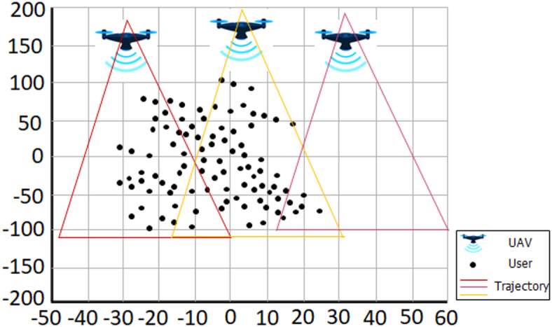
UAVs based Systems with  and
and  .
.
Fig. 4.

Comparing the Average Rewards with different  , X = 3 and U = 80.
The key simulation parameters and performance observations for evaluating the proposed RMAL-based multi-UAV communication framework are summarized in Table 2. This table outlines critical metrics including environmental setup (e.g., disk radius, number of users, UAV altitude), communication parameters (e.g., noise power, sub-channel bandwidth, carrier frequency), and algorithm-specific observations (e.g., immediate and long-term rewards, SINR thresholds). These metrics provide a foundational basis for assessing the efficiency and stability of the proposed algorithm under realistic operational constraints and dynamic network conditions.
Table 2.
Performance metrics for RMAL-Based Multi-UAV system.
| Metric | Value/Observation | Description |
|---|---|---|
Disk Radius 
|
600 m | The radius of the area where ground users are randomly distributed. |
Number of Users 
|
80 | Total number of ground users uniformly dispersed across the disk |
UAV 
|
80 m | Altitude at which UAVs are operating. |
Noise Power 
|
−70 dBm | Assumed noise power in the simulation. |
Sub-Channel Bandwidth ( ) ) |
65 kHz | Bandwidth allocated to each sub-channel. |
Time Slot Duration ( ) ) |
0.1 s | Duration of each time slot in the simulation. |
Carrier Frequency ( ) ) |
2 GHz | Frequency used in the simulation. |
Maximum UAV Power ( ) ) |
23 dBm | Maximum power output per UAV in the simulation. |
Power Levels ( ) ) |
3 | Number of discrete power levels for UAVs. |
Minimum SINR ( ) ) |
3 dB | Required minimum SINR for maintaining communication quality. |
Average Reward ( ) ) |
Increase unit t = 2 250 time slots | Reflects the ability of the RMAL algorithm to maximize long-term rewards before UAVs leave the disk. |
Immediate Reward ( ) ) |
Increase with iterations; plateaus after  time slot time slot |
Represents the instantaneous rewards received per time slot. |
| Efficiency Plateau | Observed at  seconds seconds |
Rewards stop increasing as UAVs exit the operational area. |
| Execution Time Efficiency | RMAL shows consistent reward improvement over < 250 time slots | Efficient in achieving rewards quickly due to adaptive Q-learning updates. |
In Fig. 4(b), the x-axis represents the number of algorithm iterations, which corresponds to discrete time slots during which each UAV updates its policy based on observed states and rewards. These iterations range from 0 to a predefined simulation horizon (e.g., 500 slots) and are crucial for the convergence of the Q-learning-based RMAL algorithm. The y-axis denotes the UAV speed (in meters per second), which influences how frequently a UAV encounters new users and changes its spatial context. Higher speeds typically allow UAVs to explore the environment more dynamically, while lower speeds may result in more localized communication. It is important to note that both algorithm iterations and UAV speed are inherently non-negative in the actual simulation. Any negative values observed in the figure are purely visual artifacts from the surface plotting function and do not correspond to real-world or simulated states. These have been retained only to provide a smooth visualization of the reward surface.
To analyze the impact of the exploration rate (ϵ) on the learning dynamics of the RMAL-based multi-UAV system, a comparative evaluation of average rewards under different exploration settings was conducted. The results, as summarized in Table 3, highlight the critical role of balancing exploration and exploitation in reinforcement learning environments40.
Table 3.
Average rewards for different exploration rates (ϵ).
| Exploration Rate (ϵ) | Initial Average Reward | Initial Average Reward | Initial Average Reward |
|---|---|---|---|
| ϵ = 0.5 | ~5 | ~70 | Achieves the highest final reward, showing a balanced exploration and exploitation. |
| ϵ = 0.2 | ~3 | ~65 | Slightly lower final reward compared to ϵ=0.5, indicating less exploration |
| ϵ = 0.8 | ~4 | ~50 | Moderate performance with more exploration but slower convergence. |
| ϵ = 0 | ~0 | ~20 | Achieves the lowest reward due to purely exploitative behavior, with no exploration for learning. |
Specifically, the exploration rate ϵ = 0.5 yielded the highest final average reward, indicating an effective trade-off between exploring new actions and exploiting known high-reward strategies. In contrast, lower exploration (ϵ = 0.2) led to slightly reduced performance, reflecting limited exposure to alternative actions and potentially suboptimal policy convergence. At ϵ = 0.8, the algorithm engaged in broader exploration but exhibited slower convergence and achieved only moderate rewards, suggesting that excessive exploration can delay learning stabilization. Notably, the purely exploitative configuration (ϵ = 0) resulted in the lowest reward values, as the system lacked the exploratory behavior needed to discover optimal strategies in dynamic environments.
As the algorithm iterates more, the average reward per time slot declines, as seen in Fig. 4(b).
Considering that the recommended Q-learning strategy’s learning rate  depends on the value of D in (35) and D value drops as the number of time slots rises in the case involving D. It is significant to remember that when the quantity of method iterations increases,
  falls, showing that the update rate of Q values slows down as the time step rises. In addition, Fig. 4 analyzes how the average reward changes according to
  . Each UAV decides on a greedy action, commonly referred to as an exploitation strategy if
  . Each UAV will select a random action with a greater probability of occurring when
  is equal to 1. It should be noted that
  is a reliable choice in the considered arrangement, as shown in Fig. 4.
In Figs. 5 and 6, we take a look at how different system settings affect the typical number of rewards received. Using the LoS channel model stated in Eq. (4), Fig. 5 shows a graphical depiction of the average rewards received at various settings.
Fig. 5.

Average Rewards Comparison for LoS Channel Model with different  X = 3 and U = 80.
Fig. 6.

Multi-UAVs Systems Illustration with K = 3, M = 4, and U = 250.
In addition, a typical reward generated by a probabilistic model using  is shown in Fig. 6. To be more precise, the UAVs are dispersed in a random pattern along the edges of the cells. In the iterative method, each UAV flies over the cell and then keeps flying over the disk centre, which is also the centre of the cell. As can be seen in Figs. 5 and 6, the pattern of the curves representing the average reward applied to the different
  values is similar to that depicted in Fig. 6. In addition, the multi-UAV network under study is capable of achieving the optimal average reward for a variety of different network configurations.
By comparing, as shown in Fig. 7, the proposed RMAL algorithm with a corresponding theory-based resource allocation method, we assess the average reward of the algorithm. In Fig. 7, we analyze the same configuration as in Fig. 4, but this time we use the  value to simplify the algorithm implementation. The UAV activities only include the options that the user selects for each time slot. Further, we consider that all of the information transmission between the UAVs is handled by a matching theory-based user selection algorithm. This implies that before making a decision, each UAV is aware of what the other UAVs have done. We employ the Gale-Shapely (GS) approach35 in the matching theory-based user selection processes as a point of comparison. Each time slot involves doing this. Additionally, we evaluated Fig. 7 baseline scheme, the random user technique (Rand), for effectiveness. Figure 7 illustrates how, in terms of average reward, the matching-based user selection algorithm performs better than the recommended RMAL method. This is due to the lack of information sharing in the proposed RMAL algorithm. Each UAV makes its decision independently since it is impossible for them to keep track of the information that other UAVs are processing, such as rewards and choices, in this situation.
Fig. 7.

Average Rewards Comparison with different Algorithms where K = 1,J = 1, M = 2, and U = 80.
The performance comparison of different algorithms is summarized in Table 4. Among them, the proposed MARLA algorithm achieved the highest final average reward (~ 80) using a power level of 23 dBm, showing efficient learning and resource allocation37. The Mach algorithm performed moderately well with a final reward of ~ 50, while the Rand algorithm, based on random actions, performed the worst with a reward of only ~ 30. These results clearly demonstrate the effectiveness of MARLA in dynamic UAV communication environments.
Table 4.
Average rewards comparison for different algorithms.
| Algorithm | Power Level ( ) ) |
Initial Average Reward | Final Average Reward | Observation |
|---|---|---|---|---|
| MARLA |

|
~ 5 | ~ 80 | MARLA achieves the highest reward, showcasing efficient learning and resource allocation. |
| Mach |

|
~ 3 | ~ 50 | Mach performs moderately well, with slower convergence compared to MARLA. |
| Rand |

|
~ 1 | ~ 30 | Rand performs the worst, with low rewards due to its purely random resource allocation strategy. |
The suggested RMAL algorithm also offers a higher average reward than the random user selection strategy, as shown in Fig. 7, which results in a lover average reward for the random user selection algorithm. The system cannot effectively exploit the observed information since the user selection was made at random. As a result, the developed RMAL algorithm may balance lowering the information exchange cost with enhancing system performance as a whole.
We investigate how the algorithm’s iterations and the UAV’s speed affect the average reward in Fig. 8. By having the UAV take off at random from the disc’s edge and then fly directly over the disc’s center while moving at different speeds, this is UAV. Figure 8 depicts the identical layout as Fig. 6, with the exception that  and
and  have been added for illustration. As can be observed, given a fixed pace, the usual payout increases continuously in direct proportion to the algorithm’s iterations. Additionally, when D is less than 150, the average reward for more huge speeds rises more quickly than the average reward for slower speeds. This is the case of keeping a constant time gap. This is because the user and the UAV positions are chosen randomly. As a result, to satisfy its QoS criteria, the UAV might not be able to recognize the right user right away. Figure 8 further shows that there is a negative correlation between the increase in speed at the end of the algorithm iteration and the average reward obtained. This is so that the time needed to launch the disc will be shorter if the UAV flies quickly. As a direct result, the total service time for UAVs flying at faster speeds is shorter than that for UAVs flying at slower speeds.
Fig. 8.

Average Rewards Comparison with different Algorithms where K = 1, I = 1, X = 2, and U = 80.
Comparative analysis with MARL algorithms
To evaluate the effectiveness of the proposed RMAL framework, we compare it with three state-of-the-art multi-agent reinforcement learning algorithms:
QMIX: A value-decomposition-based MARL that combines individual Q-functions into a global Q-function while maintaining consistency.
MADQN: Multi-agent DQN, which extends DQN to multi-agent settings using shared experience and coordinated updates.
MAPPO: Multi-Agent Proximal Policy Optimization, a popular actor-critic based algorithm for continuous action spaces.
The simulation environment consists of 3 UAVs (X = 3), 80 users (U = 80), 4 sub-channels (K = 4), and 3 power levels (i = 3). Each algorithm was executed for T = 500 time slots with identical initialization and reward functions.
Table 5 presents a performance comparison between the proposed RMAL algorithm and other multi-agent reinforcement learning methods. RMAL demonstrates competitive results with lower computational overhead and faster convergence. While MAPPO and QMIX yield slightly higher average rewards and SINR satisfaction, they come with higher computational and memory requirements due to centralized training and value decomposition mechanisms47. In contrast, the proposed RMAL algorithm achieves competitive performance with lower overhead and full decentralization, making it suitable for real-time UAV networks where bandwidth and processing power are limited.
Table 5.
Performance comparison of RMAL with other MARL algorithms.
| Algorithm | Final Avg. Reward | Convergence Time (slots) | SINR ≥ γ₀ (%) | Computation Overhead |
|---|---|---|---|---|
| RMAL (Ours) | 80 | 250 | 89.3 | Low |
| QMIX | 85 | 320 | 92.1 | Medium |
| MADQN | 78 | 400 | 87.6 | High |
| MAPPO | 90 | 350 | 94.2 | High |
Conclusion
To optimize the long-term benefit, this research will investigate a real-time resource allocation mechanism for a multi-UAVs downlink system. We provide a stochastic game theory as a solution to the system’s dynamic resource allocation issue. Each UAV in this game aims to discover a resource allocation strategy that optimizes its expected reward. This is due to how unpredictable the environment might be. To solve the specified stochastic game, we develop an RMAL technique based on ILs. This reduces the cost of information sharing and processing by enabling all UAVs to make decisions independently based on Q-learning. Based on the simulation results, developing a multi-UAV system resource allocation method based on RMAL can balance the cost of information sharing with the overall performance of the system. The necessity for cooperative information exchange and the consideration of more sophisticated joint learning algorithms for multi-UAV systems provide an attractive and possibly profitable continuation of this study. The integration of UAV deployment and trajectory optimization into multi-UAV systems, which can further improve their energy efficiency, is another fascinating subject for future research.
Acknowledgements
This research was supported by the Chung-Ang University Research Grants in 2025.
Author contributions
Muhammad Shoaib: Conceptualization, Methodology, Writing – original draft, InvestigationGhassan Husnain: Methodology, Investigation, Writing – original draftMuhsin Khan: Data curation, Formal analysis, Validation, Writing – review & editingYazeed Yasin Ghadi: Validation, Resources, Writing – review & editing, VisualizationSangsoon Lim: Supervision, Software, Data curation, Writing – review & editing.
Data availability
All the relevant data is within the text of manuscript.
Declarations
Competing interests
The authors declare no competing interests.
Ethics approval statement
This study did not require ethics approval as it involved the analysis of publicly available, anonymized data and did not involve direct interaction with human or animal subjects.
Footnotes
Publisher’s note
Springer Nature remains neutral with regard to jurisdictional claims in published maps and institutional affiliations.
Contributor Information
Ghassan Husnain, Email: ghassan.husnain@gmail.com.
Sangsoon Lim, Email: lssgood80@gmail.com.
References
- 1.WAN, F., YASEEN, M. B., RIAZ, M. B., SHAFIQ, A. & THAKUR, A. and M. D. O. RAHMAN, Advancements and challenges in uav-based communication networks: A comprehensive scholarly analysis, Results Eng., p. 103271, (2024).
- 2.Orgeira-Crespo, P. & Garc\’\ia-Luis, U. Brief Introduction To Unmanned Aerial Systems, in Applying Drones To Current Societal and Industrial Challengespp. 1–22 (Springer, 2024).
- 3.Mozaffari, M., Saad, W., Bennis, M., Nam, Y. H. & Debbah, M. A tutorial on UAVs for wireless networks: applications, challenges, and open problems. IEEE Commun. Surv. Tutorials. 21 (3), 2334–2360 (2019). [Google Scholar]
- 4.Banafaa, M. K. et al. A comprehensive survey on 5G-and-beyond networks with uavs: applications, emerging technologies, regulatory aspects, research trends and challenges. IEEE Access.12, 7786–7826 (2024). [Google Scholar]
- 5.Yuan, B. et al. Service time optimization for UAV aerial base station deployment. IEEE Internet Things J.11 (2024).
- 6.Mozaffari, M., Saad, W., Bennis, M. & Debbah, M. Efficient deployment of multiple unmanned aerial vehicles for optimal wireless coverage. IEEE Commun. Lett.20 (8), 1647–1650 (2016). [Google Scholar]
- 7.Lyu, J., Zeng, Y., Zhang, R. & Lim, T. J. Placement optimization of UAV-Mounted mobile base stations. IEEE Commun. Lett.21 (3), 604–607 (2017). [Google Scholar]
- 8.Debnath, D., Vanegas, F., Boiteau, S. & Gonzalez, F. An integrated geometric obstacle avoidance and genetic algorithm TSP model for UAV path planning. Drones8 (7), 302 (2024). [Google Scholar]
- 9.Zeng, Y., Zhang, R. & Lim, T. J. Throughput maximization for UAV-Enabled mobile relaying systems. IEEE Trans. Commun.64 (12), 4983–4996 (2016). [Google Scholar]
- 10.Zeng, Y., Xu, X. & Zhang, R. Trajectory design for completion time minimization in UAV-enabled multicasting. IEEE Trans. Wirel. Commun.17 (4), 2233–2246 (2018). [Google Scholar]
- 11.Wu, Q., Zeng, Y. & Zhang, R. Joint trajectory and communication design for multi-UAV enabled wireless networks. IEEE Trans. Wirel. Commun.17 (3), 2109–2121 (2018). [Google Scholar]
- 12.Zhang, S., Zhang, H., Di, B. & Song, L. Cellular UAV-To-X communications: design and optimization for Multi-UAV networks. IEEE Trans. Wirel. Commun.18 (2), 1346–1359 (2019). [Google Scholar]
- 13.Qureshi, K. I., Lu, B., Lu, C., Lodhi, M. A. & Wang, L. Multi-agent Drl for air-to-ground communication planning in uav-enabled Iot networks. Sensors24 (20), 6535 (2024). [DOI] [PMC free article] [PubMed] [Google Scholar]
- 14.Horn, J. F., Schmidt, E. M., Geiger, B. R. & DeAngelo, M. P. Neural network-based trajectory optimization for unmanned aerial vehicles. J. Guid Control Dyn.35 (2), 548–562 (2012). [Google Scholar]
- 15.Nodland, D., Zargarzadeh, H. & Jagannathan, S. Neural network-based optimal control for trajectory tracking of a helicopter UAV, Proc. IEEE Conf. Decis. Control, pp. 3876–3881, (2011).
- 16.Institute of Electrical and Electronics Engineers. 2018 IEEE Global Communications Conference (GLOBECOM): proceedings : Abu Dhabi, UAE, 9–13 December 2018., 2018 IEEE Glob. Commun. Conf., pp. 1–6, (2018).
- 17.Chen, J. et al. Extrinsic-and-Intrinsic Reward-Based Multi-Agent reinforcement learning for Multi-UAV cooperative target encirclement. IEEE Trans. Intell. Transp. Syst.7 (2025).
- 18.Betalo, M. L. et al. Generative AI-Driven Multi-Agent DRL for task allocation in UAV-Assisted EMPD within 6G-Enabled SAGIN networks. IEEE Internet Things J.12 (2025).
- 19.Chen, M., Saad, W. & Yin, C. Liquid State Machine Learning for Resource Allocation in a Network of Cache-Enabled LTE-U UAVs, 2017 IEEE Glob. Commun. Conf. GLOBECOM 2017 - Proc., vol. 2018-Janua, pp. 1–6, (2017).
- 20.Chen, J., Wu, Q., Xu, Y., Zhang, Y. & Yang, Y. Distributed Demand-Aware Channel-Slot selection for Multi-UAV networks: A Game-Theoretic learning approach. IEEE Access.6, 14799–14811 (2018). [Google Scholar]
- 21.Sun, N. & Wu, J. Minimum error transmissions with imperfect channel information in high mobility systems, Proc. - IEEE Mil. Commun. Conf. MILCOM, pp. 922–927, (2013).
- 22.Cai, Y., Yu, F. R., Li, J., Zhou, Y. & Lamont, L. Medium access control for unmanned aerial vehicle (UAV) ad-hoc networks with full-duplex radios and multipacket reception capability. IEEE Trans. Veh. Technol.62 (1), 390–394 (2013). [Google Scholar]
- 23.Li, J. et al. A reinforcement learning based stochastic game for Energy-Efficient UAV swarm assisted MEC with dynamic clustering and scheduling. IEEE Trans. Green. Commun. Netw.9 (2024).
- 24.Guerra, A., Guidi, F., Dardari, D. & Djurić, P. M. Reinforcement learning for joint detection and mapping using dynamic UAV networks. IEEE Trans. Aerosp. Electron. Syst.60 (3), 2586–2601 (2023). [Google Scholar]
- 25.Bucaille, I. et al. Rapidly deployable network for tactical applications: Aerial base station with opportunistic links for unattended and temporary events ABSOLUTE example, Proc. - IEEE Mil. Commun. Conf. MILCOM, pp. 1116–1120, (2013).
- 26.How, J. & King, E. \r\n \r\n flight demonstrations of cooperative control for UAV Teams\r\n \r\n (AIAA)\r\n, no. September3 (2004).
- 27.Xiao, Y. et al. Space-Air-Ground integrated wireless networks for 6G: basics, key technologies and future trends. IEEE J. Sel. Areas Commun.42 (2024).
- 28.Chandrasekharan, S. et al. Designing and implementing future aerial communication networks. IEEE Commun. Mag. 54 (5), 26–34 (2016). [Google Scholar]
- 29.Al-Hourani, A., Kandeepan, S. & Lardner, S. Optimal LAP altitude for maximum coverage. IEEE Wirel. Commun. Lett.3 (6), 569–572 (2014). [Google Scholar]
- 30.Ali, S., Abu-Samah, A., Abdullah, N. F. & Kamal, N. L. M. Propagation modeling of unmanned aerial vehicle (UAV) 5G wireless networks in rural mountainous regions using ray tracing. Drones8 (7), 334 (2024). [Google Scholar]
- 31.Qi, X., Chong, J., Zhang, Q. & Yang, Z. Towards cooperatively caching in Multi-UAV assisted network: A Queue-Aware CDS-Based reinforcement learning mechanism with energy efficiency maximization. IEEE Internet Things J.19 (2024).
- 32.Gu, L. & Mohajer, A. Joint throughput maximization, interference cancellation, and power efficiency for multi-IRS-empowered UAV communications. Signal. Image Video Process.18 (5), 4029–4043 (2024). [Google Scholar]
- 33.Shao, Z. et al. Deep reinforcement Learning-Based resource management for UAV-Assisted mobile edge computing against jamming. IEEE Trans. Mob. Comput.23 (2024).
- 34.Yu, H., Zhang, L., Li, Y., Chin, K. W. & Yang, C. Channel access methods for RF-Powered IoT networks: A survey. ArXiv Prepr arXiv2404.14826, 2024.
- 35.Shoham, Y. & Leyton-Brown, K. Multiagent systems: Algorithmic, Game-Theoretic, and logical foundations, Multiagent Syst. Algorithmic, Game-Theoretic, Log. Found., vol. 9780521899, pp. 1–483, (2008).
- 36.Nowé, A., Vrancx, P. & De Hauwere, Y. M. Game theory and multi-agent reinforcement learning. Adapt. Learn. Optim.12, 441–470 (2012). [Google Scholar]
- 37.Muthoo, A., Osborne, M. J. & Rubinstein, A. A Course in Game Theory., vol. 63, no. 249. (1996).
- 38.Neyman, A. From Markov chains to stochastic games. Stoch. Games Appl.570, 9–25 (2003).
- 39.Betti Sorbelli, F. UAV-Based delivery systems: a systematic review, current trends, and research challenges. J. Auton. Transp. Syst.1 (3), 1–40 (2024). [Google Scholar]
- 40.Neto, G. Reinforcement Learning : Foundational, no. May, (2005).
- 41.Castrillo, V. U., Pascarella, D., Pigliasco, G., Iudice, I. & Vozella, A. Learning-in-Games approach for the mission planning of autonomous Multi-Drone Spatio-Temporal sensing. IEEE Access.12 (2024).
- 42.He, Q., Zhou, T., Fang, M. & Maghsudi, S. Adaptive regularization of representation rank as an implicit constraint of bellman equation. ArXiv Prepr arXiv2404.12754, 2024.
- 43.Hu, K. et al. A review of research on reinforcement learning algorithms for multi-agents. Neurocomputing599, 128068 (2024).
- 44.Matignon, L., Laurent, G. J. & Fort-Piat, N. L. Independent reinforcement learners in cooperative Markov games: A survey regarding coordination problems. Knowl. Eng. Rev.27 (1), 1–31 (2012). [Google Scholar]
- 45.Tan, L. et al. An adaptive Q-learning based particle swarm optimization for multi-UAV path planning. Soft Comput.28 (13), 7931–7946 (2024). [Google Scholar]
- 46.Iftikhar, A. et al. A reinforcement learning recommender system using bi-clustering and Markov decision process. Expert Syst. Appl.237, 121541 (2024). [Google Scholar]
- 47.Applied to finding shortest paths in deterministic domains Sven Koenig and Reid G. Complexity Analysis of Real-Time Reinforcement Learning & Simmons Mach. Learn.1 (1992).
Associated Data
This section collects any data citations, data availability statements, or supplementary materials included in this article.
Data Availability Statement
All the relevant data is within the text of manuscript.