Abstract
Soft, conformable electrical contacts provide efficient, noninvasive probes for the transport properties of chemically and mechanically fragile, ultrathin organic semiconducting films. When combined with high-resolution printing and lamination techniques, these soft contacts also form the basis of a powerful technique for fabricating flexible plastic circuits. In this approach, a thin elastomeric film on a plastic substrate supports the electrodes and interconnections; laminating this substrate against another plastic substrate that supports the gate, dielectric and semiconductor levels establishes effective electrical contacts and completes the circuits. In addition to eliminating many of the problems associated with traditional layer-by-layer fabrication strategies, this lamination scheme possesses other attractive features: the transistors and circuit elements are naturally and efficiently encapsulated, and the active organic semiconductor layer is placed near the neutral mechanical plane. We demonstrate the features of soft, laminated contacts by fabricating large arrays of high-performance thin film transistors on plastic substrates by using a wide variety of organic semiconductors.
Flexible circuits that combine plastic substrates and printing techniques (1) with new classes of organic (2), hybrid organic-inorganic (3), or solution-derived inorganic (4) semiconductors represent important emerging technologies (5). These “plastic” circuits have attractive characteristics that are difficult to achieve with materials and methods used for conventional electronics: they are mechanically flexible, durable, and lightweight, and they can be printed over large areas. They also have the potential to be ultralow in cost partly because they are compatible with continuous, high-speed reel-to-reel fabrication techniques (6–8). As a result, plastic circuits will form the foundations for future devices—electronic paper (9, 10), wearable sensors, low-cost smart cards and radio frequency identification tags, flexible arrays of plastic microphones, etc.—that will complement the types of systems that established electronics supports well (e.g., microprocessors, high-density memory).
Recent results demonstrate several promising combinations of materials and patterning techniques for small-scale (several transistors) to medium-scale (several hundred transistors) plastic circuits (6, 8, 10–12). These systems, however, are fabricated in a general approach that was borrowed from conventional silicon microelectronics: they are built by depositing and patterning one layer of material after another on a single substrate. Designing sets of chemically compatible solution-processable materials that can be reliably deposited on top of plastic substrates and on top of one another in this layer-by-layer approach is challenging. Requirements that follow from this fabrication strategy often lead to transistor and circuit geometries that are not optimized for electrical performance. Similar concerns make it difficult to incorporate designs that improve the mechanical flexibility of the circuits. Efficient and general means for encapsulating the devices are also lacking; their environmental stability is, as a result, typically poor or unknown.
This article introduces a method for using “soft,” conformable electrical contacts and lamination procedures to fabricate printed plastic circuits. In this approach, different parts of a circuit are fabricated on different substrates; at least one of these incorporates high-resolution, conformable electrical contacts. Bonding the substrates together forms embedded, high-performance circuits. This approach has many practical advantages, including the ability (i) to separate many of the patterning and deposition steps, (ii) to enable transistors with geometries that are conducive to high performance, (iii) to produce embedded circuits that are highly resistant to fracture during bending, and (iv) to form completely encapsulated devices. We describe the key features of this method and demonstrate its utility through the fabrication of large area arrays of n- and p-channel transistors with a wide range of organic semiconductors. Measurements show that the mechanical flexibility of these laminated, embedded circuits is excellent. In addition, the encapsulation that automatically follows from the lamination process yields devices that are insensitive to prolonged exposure to demanding operating conditions, including complete immersion in stirred, soapy water.
Materials and Methods
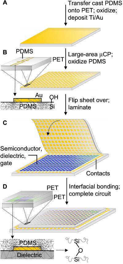
Fig. 1 illustrates the fabrication procedures for circuits similar in layout to those that we recently demonstrated in prototype active matrix electronic paper displays (10). The scheme uses two plastic substrates. One supports conformable transistor source/drain electrodes and appropriate interconnections and the other supports the semiconductor, gate, and dielectric levels. Laminating and permanently bonding these substrates together forms a complete, embedded circuit.
Fig 1.
Schematic illustration of steps for building embedded plastic circuits by lamination. (A) The fabrication begins by transfer casting a thin film of the elastomer PDMS (25–50 μm thick) onto ITO/Mylar (≈175 μm thick), oxidizing the exposed PDMS surface, and depositing uniform layers of Ti (≈1 nm, adhesion promoter) and Au (15–20 nm). (B) μCP on the gold-coated PDMS film defines the transistor source/drain electrodes and related interconnections. The Insets provide magnified views of a pair of source/drain electrodes and a side profile of an electrode. Plasma oxidation produces hydroxyl groups on the exposed surface of the PDMS. (C) Aligning and laminating this sheet to a bottom plastic substrate (PET; ≈175 μm thick) that supports the semiconductor (blue), dielectric (gray), and gate (green) levels produces a complete circuit with top contact transistors. In this case, the contacts at the edges of the bottom sheet enable electrical connection to the embedded circuit. (D) The Insets provide schematic views of a typical transistor and a side profile of a laminated electrode. Finite element modeling qualitatively illustrates conformal contact, or wetting, of the PDMS layer against the dielectric. This wetting is a critical aspect of the lamination approach; it leads to extremely good electrical contacts between the two sheets. Chemical reaction of –Si–OH groups on the PDMS surface with those on the dielectric yield –Si–O–Si– bonds that provide a robust mechanical seal.
The plastic substrates used in this work consist of indium tin oxide (ITO)-coated (100 nm thick) poly(ethylene terephthalate) (PET) sheets (Mylar, ≈175 μm thick; commercially available from Southwall Technologies, Palo Alto, CA). ITO gate electrodes are defined on the substrates by conventional photolithography followed by a concentrated hydrochloric acid etch. An organosilsesquioxane solution is then spin cast on the patterned ITO/PET substrates to form the gate dielectric (32). The substrates are cured at 130°C overnight.
Sylgard 184 polydimethylsiloxane (PDMS) elastomer (used as purchased from Dow Corning, A/B = 1:10) is used on two separate occasions in our lamination approach. It is used to form elastomeric stamps for microcontact printing (μCP). This procedure is well established (13) and will not be described in detail here. Sylgard 184 is also used as a crucial part of the “top” substrate on which the source/drain electrodes and their interconnections are directly printed.
Fabricating the Top Substrate.
The first step (not shown in Fig. 1) involves spin casting a thin (25–50 μm thick) layer of the Slygard 184 PDMS prepolymer against a fluorine-treated flat glass plate. The fluorine treatment involves exposing precleaned glass plates to a vapor of (tridecafluoro-1,1,2,2-tetrahydrooctyl)-1-trichlorosilane (used as purchased from United Chemical Technologies, Bristol, PA) in a dessicator under vacuum for 2 h. The prepolymer is then cured at 70°C overnight. Transferring the cured PDMS from the glass plate onto a plastic substrate requires exposing both the PDMS and the ITO surfaces to an oxygen plasma for 1–2 and 30 s, respectively. In both cases, we used a Plasma-Therm (St. Petersburg, FL) reactive ion etcher with an O2 flow rate of 30 standard cm3/min and a pressure of 30 mtorr at 100 V. Contacting the treated surfaces of the PDMS and the substrate produces an irreversible bond between the PDMS and the ITO (14). Peeling back the PET nondestructively releases the PDMS from the nonstick, fluorinated surface of the glass slide. This transfer casting procedure yields an ultraflat, thin PDMS coating strongly bonded to the PET substrate.
μCP the Drain/Source Level.
Before the uniform deposition of Ti (≈1 nm, at 0.3 nm/s) and Au (≈15 nm, at 1 nm/s), the ultraflat PDMS surface is subjected to another short exposure of plasma oxidation (1–2 s at the same oxidation conditions). The plasma treatment and the deposition of Ti ensure good bonding between the gold and the PDMS: these films easily pass Scotch tape adhesion tests. The thicknesses and deposition conditions were also carefully optimized to minimize any cracking or buckling of the films (15, 16).
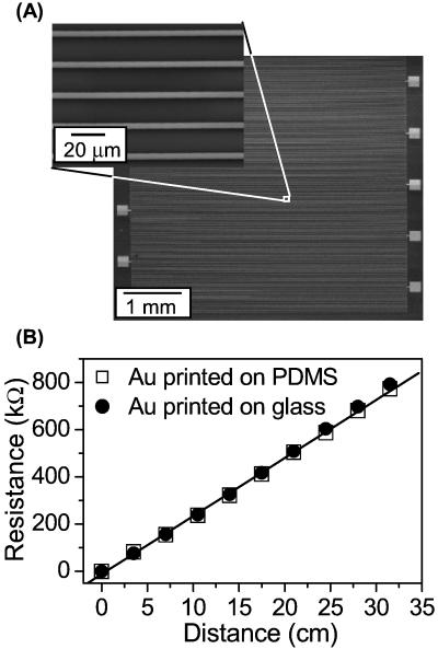
μCP (13, 17) on the Au/Ti produces μm-scale circuit patterns on the PDMS. The rubber stamp in this case has features of relief in the geometry of the source/drain level (i.e., source/drain electrodes and appropriate interconnects) of the circuit. Inking this stamp with a ≈2 mM solution of hexadecanethiol and bringing it into contact with the gold-coated PDMS for ≈1–2 s generates a patterned self-assembled monolayer (SAM) in the geometry of the stamp. An aqueous ferro/ferri cyanide etchant removes the gold not protected by the printed SAM (13). A dilute solution of hydrofluoric acid (≈1% in water) removes the Ti exposed by etching the gold. A final short plasma oxidation step (1–2 s, at the same conditions) produces hydroxyl groups on the exposed surface of the PDMS; it also removes the printed SAM from the gold. The result is μm-sized conducting features of gold strongly bonded to the underlying PDMS. Fig. 2 illustrates the high quality of circuit patterns that can be printed on PDMS in this fashion. The properties of printed wires on PDMS are the same as those on rigid substrates such as glass; the resistivities of the lines in both cases are consistent with literature values (18). However, our experience indicates that μCP generally works better on PDMS than it does on the types of relatively hard substrates (e.g., plastic, glass silicon, etc.) that have been used in the past (13, 17). This finding is likely caused by the conformability of the PDMS substrate, thus facilitating an even better contact with the stamp. These steps complete the fabrication of the top substrate for the laminated circuit.
Fig 2.
(A) Scanning electron micrographs of a microcontact printed test structure that consists of a continuous 5 μm wide × 35 cm long gold wire (15 nm thick) with 10 probing pads (1 × 1 mm squares) on a piece PDMS. (Inset) The sharp, uniform printed lines of this pattern. (B) Measured resistance as a function of wire length for printed patterns on glass (□) and PDMS (•). The slopes in both cases yield resistivities of 2 × 10⁻⁵ Ω⋅cm, consistent with literature values for gold films with thicknesses in the range of 15 to 20 nm. These data illustrate that μCP can form dense, defect-free patterns of gold with μm feature sizes on PDMS.
Fabricating the Gate, Dielectric, and Semiconductor Levels.
A different sheet of PET forms a “bottom” substrate that supports the other parts of the circuit. In this case, gate (ITO, green in Fig. 1), dielectric (spin-on glass, gray), and organic semiconductor (blue) levels were deposited and patterned by using procedures as described (10). In general, this substrate may also provide some source/drain level interconnects and/or contact pads and vias for interfacing the circuit to other external components (e.g., other circuits, power sources, etc.).
Lamination.
Aligning the top substrate with the bottom one, and then bringing them together completes the circuit. Initiating contact at an edge by slightly bending one of the substrates, and then allowing contact to proceed gradually across the circuit provides a convenient way to laminate over large areas without creating trapped air pockets. A critically important requirement for this lamination process is that the top substrate establishes conformal, atomic-scale contact with the bottom substrate over the entire area of the circuit. The thin layer of PDMS elastomer is the essential component for this process. It “wets” the bottom substrate to enable this intimate contact without the use of external pressure to force the two parts together (19). This wetting yields (i) efficient electrical contact of source/drain electrodes on the top substrate with semiconductor layers on the bottom substrate and (ii) strong interfacial bonds that form from a dehydration reaction (14) between the exposed hydroxyl groups on the two substrates (e.g., the PDMS and the spin-on glass for the top and bottom substrates, respectively). This single elastomer-based lamination step produces the circuit and simultaneously embeds it between the two sheets of PET without the use of conventional adhesives.
Results and Discussion
Electrical Characteristics of Devices.
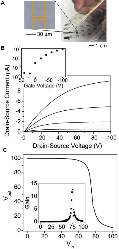
Fig. 3A shows images of a laminated circuit, and Fig. 3B presents the electrical characteristics of a typical transistor that uses pentacene as the semiconductor. The effective mobility of this (≈0.3 cm2/Vs) and other devices fabricated in this fashion was computed from the slope of the variation in the square root of the saturation current with increasing gate voltage (20). Its on/off ratio (≈106) is also comparable to that observed in the best transistors that use this combination of materials with gold source/drain electrodes evaporated directly on top of the semiconductor through a shadow mask (i.e., top contact transistors). In fact, we observed excellent properties (mobilities, threshold voltages, on/off ratios, etc.) in the laminated transistors with every organic semiconductor that we tested: solution-cast regioregular poly(3-hexylthiophene) (p-type) (21) and evaporated films of pentacene (p-type) (22), α-sexithiophene (p-type) (23), dihexyl pentathiophene (p-type) (24), copper phthalocyanine (p-type) (25), copper hexadecafluorophthalocyanine (F16CuPc, n-type) (26), and several different oligofluorenes (27). In all cases the electrical properties of the laminated transistors are similar to those observed in top contact devices that used shadow mask Au electrodes deposited directly on the semiconductors.
Fig 3.
(A) Image of a laminated circuit, and a magnified view of source/drain electrodes (gold) laminated against a layer of pentacene (blue). (B) Current-voltage characteristics of an organic transistor similar to the one that appears in the micrograph above. (Inset) The saturated source/drain current as a function of gate voltage. The on/off ratio is ≈106, and the computed effective mobility is ≈0.3 cm2/Vs. Both of these characteristics are similar to those of the best top contact devices fabricated in the usual way. (C) Transfer characteristics of a laminated complementary inverter circuit that uses pentacene and F16CuPC as the p- and n-type semiconductors, respectively. The gain is ≈14 based on the slope of the curve.
Conventional top contact devices, however, have the disadvantage that they are mechanically fragile: they use source/drain electrodes that rest on top of a semiconductor layer that is typically not bonded to the underlying dielectric. High-resolution devices are also difficult to fabricate because of the sensitivity of the semiconductors to resists, developers, and solvents used in most lithographic techniques for defining the source and drain (10, 28). Bottom contact devices, on the other hand, are mechanically robust (they use semiconductor layers deposited on top of source/drain electrodes that are strongly bonded to the dielectric) and they can be fabricated easily by depositing the semiconductor onto lithographically prepatterned electrodes. It is difficult, however, to achieve high electrical performance in these devices, partly because crystallization and wetting of the semiconductor at the edges of the source/drain electrodes lead to poor electrical properties (e.g., effective mobility) near the location where charge injection occurs (10). The laminated devices avoid these problems. They combine the good electrical performance of top contact transistors with the mechanical stability of bottom contact devices, in a format that separates lithographic preparation of the source/drain electrodes from the semiconductor.
Fig. 3C shows the transfer characteristics of a laminated organic complementary inverter circuit that uses pentacene and F16CuPc (see Inset for the gain) for the p- and n-channel transistors, respectively. Its performance is the same as similar, but larger-scale, top contact devices fabricated by conventional shadow masking.
Mechanical Flexibility of Devices.
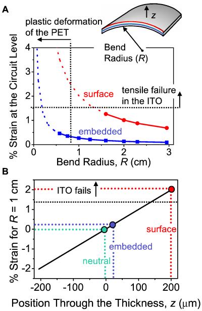
In addition to providing mechanically stable, high-quality organic transistors and circuits, the lamination approach yields embedded devices with much better mechanical flexibility than top or bottom contact circuits fabricated on the surfaces of substrates (i.e., surface circuits) in the usual way. Fig. 4 compares the bending strains at the circuit levels of surface and embedded devices. The surface circuit uses a ≈400-μm PET substrate (two ≈175-μm PET sheets bonded together by a thin layer of PDMS), and the embedded circuit uses ≈175 μm PET for the top and bottom substrates. The ITO gate is the most brittle material in these systems; its fracture limits the mechanical flexibility. The symbols in Fig. 4A correspond to bend radii (R) at which the ITO remains electrically continuous. The surface circuit fails because of electrical opens that appear in the ITO layer for R < ≈1.5 cm. The embedded circuit does not fail until well after the PET plastically deforms near R ≈ 0.75 cm. Fig. 4B illustrates the approximate mechanical strains as a function of position through the thickness of the devices at R = 1 cm. To compute the tensile strains, we assumed no-slip conditions between layers and that the bend radius is much greater than the total thickness of the circuit (29). The embedded circuit has good mechanical flexibility because it lies near the neutral mechanical plane (30). It is straightforward to design the system to place the embedded circuit precisely on the neutral plane. A practical consequence of this embedded construction is that it can yield circuits whose bendability is limited by the plastic substrates rather than the mechanical properties of the semiconductors, conductors, or dielectrics of the circuit. This result, combined with the ease of achieving the required embedded geometry by lamination, will expand significantly the range of materials that can be considered for flexible circuits. We note that it is possible to increase the mechanical flexibility of a circuit by reducing the thickness of the substrate. The practical utility of this approach, however, is limited because many potential applications require the circuits to have some degree of flexural rigidity.
Fig 4.
(A) Calculated strain in laminated, embedded circuits (blue) and conventional surface circuits (red) as a function of bend radius (R). The symbols correspond to devices that were tested and found to be electrically functional. The total thicknesses of the completed circuits (including their supports) were the same (≈400 μm PET with PDMS wetting layers) in both cases. (Inset) Schematic illustration of the geometries. The most brittle material in the circuits is the ITO gate. This layer cracks and forms electrical opens at tensile strains greater than ≈1.5%. This critical strain is achieved at R ≈1.5 cm in the case of the surface circuit; it occurs at R < ≈0.75 cm in the embedded circuit. In this latter case, the PET plastically deforms before the ITO fails. This result suggests that embedded systems can be designed so that the mechanical properties of the electronic materials do not limit the bendability of the devices. This feature will expand significantly the range of candidate electronic materials for flexible circuit applications. (B) Computed strains as a function of position through the thickness at R ≈1 cm. These results illustrate clearly the mechanical advantages of embedded circuits formed by lamination.
Encapsulation.
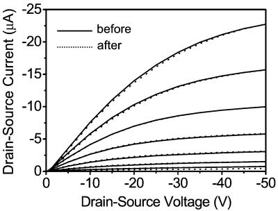
Embedded circuits also have the advantage that they are naturally encapsulated. This aspect has practical importance, particularly since many organic semiconductors are highly sensitive to their environment: they have, in fact, some promise as efficient detecting elements in electronic vapor sensors (31). As an example of the efficacy of the encapsulation that results from lamination, Fig. 5 presents current-voltage characteristics of a pentacene transistor (located within ≈1 mm of the edge of the test structure) before and after complete immersion for 15 min in a stirred bath of water with a high (2.5 wt%) concentration of a detergent designed for cleaning laboratory glassware (Liqui-Nox, SPI Supplies, West Chester, PA). These data illustrate negligible changes in the transistor properties. Under similar conditions, conventional, unencapsulated devices fail after ≈30 s because of complete delamination of the semiconductor and dielectric layers. The properties of embedded transistors degrade slightly (on currents lower by ≈1.5 times) after immersion for several hours. The plastic materials used here, however, are not designed to form a fully hermetic seal. Nevertheless, their remarkable ability to provide a water and moisture barrier at the level illustrated in Fig. 5 is sufficient even for demanding applications.
Fig 5.
Characteristics of a laminated, embedded plastic transistor before (solid lines) and after (dashed lines) complete immersion in a stirred bath of detergent (2.5 weight percent of Liqui-Nox) in water for ≈15 min. The data show negligible changes in the electrical properties. Exposing an identical, but unembedded, transistor to the same conditions results in complete delamination of the device within the first ≈30 s because of liftoff of the semiconductor (pentacene) and the dielectric (organosilsesquioxane spin-on glass).
Conclusions
The lamination approach introduced here exploits the unique features of certain materials and patterning techniques that are beginning to emerge for flexible circuit applications. It is enabled by introducing elastomers, a new class of material for plastic electronics, into these systems. This technique has many attractive features and practical advantages; several were demonstrated in this article with organic transistors and simple circuits. The same method may also be suitable for organic light-emitting devices, memory cells, and other systems. It is also compatible with a wide variety of conventional and unconventional patterning techniques and it should scale well into the nanometer regime. Straightforward techniques for introducing via connections will enable complex, multilevel circuits. In addition, the compatibility of the approach with a wide range of organic semiconductors suggests that it may provide a general method for noninvasively establishing efficient electrical contacts to many different types of fragile or ultrathin organic and bio-organic materials. This capability will be useful for basic studies of charge transport in these and other systems.
Acknowledgments
We thank E. Chandross and L. Dhar for helpful discussions.
Abbreviations
ITO, indium tin oxide
PET, poly(ethylene terephthalate)
PDMS, polydimethylsiloxane
μCP, microcontact printing
This paper was submitted directly (Track II) to the PNAS office.
References
- 1.Mirkin C. A. & Rogers, J. A. (2001) MRS Bull. 26, 506-536. [Google Scholar]
- 2.Bao Z., Rogers, J. A. & Katz, H. E. (1999) J. Mater. Chem. 9, 1895-1904. [Google Scholar]
- 3.Kagan C. R., Mitzi, D. B. & Dimitrakopoulos, C. D. (1999) Science 286, 945-947. [DOI] [PubMed] [Google Scholar]
- 4.Ridley B. A., Nivi, B. & Jacobson, J. M. (1999) Science 286, 746-749. [DOI] [PubMed] [Google Scholar]
- 5.Service R. F. (2000) Science 287, 415-417. [Google Scholar]
- 6.Sirringhaus H., Kawase, T., Friend, R., Shimoda, T., Inbasekaran, M., Wu, W. & Woo, E. P. (2000) Science 290, 2123-2126. [DOI] [PubMed] [Google Scholar]
- 7.Rogers J. A., Bao, Z. & Makhija, A. (1999) Adv. Mater. 11, 741-745. [Google Scholar]
- 8.Drury C. J., Mutsaers, C. M. J., Hart, C. M., Matters, M. & de Leeuw, D. M. (1998) Appl. Phys. Lett. 73, 108-110. [Google Scholar]
- 9.Rogers J. A. (2001) Science 291, 1502-1503. [DOI] [PubMed] [Google Scholar]
- 10.Rogers J. A., Bao, Z., Baldwin, K., Dodabalapur, A., Crone, B., Raju, V. R., Kuck, V., Katz, H., Amundson, K., Ewing, J. & Drzaic, P. (2001) Proc. Natl. Acad. Sci. USA 98, 4835-4840. [DOI] [PMC free article] [PubMed] [Google Scholar]
- 11.Kane M. G., Campi, J., Hammond, M. S., Cuomo, F. P., Greening, B., Sheraw, C. D., Nichols, J. A., Gundlach, D. J., Huang, J. R., Kuo, C. C., et al. (2000) IEEE Electron. Dev. Lett. 21, 534-536. [Google Scholar]
- 12.Rogers J. A., Bao, Z., Dodabalapur, A., Schueller, O. J. A. & Whitesides, G. M. (2000) Synth. Met. 115, 5-11. [Google Scholar]
- 13.Kumar A. & Whitesides, G. M. (1993) Appl. Phys. Lett. 63, 2002-2004. [Google Scholar]
- 14.Schueller O. J. A., Duffy, D. C., Rogers, J. A., Brittain, S. T. & Whitesides, G. M. (1999) Sens. Act. A 78, 149-159. [Google Scholar]
- 15.Bowden N., Brittain, S., Evans, A. G., Hutchinson, J. W. & Whitesides, G. M. (1998) Nature (London) 393, 146-149. [Google Scholar]
- 16.Huck W. T. S., Bowden, N., Onck, P., Pardoen, T., Hutchinson, J. W. & Whitesides, G. M. (2000) Langmuir 16, 3497-3501. [Google Scholar]
- 17.Xia G. M., Zhao, X. M., Kim, E. & Whitesides, G. M. (1995) Chem. Mater. 7, 2332-2337. [Google Scholar]
- 18.Larson D. C. (1971) in Physics of Thin Solid Films, eds. Francombe, M. H. & Hoffman, R. W. (Academic, New York), Vol. 6, pp. 81–149. [Google Scholar]
- 19.Jacobs H. O. & Whitesides, G. M. (2001) Science 291, 1763-1766. [DOI] [PubMed] [Google Scholar]
- 20.Sze S., (1985) Semiconductor Devices: Physics and Technology (Wiley, New York), pp. 204–206.
- 21.Bao Z., Dodabalapur, A. & Lovinger, A. J. (1996) Appl. Phys. Lett. 69, 4108-4110. [Google Scholar]
- 22.Gundlach D. J., Lin, Y. Y. & Jackson, T. N. (1997) IEEE Electron. Dev. Lett. 18, 87-89. [Google Scholar]
- 23.Katz H. E., Torsi, L. & Dodabalapur, A. (1995) Chem. Mater. 7, 2235-2237. [Google Scholar]
- 24.Li W., Katz, H. E., Lovinger, A. J. & Laquidanum, J. G. (1999) Chem. Mater. 11, 458-465. [Google Scholar]
- 25.Bao Z., Lovinger, A. J. & Dodabalapur, A. (1996) Appl. Phys. Lett. 69, 3066-3068. [Google Scholar]
- 26.Bao Z., Lovinger, A. J. & Brown, J. (1998) J. Am. Chem. Soc. 120, 207-208. [Google Scholar]
- 27.Meng H., Bao, Z. N., Lovinger, A. J., Wang, B. C. & Mujsce, A. M. (2001) J. Am. Chem. Soc. 123, 9214-9215. [DOI] [PubMed] [Google Scholar]
- 28.Kymissis I., Dimitrakopoulos, D. C. & Purushothaman, S. (2001) IEEE Trans. Electron. Dev. 48, 1060-1064. [Google Scholar]
- 29.Ugural A. C., (1999) Stresses in Plates and Shells (McGraw–Hill, Boston), pp. 266–268.
- 30.Suo Z., Ma, E. Y., Gleskova, H. & Wagner, S. (1999) Appl. Phys. Lett. 74, 1177-1179. [Google Scholar]
- 31.Torsi L., Dodabalapur, A., Sabbatini, L. & Zambonin, P. G. (2000) Sens. Act. B 67, 312-316. [Google Scholar]
- 32.Bao, Z., Kuck, V., Rogers, J. A. & Paczkowski, M. A. (2002) Adv. Funct. Mater., in press.


