

ABSTRACT
Electrochemical CO2 electrolyzers are increasingly recognized for their potential to convert CO2 into valuable chemical feedstocks, addressing critical environmental and economic challenges. Traditionally, the catalytic properties of the cathode, where CO2RR directly occurs, have been the main focus of research due to their control over product selectivity. More recently, however, membrane‐based electrolyzers—commonly used in fuel cells and water electrolyzers—have shown substantial potential for commercial CO2 reduction, offering improved scalability and efficiency. Nevertheless, the complex components in membrane‐based electrolyzers require precise optimization, as each unit directly impacts system performance and product selectivity. In this review, the structures and components of membrane‐based CO2 electrolyzers are systematically examined, including the electrolyzer design, flow channels, membranes, electrolytes, CO2 supply units, and electrodes. Recent innovations in the optimization of these components are highlighted to provide insights into advancing CO2RR technology toward commercially feasible applications. This approach can assist considerably in improving the CO2RR electrolyzer performance, thereby helping predict optimal pathways for commercial realization and guide future development.
Keywords: CO2 reduction reaction, CO2 electrolyzer, flow channel, membrane, porous transfer electrode
This review discusses how each component of a CO2 electrolyzer, such as membranes, electrodes, electrolytes, flow channels, and inlet CO2 affects system performance. By analyzing recent advances and design strategies, it highlights how optimized component selection can improve efficiency and product selectivity. These insights provide practical guidance for designing CO2 electrolyzers suited for industrial‐scale applications.

1. Introduction
Advances in the power generation, manufacturing, and transportation industries have accelerated greenhouse gas emissions. Consequently, the atmospheric concentration of CO2 is expected to reach 570 ppm by 2100, which could exacerbate adverse environmental issues such as global warming [1, 2, 3, 4]. The temporary reduction in CO2 emissions during the COVID‐19 pandemic demonstrates that proactive actions and close global cooperation can aid in mitigating the climate crisis [5, 6]. Previous efforts to reduce the atmospheric CO2 concentration were primarily focused on carbon capture and storage (CCS) technologies. However, to overcome the effectiveness‐ and sustainability‐related concerns of CCS technologies, interest in carbon capture, utilization, and storage schemes is increasing [7, 8]. Among the various CO2 conversion methods, the electrochemical method for converting CO2 into valuable chemicals and fuels is the most promising because it can be performed under mild conditions (room temperature and atmospheric pressure) and it permits storage of electricity and that of CO2 as liquid and gas fuels in a relatively high ratio [9]. The electrochemical CO2 reduction reaction (CO2RR) converts CO2 into useful products including C1 products including CO, HCOOH, CH4, and CH3OH, and C2+ products including C2H4, C2H5OH, CH3COOH, and C3H7OH [10]. Additionally, the use of electrochemical CO2RR systems allows the captured CO2 to be collected and recycled, enabling an effective carbon cycle. As renewable energy sources such as solar, wind, and geothermal energy are becoming increasingly more viable and cost‐effective, renewable‐energy‐based CO2 electrolysis is approaching large‐scale commercialization [11].
The performance of electrochemical CO2RR systems has been evaluated using several key metrics [12], with current density, Faradaic efficiency (FE), energy efficiency, and single‐pass conversion efficiency (SPCE) being generally considered. The current density (mA cm−2 or A cm−2) represents the amount of current flowing per unit area of the active electrode, directly indicating the reaction rate. The FE is the percentage of the total current that contributes to the formation of a specific product, reflecting the selectivity of the reaction. The energy efficiency is the ratio of the chemical energy produced to the electrical energy supplied, and serves as a crucial metric for evaluating economic viability [13]. The SPCE represents the percentage of CO2 converted in a single pass through the reactor and is used to evaluate the efficiency of the system and optimize the reactor design [14]. Because the CO2RR can yield various products, enabling high selectivity for the target compound is imperative to facilitate separation. These metrics play a crucial role in increasing the commercial and industrial feasibility of the CO2RR. However, the CO2RR exhibits a low energy efficiency because it requires a cell voltage higher than the theoretical potential. Although the interactions between the electrode and membrane, as well as the correlation between the electrode and the flow channel, have been investigated to address these issues, research on these side systems remains rudimentary [15]. Consequently, the side systems of the CO2RR electrolyzer should be actively studied.
CO2RR systems have evolved from H‐type cells to membrane electrode assembly (MEA)‐type electrolyzers and flow‐type electrolyzers. H‐type cells are primitive electrolyzers comprising two electrolyte‐filled chambers with electrodes positioned at the center of each chamber [16]. Although these cells are simple and useful for testing various catalysts, they have limitations in large‐scale applications owing to their low current density and inefficient CO2 gas delivery [17]. To overcome these issues, research attention shifted to MEA‐type electrolyzers, which integrate polymer electrolyte membranes and porous transfer electrodes (PTEs) to improve the inter‐electrode ion transport, thereby enhancing the current density and energy efficiency [18]. Furthermore, flow‐type electrolyzers were developed to achieve high efficiency, scalability, and effective collection of liquid products [19]. These electrolyzers continuously manage the flow of gases and liquids within the reactor, achieving a high current density and SPCE, rendering them suitable for industrial applications [20]. Additionally, the flow‐type electrolyzers have been designed to collect liquid products effectively, highlighting their superior commercial viability.
Several variables influence the operation of CO2RR systems. The electrolyzer components include the flow channel, PTE, and electrode [21, 22], and the external operational variables include the input CO2 state, flow rate, electrolyte, and pH [23, 24].
This paper reviews recent research on improving the performance metrics of CO2RR systems and overcoming the associated challenges. The characteristics, advantages, and limitations of each cell constituent are detailed. Furthermore, the substances produced and the catalysts used in CO2RR systems are explored. Specifically, membranes, electrolytes, PTEs, and flow channels are examined, and directions for future research are briefly suggested.
2. Important Constituents of CO2RR Systems
2.1. Electrolyzer
Numerous studies have recently been conducted on the CO2RR, and electrolyzers have been selected depending on the purpose of the research. CO2RR electrolyzers are based on the single‐cell and stacked‐cell structures traditionally used in fuel cells and water electrolyzers. As mentioned earlier, CO2RR electrolyzers are typically categorized into: (1) H‐type cells, (2) flow‐type electrolyzers, and (3) MEA‐type electrolyzers (Figure 1 and Table 1). These electrolyzers have unique characteristics but exhibit varying shapes and structures, which can lead to different results even when studying the same catalyst or electrode. Additionally, unlike in fuel cells and water electrolyzers—in which only gas is supplied or only liquid is supplied by reactants, respectively—in CO2RR systems, CO2 gas acts as a reactant in a liquid environment; therefore, the electrolyzer must be selected considering this feature.
FIGURE 1.
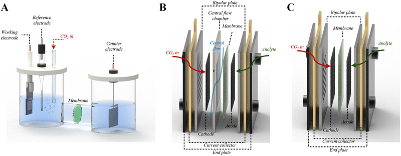
Schematic illustration of CO2RR electrolyzers. (A) H‐type cell, (B) flow‐type electrolyzer, and (C) MEA‐type electrolyzer.
TABLE 1.
Advantages and disadvantages of different types of CO2RR electrolyzers.
| H‐type cells | Flow‐type electrolyzers | MEA‐type electrolyzers | |
|---|---|---|---|
| Advantages |
|
|
|
| Disadvantages |
|
|
|
| CO2 supply | CO2 purging | Humidified gaseous CO2 | |
| PTL on substrate | X | Needs gas diffusion layer | |
| Current density | <35 mA cm−2 geo | >35 mA cm−2 geo | |
| Distance between electrodes | Relatively far | Thickness of catholyte layer | Zero‐gap |
| CO2 flow rate | Low | High | |
| Concentration of electrolyte | High conc. (e.g., 1 M KOH) | Low conc. (e.g., 0.1 M KOH) | |
| Product phase | Gas, liquid |
Gas Liquid (additional apparatus is required) |
|
2.1.1. H‐Type Cells
In electrochemical studies, traditional H‐type cells have been used to conduct the CO2RR [16, 25, 26] because they are easy to operate and receptive to various electrode materials and configurations. The cathode and anode chambers are filled with electrolytes and separated by an ion‐exchange membrane. A proton‐exchange membrane (PEM) is used for testing under acidic or neutral conditions, whereas an anion‐exchange membrane (AEM) is employed for experiments in basic environments. H‐type cells comprise working and reference electrodes, which are located in the cathode chamber, and a counter electrode, which is situated in the anode chamber. Because H‐type cells include a reference electrode, they are mainly used to study the attributes of catalysts incorporated onto substrates, such as intrinsic activity and reaction mechanism. Additionally, unlike in other types of electrolysis such as hydrogen evolution reaction (HER) or oxygen evolution reaction (OER), CO2RR systems in H‐type cells feature CO2, a gas dissolved in the electrolyte, as reactant. Notably, the catholyte is purged with CO2 gas to saturation prior to the experiments, and CO2 gas is bubbled throughout the reaction. The CO2RR in H‐type cells is significantly influenced by the solubility of CO2 in the catholyte. The low solubility of CO2 in aqueous electrolytes (33 mM under ambient conditions) [19, 27] limits the diffusion rate of CO2 to the cathode surface, resulting in mass‐transfer limitations and low current density [28, 29]. Additionally, owing to the physical separation between the cathode and anode, the electrolyte‐filled compartment exhibits significant ohmic losses, reducing the overall energy efficiency of the system.
Certain CO2RR mechanisms are sensitive to conditions such as the local pH; in these cases, the applied potential or current can vary significantly, underlining the suitability of H‐type cells for studying the reaction mechanism. Therefore, H‐type cells should be used as preliminary testing systems to evaluate the reaction rates of catalysts intended for use as cathodes in relevant industrial‐level flow‐type or MEA‐type electrolyzers and to optimize system performance. To design alternative systems for elucidating the performance of flow‐ or MEA‐type electrolyzers, two conditions must be met: (1) CO2 should be supplied as gas from the back of the cathode (Figure 1B), and (2) interactions should occur at the triple‐phase boundary (TPB) of the membrane, catalyst, and CO2 gas in the local region of the cathode.
2.1.2. Flow‐Type Electrolyzers
To address the issues inherent to H‐type cells, such as the solubility of CO2 and ohmic loss of the electrolyte, flow‐type electrolyzers have been devised based on the MEA‐type structures traditionally employed in fuel cells and water electrolyzers [30, 31, 32]. Flow‐type electrolyzers are designed to supply reactants from the back of the electrode using a porous transfer layer (PTL) as the electrode substrate. Thus, in the CO2RR, CO2 is supplied in gas form to the back of the cathode, and a minimally thick catholyte chamber is positioned between the cathode and the membrane to minimize ohmic loss.
In H‐type cells, CO2 diffuses from a distance of over 50 µm to the front of the cathode; however, when CO2 is supplied from the back through the PTL, the diffusion path is shortened to ≈50 nm, significantly increasing mass‐transfer efficiency [12]. Separating the CO2 gas supply and the catholyte flow permits the use of highly alkaline electrolytes, which allows the local pH at the cathode surface to be maintained at a high level; this can suppress the competing HER and promote C–C coupling, resulting in a higher FE for C2+ products [33, 34]. Additionally, it can prevent the formation of salts via the reaction between CO2 and OH−‐containing compounds such as carbonates and bicarbonates. Cu‐based catalysts promote the formation of diverse gaseous and liquid products. This is advantageous because the gaseous products are separated toward the side where CO2 is supplied at the back of the cathode, whereas the liquid products are separated on the catholyte side. However, this separation requires the electrode to be highly hydrophobic to prevent electrolyte flooding at the back of the cathode. Generally, a carbon‐paper‐based microporous layer (MPL)—which is carbon paper coated with polytetrafluoroethylene (PTFE)‐containing carbon particles—is used to address this problem. For instance, Montfort et al. demonstrated that a PTL with superhydrophobic PTFE could significantly reduce flooding [35]. Although superhydrophobic electrodes can mitigate these problems, the nonconductive nature of PTFE leads to a nonuniform current distribution, reducing the system efficiency and stability. Therefore, structurally conductive electrodes with superhydrophobic properties must be developed.
2.1.3. MEA‐Type Electrolyzers
MEA‐type electrolyzers are referred to as zero‐gap electrolyzers because they do not feature the catholyte layer [36, 37]. The cathode and anode are in complete contact with the membrane, which significantly reduces the internal ohmic resistance [38, 39]. CO2 gas is supplied to the catalyst through the back of the cathode PTL, while the anolyte is supplied to the catalyst through the back of the anode PTL for the OER. Thus, flow channels are worth investigating to ensure the smooth supply of reactants to the back of the electrode. The MEA‐type structure completely separates the cathode and anode with a membrane. Because the products are separated on each side, the quality of the membrane significantly influences the performance of the electrolyzer. The products must be adequately separated without crossover, and the necessary ions should be able to move appropriately; furthermore, the membrane must withstand the physical stress caused by the active flow of the reactants and products, and water should be able to move appropriately from the anode to the cathode. This design allows the system to operate at low voltages and high current densities, thereby satisfying industrial requirements. Furthermore, the compactness of MEA‐type electrolyzers, similar to that of fuel cells and water electrolyzers, can be leveraged to expand the electrode area and permit stacking, thereby enabling industrial‐scale applications. However, the structural characteristics of MEA‐type electrolyzers make them conducive to collecting only gaseous products and not liquid products. Therefore, if MEA‐type electrolyzers can be designed to produce gaseous products such as CO, CH4, and C2H4 with high FEs, they can become more commercially viable.
The electrolyzers are generally used by purchasing commercial products (complete CO2 electrolyzer, dioxide materials) (Figure 2A). In addition, some parts of electrolyzers are directly manufactured (using 3D printing) for experiments [21]. In some cases, all parts of the electrolyzer are customized and manufactured for use (Figure 2B). Usually, in such cases, factors like the corrosiveness and physical strength of each part are considered. The optimization of the structure and the selection of materials for each part are also important. Especially for the end plate or bipolar plate that constitutes the flow path (depending on the configuration of the electrolyzer being used), Ti is commonly used when an acidic electrolyte is used, and either Ti or stainless steel is used when an alkaline electrolyte is used. In addition, the material of the anode part, where the oxidation reaction occurs, is sometimes protected by plating Pt or Au on Ti. As a result, when selecting an electrolyzer, it is important to appropriately choose the structure and materials based on the experimental conditions.
FIGURE 2.

(A) Dioxide materials commercial electrolyzer: In the case of the above figure, customized parts are used for in‐situ experiments. Reproduced with permission [21]. Copyright 2023, American Chemical Society. (B) Electrolyzer with all parts customized.
2.2. Flow Channel
Each component of CO2RR electrolyzers must be optimized to achieve high reactivity. Advances in CO2RR electrode design have led to higher current densities, thereby helping boost industrial applicability [40, 41]. As the electrode area has been enhanced, the mass transport of the reactants and products has increasingly affected the current density and FE. Both MEA‐type and flow‐type electrolyzers have flow channels for supplying CO2 gas to the back of the cathode, with the latter also featuring an additional central channel for catholyte flow [42]. Each channel supplies reactants and emits products; therefore, a flow channel structure that enables a smooth supply of reactants and emissions of products is essential for achieving high performance. The gas flow channel directly transmits electricity to the PTE and compresses the MEA. Additionally, the flow channel in the anode compartment typically carries electrolytes such as KOH, H2SO4, and KHCO3. The requirements for this flow channel include physical strength to withstand the pressure of the electrolyzer, high corrosion resistance to alkalis or acids, high electrical conductivity, and nonreactivity to reactants and products. Notably, research on fuel cells and water electrolyzers has also had an impact on flow channel design [42, 43, 44]. Therefore, flow channels have typically been constructed as bipolar plates. Although various flow channel structures have been investigated, three basic configurations have generally been reported (Figure 3). The serpentine flow channel, which is the most commonly used structure, comprises a single channel arranged in a winding pattern. This single‐flow channel experiences significant pressure drops toward the outlet because of its long channel length and numerous directional changes. The parallel‐flow channel features an arrangement of multiple uniform paths to curb reactant stagnation and achieve low pressure drops. The interdigitated‐flow channel has two unconnected paths that resemble interlocking fingers. Here, the reactants pass through a PTL to move from the inlet to the outlet, inducing flow within the PTL and an increase in the area exposed to the reactants. This structure is advantageous for removing precipitates or liquids that accumulate in the PTL.
FIGURE 3.

(A) Three basic configurations of the gas flow channel. Reproduced with permission [46]. Copyright 2023, American Chemical Society. (B) CFD simulation results of the studied central flow channel. (C) Schematic illustration of CO2RR flow‐type electrolyzers. Reproduced with permission [50]. Copyright 2023, Royal Society of Chemistry.
2.2.1. Gas Flow Channel
As in conventional fuel cell research, the cathode component of CO2RR systems includes flowing gas, rendering the inlet direction and flow channel design critically important [45]. Typically, the inlet and outlet for the gas reactants are at the top and bottom, respectively. As the geometric area of the electrolyzer increases and a high SPCE is targeted, spatial variations in the reactant distribution occur along the gas flow channel of the electrolyzer as the reactants are consumed. In particular, because the area of the gas flow channel in contact with the PTL is considerably smaller than the geometric catalyst area, the gas must also move in‐plane through the PTL to reach the active catalyst sites adjacent to the current collector. If the transport from the gas flow channel to the immersed catalyst layer (CL) is not appropriately considered, certain areas of the CL may become depleted of CO2 even if ample CO2 remains in the gas flow channel. These temporal and spatial mass‐transport effects in CO2RR electrolyzers reduce the utility of the CL for the CO2RR. Subramanian et al. attempted to optimize the use of a geometric flow channel in zero‐gap CO2RR electrolyzers and reported methods to achieve high current density and energy efficiency [46]. Moreover, the use of Ag catalysts was analyzed by comparing the three common flow patterns (serpentine, parallel, and interdigitated) (Figure 3A). The serpentine flow channel maintained the highest CO selectivity and the lowest H2 selectivity, and modeling confirmed that the CO2 distribution within the channel was uniform. Additionally, a comparison of flooding and salt formation revealed that the flow channel should also be appropriately selected along with the PTL and membrane.
The flow channel design of bipolar fuel‐cell plates has been extensively studied [47, 48, 49]. Various factors, such as the flow channel shape, gas flow direction, flow channel cross‐section shape, channel depth, rib width, and angles within the channel, have been researched. Similarly, the most efficient flow channel design must be determined for CO2RR electrolyzers.
2.2.2. Central Flow Channel
The central flow channel is used to facilitate the smooth separation of the CO2RR‐derived liquid products. To minimize the ohmic resistance, a slender 2–3 mm‐thick chamber is introduced between the cathode and the membrane to permit electrolyte flow. Generally, the flow channels for liquids are significantly influenced by gravity, and this effect is even more pronounced when both liquids and gases are transported. Therefore, liquid reactants containing gas bubbles should flow from bottom to top. Typically, the central flow channel features chambers without internal structures. Filippi et al. examined the influence of the catholyte flow compartment design on the performance and product selectivity of a CO2RR electrolyzer (Figure 3C) [50]. Cu‐based catalysts and high current density helped convert CO2 to hydrocarbons, and the primary objective was optimization of the fluid velocity distribution, bubble dynamics, and local pH conditions. Notably, four central flow channel structures were compared: linear wide, shifted, serpentine, and linear. Simulations indicated that the shifted structure demonstrated the most uniform fluid velocity distribution among the configurations. In terms of the electrolyzer performance, the shifted structure with a uniform fluid distribution exhibited the highest C2+ selectivity and current density among the configurations.
An important aspect of the central flow channel is the uniformity of the fluid in contact with the catalyst surface. Because the internal flow structures can reduce the active area of the catalyst, certain electrochemical reactor studies have focused on structures that do not obstruct the active area of the catalyst to control fluid uniformity and velocity [21, 51, 52]. Various structures achieved uniform mass transfer and current distribution while providing satisfactory fluid dynamics at moderate pressure drops.
2.3. Membrane
Membranes are classified into organic (polymer) and inorganic (ceramic and metal) variants depending on their constituent material. Inorganic membranes require complex manufacturing processes and are more expensive than polymer membranes [53, 54, 55]. Moreover, they exhibit limited ionic conductivity and selectivity [56]. Consequently, polymer membranes are preferred owing to their excellent chemical resistance, heat resistance, and electrochemical stability. Furthermore, the properties of polymer membranes can be readily adjusted by varying the materials used. Polymer membranes are suitable for electrolysis because they selectively transmit ions with different charges and low electrical resistance [57, 58]. In electrolyzers, polymer ion‐exchange membranes are used to separate the reactants of each electrode and form a closed loop of charges.
Polymer membranes comprise polymers in which the backbone has a fixed charge and the hydrophilic branches have mobile ions. The hydrophilic branches gather and form ion‐exchange channels with water during membrane fabrication. The membrane is considered an AEM when the terminal OH− moiety of the branch can move through the channels, whereas it is called a cation‐exchange membrane (CEM) when H+ ions are mobile. Bipolar membranes (BPMs) with CEM and AEM layers have also been reported [59].
In the channels, ions move primarily via two mechanisms (Figure 4A) [60, 61, 62]: Grotthuss hopping, in which ions propagate through the repeated formation and separation of covalent bonds with water molecules, and vehicular transport, in which ions move owing to concentration, pressure, and potential gradients. Both mechanisms are affected by the diffusion coefficient [63], suggesting the influence of water uptake. Therefore, as much water as possible should be maintained, without compromising the ion concentration required for optimal mobility [64, 65, 66]. Additionally, the ion‐exchange capacity (IEC)—which is the amount of ions that the polymer can transport per its weight in the dry state—must be high (>1.5 meq g−1) to form a water channel without swelling because swelling inhibits membrane conductivity. According to Salvatore et al., water uptake should be around ≈50%–80% and swelling should be less than 15% (Table 2) [67, 68].
FIGURE 4.

Ion transport mechanisms, polymer structures, and interfaces of bipolar membranes. (A) Schematic diagram of the ion transport mechanism in the membrane [60]. (B) Polymer structure of Sustainion [60]. (C) Quaternary ammonium poly(N‐methyl‐piperidine‐co‐p‐terphenyl) (QAPPT). Reproduced with permission [71]. Copyright 2023, American Chemical Society. (D) Perfluorinated sulfonic acid (PFSA) [60]. (E) Schematic diagrams of different interfaces of the bipolar membrane.[81] Copyright 2021, Elsevier.
TABLE 2.
Desired properties for AEMs for CO2RR [67].
| Properties | Parameter | Required specification |
|---|---|---|
| Transport | Area‐specific resistance | <0.1 Ω cm2 |
| Through‐plane OH− conductivity | 60–100 mS cm−1 | |
| Thickness | 5–100 µm | |
| IEC | >1.5 meq g−1 | |
| Mechanical | Elongation at break | ε > 1.5 |
| Young's modulus | Ε ≈ 0.25 GPa | |
| Ultimate tensile strength | U ≈ 20 MPa | |
| Water uptake | 50%–80% | |
| In‐plane swelling | <15% | |
| Chemical | pH range | 10–14 |
| Temperature | 20–80°C | |
| Stability | Insoluble in 10 wt% alcohol | |
| Crossover | Minimal gas/liquid product crossover (<0.2%) | |
| Testing conditions | Time | >1000 h |
| Voltage | <3 V cell voltage | |
| Current density | 200–2000 mA cm−2 |
2.3.1. Anion‐Exchange Membranes (AEMs)
In CO2RR systems, the AEM transports OH− and (bi)carbonate ions. Because OH− is the important ion in the electrolytic reaction, the AEM must exhibit high OH− conductivity. Additionally, it should be chemically stable in the pH range of 10–14 because an electrolyte with a high pH, such as KOH, is typically used. Furthermore, to be economically viable, it should exhibit long‐term stability at current densities greater than 200 mA cm−2 [19, 69]. Commercial membranes include Fumasep, Sustainion, and PiperION. Sustainion, a representative commercial membrane, comprises an N‐methylimidazolium‐functionalized styrene polymer and exhibits a conductivity of 102 mS cm−1 at 80°C in 1 M KOH [67]. Moreover, it operates stably at 3 V for 3800 h [70]; however, it allows unnecessary gas crossover. Another membrane, a quaternary ammonium poly(N‐methyl‐piperidine‐co‐p‐terphenyl) (QAPPT)‐based membrane, exhibits a higher conductivity of 137 mS cm−1 at 80°C and can thus operate with dry CO2 and pure water. Therefore, it has been employed in research on C2+ production (Figure 4B,C) [60, 67, 71].
(Bi)carbonates, which are the other ions transferred by AEMs, are formed by OH− ions combining with CO2 and subsequently move toward the anode, causing a loss of CO2. This gas crossover should be minimized. Consequently, a reduction in acidic media has recently been studied. However, CO2 reduction occurs efficiently at a high pH; therefore, its application under basic conditions must be further studied. To achieve this, AEMs that selectively suppress the transport of (bi)carbonate ions or reduction products must be developed.
2.3.2. Cation‐Exchange Membranes (CEMs)
Recent research on the CO2RR has largely focused on AEMs. However, the widely used commercial AEM Sustainion X37‐50 RT has chronic disadvantages. The abundant OH− ions generated via the dissociation of excess water transferred from the anode promote the formation of (bi)carbonates, which combine with metal cations (Li+, Na+, and K+) to create salts that block the active sites of the catalyst and flow paths, hindering CO2 flow [72]. Additionally, as the electrolyzer dimensions increase, the CO2 gas supplied to the cathode can cross the anode. To solve this problem, the CO2RR in an acidic environment has been studied using a CEM. Unlike AEMs, CEMs transfer cations primarily by moving H+ ions. In CEM‐containing CO2RR systems, the H+ ions moving from anode to cathode are used directly in proton‐coupled electron transfer, which is a mechanism that suppresses the losses caused by the formation of (bi)carbonates via the reaction of OH− with CO2, thus overcoming the problem encountered by AEMs. Moreover, according to Kim et al., the presence of H+ ions in the electrolyte can prevent an increase in pH by neutralizing the local OH− ions generated through the cathodic reaction, thereby inhibiting (bi)carbonate formation. Furthermore, a techno‐economic analysis underscored the suitability of the CO2RR under acidic conditions, given the availability of inexpensive renewable electricity [73].
Typical CEMs comprise a hydrophobic perfluorinated backbone with sulfonic acid (SA) groups on its side chains [60, 74, 75, 76]. These CEMs are collectively denoted perfluorinated sulfonic acid (PFSA)‐based membranes. The terminal SO3 − moiety of the branch forms inverted micelles, creating a water channel (Figure 4D) [60], with H+ ions functioning as mobile units. The presence of numerous SO3 − groups implies a high degree of sulfonation, with a low degree of sulfonation suggesting reduced conductivity. However, an excessively high value causes durability issues [77]. Nafion is extensively used as a CEM in CO2RR devices. Different versions of Nafion membranes, such as Nafion 212, Nafion 115, and Nafion 117, can be selected depending on the characteristics required for the experiments, such as water uptake, conductivity, and thickness. However, they undergo excessive swelling in the presence of high concentrations of alcohols when integrated into direct methanol fuel cells and are under increased scrutiny owing to toxicity concerns [78]. This issue is worth considering for CO2RR systems because alcohols are considered products. Alternatively, other commercial PFSA‐based CEMs such as Aquivion and Fumapem can be used. Furthermore, CEMs with remarkably high IECs can often induce excessive H+‐ion transfer, promoting competing reactions such as the HER in CO2RR systems, thereby underlining the importance of selecting a CEM with suitable properties.
2.3.3. Bipolar Membranes (BPMs)
BPMs are a combined form of the AEM and CEM. Cations and anions move through each layer, forming or decomposing water between the two layers. The former one where the CEM on the anode side is called forward‐bias mode, and the latter one CEM on the cathode side is called the reverse‐bias mode. Fumasep BPM is the only commercial BPM.
In the forward‐bias mode, anions and cations meet to form a product at the AEM–CEM interface, with water or CO2 formed during CO2 reduction. Removing the product is vital to prevent layer separation and increase cell voltage [79], indicating the necessity of a highly porous environment. For instance, Xu et al. effectively removed CO2 by introducing a microchannel solid electrolyte between the membranes [80].
In the reverse‐bias mode, a large interfacial area is required to ensure mechanical durability against local water dissociation. Attempts have been made to maximize the surface area of the interface by roughening one membrane surface, stacking other layers, and tying gaps. Moreover, a heterogeneous interface has been created by completely surrounding the resin particles of the ion‐exchange polymer with a matrix or polymer particles of a second layer. Furthermore, a method has been established to randomly distribute nanofibers at the two interfaces by electrospinning to prevent layer separation (Figure 4E) [81].
Alternatively, BPMs can be fabricated by simply overlapping two commercial membranes. For instance, Disch et al. created pores on an AEM film and then carefully overlapped it with a CEM [82]. Xie et al. introduced a TiO2 layer between a CEM and AEM as a water‐dissociation catalyst to fabricate a sandwich‐structured BPM [83]. Wu et al. inserted an SnO2 layer between a CEM and an AEM as a water dissociation catalyst; however, the membranes were fabricated by spraying [84].
2.4. Electrolyte
Various electrolytes have been employed in CO2RR systems, with most studies having been conducted using aqueous solutions. Water is inexpensive, abundant, and can be easily employed in laboratory‐scale research. Alkali‐metal‐based electrolytes (such as KOH and KCl) are commonly used as additives to prepare aqueous ionic liquids. Notably, metal cations play an important role in the CO2RR. However, the HER occurring with the water during electrolysis competes with the CO2RR. Moreover, aqueous electrolytes exhibit limited CO2 solubility and CO2 mass transfer. Consequently, organic solvents and additives have been targeted to overcome these challenges. However, these alternatives face challenges owing to their high price and toxicity.
2.4.1. Inorganic Electrolytes: Aqueous Ionic Liquids and Cation/Anion Effects
Potassium‐based electrolytes have been extensively used for the CO2RR, with appropriate anions selected depending on the pH conditions of the electrolyzer. An aqueous KOH solution and KHCO3 have been used as the electrolyte under basic and near‐neutral conditions, respectively, whereas KCl and K2SO4 have been used in neutral environments. For the CO2RR under acidic conditions, the pH is adjusted by adding acids (such as H2SO4) to a neutral electrolyte. The electrolytic reaction is significantly affected by the ions generated on the electrodes and the ions transferred through the membrane. Because alkali metal cations also play a major role in the CO2RR, it is also a key factor to select an appropriate cation.
In AEM‐based CO2RR systems, the anions in the electrolyte are transferred at the beginning of the electrolytic reaction. However, as the reaction proceeds, the (bi)carbonate formed by the combination of the OH− ions produced at the cathode with CO2 becomes the major charge carrier. Consequently, the pH of the catholyte and anolyte gradually increases and decreases, respectively. The transferred (bi)carbonate interacts with the H+ ions formed at the anode to form CO2, causing CO2 gas loss. When KCl is used, ClO− ions are generated on the anode side and induce the degradation of the AEM. KHCO3 is suitable to prevent these changes (Figure 5A) [85].
FIGURE 5.

Research about different electrolytes in CO2RR. (A) pH value of catholyte and anolyte to reaction time on both CEM and AEM, diagrams about CO2RR in aqueous KHCO3. Reproduced with permission.[85] Copyright 2024, American Chemical Society. (B) Schematic diagram showing cation effects with alkali metal electrolyte.[91] Copyright 2022, Elsevier. (C) FE values of the gaseous products generated during the CO2RR with different organic cations and anions.[96] (D) Schematic diagram showing replacement of metal cations with bulk organic cations and their weakly coordinated local environment. Reproduced with permission.[97] Copyright 2023, American Chemical Society.
In the early stages of CEM‐based electrolysis, the motion of dissolved metal cations is the primary mechanism. However, as the reaction proceeds, the H+ ions formed at the anode gradually become the main charge carriers. When KCl is used, Cl2 gas is formed at the anode side; consequently, the number of ions in the anolyte gradually decreases, resulting in poor conductivity, which causes an increase in cell voltage. When KHCO3 is used as the electrolyte, the H+ ions formed at the anode also convert (bi)carbonate to CO2, leading to a decrease in conductivity [85].
The effects of cations in the CO2RR have also been studied. For instance, the electric field at the solid–liquid interface is affected by the type and diameter of hydrated ions. Moreover, it is involved in the intermediate stage of the electrolytic reaction and affects the selectivity for the final product [86]. Evidently, the hydrated radius decreases and the CO2 reduction activity increases in the order of Li, Na, K, and Cs (Figure 5B) [87, 88, 89, 90, 91].
2.4.2. Organic Electrolytes: Nonaqueous Systems, Organic Additives, and Solid‐State Polymers
Organic solvents such as acetonitrile (ACN) and dimethyl formamide (DMF) generally exhibit higher CO2 solubility and contain fewer protons than those of aqueous electrolytes. These attributes have been targeted in attempts to improve the overall efficiency of the CO2RR using organic solvents [28]. However, organic solvents cannot prevent decomposition during electrolysis. Using gas chromatography, Kim et al. detected overestimated signals of CH4 when Cu catalysts reacted in commonly used organic solvents such as ACN, DMF, dimethyl sulfoxide (DMSO), propylene carbonate (PC), and 3‐methoxypropionitrile (MPN). Significant amounts were detected in the case of ACN, but amounts were smaller in the case of DMF [92].
The effects of organic anions and cations have also been investigated. The most common organic electrolytes used for the CO2RR include imidazolium‐based cations such as 1‐butyl‐3‐methylimidazolium [BMIM]+ and 1‐ethyl‐3‐methylimidazolium [EMIM]+ because of their high CO2 capture ability, with imidazolium‐halide‐based organic ionic liquids (such as those containing [BF4]− and [PF6]−) drawing considerable interest owing to the stability of the cation ring and the hygroscopicity of the anion [93]. However, the use of fluorine‐based anions is under scrutiny owing to their potential decomposition into toxic HF [94, 95]. In research conducted to overcome this limitation, Fortunati et al. found that acetate anions (strong Lewis bases) enhance CO2 capture and H2 evolution (FECO < 20%), whereas fluorinated anions (weaker Lewis bases) favor CO2 electroreduction (FECO upto 97%) (Figure 5C) [96]. Other organic cations have also been explored. For example, Weng et al. recently replaced metal cations in aqueous electrolytes with organic materials and found that Ag‐based catalysts exhibited higher current densities and FEs than those of certain metal cations (Figure 5D) [97].
Additionally, the introduction of an all‐solid‐state polymer electrolyte into BPMs has been studied. Styrene‐divinylbenzene copolymer microspheres with SA functional groups were used to form a layer between the AEM and CEM, and the liquid that accumulated in the porous solid layer was ejected with nitrogen to obtain high‐purity formic acid [98]. Solid‐state polymer electrolytes have also been explored in other studies [99, 100].
2.5. Inlet CO2
2.5.1. Gaseous CO2
H‐type cells have traditionally been used as aqueous‐fed CO2 systems, allowing the direct use of captured CO2 [19]. However, these systems face challenges owing to the low solubility and diffusion rate of CO2 [28, 101, 102, 103], making it difficult to achieve a high current density. Gaseous CO2 systems have been developed to address these issues [104]. In these systems, CO2 penetrates the back of the porous electrode and reacts with the catalyst, following which the products are expelled (Figure 6A) [12, 105, 106]. These systems offer advantages such as high CO2 concentrations and short diffusion paths, enabling efficient reactions [107]. The input CO2 flow rate and humidity are crucial operational parameters for modulating the selectivity and energy efficiency.
FIGURE 6.

(A) Schematic of an electrochemical gaseous CO2RR PTE cathode and its fundamental components. Reproduced with permission [12]. Copyright 2024, American Chemical Society. (B) Schematic of CO2 conversion in the cathode compartment of a liquid‐fed bicarbonate electrolyzer. Reproduced with permission [124]. Copyright 2023, American Chemical Society. (C) Faradaic efficiencies of the major products and the applied potential at various CO2 feed flow rates at different current densities. Reproduced with permission [113]. Copyright 2020, Elsevier. (D) Illustration and FE of the three gas conditions: Ar (0% CO2), dry CO2, and humidified CO2, explored in the gas chamber of the hybrid reactor. Reproduced with permission [114]. Copyright 2022, American Chemical Society. (E) FEs toward formate and CO2RR partial current densities on Au, Ag, and Sn catalysts under different pressures at −1.1 V versus RHE. Reproduced with permission [128]. Copyright 2022, Springer Nature. (F) Illustration of the FTDT cell for pumping CO2‐saturated catholyte throughout a porous electrode with CO2 exsolution from the dynamic equilibria E1 and E2. Reproduced with permission [129]. Copyright 2022, Springer Nature. CEM, cation exchange membrane; GDL, gas diffusion layer.
The CO2 flow rate significantly affects the performance metrics of electrochemical reactors, particularly the FE and overall reaction rate [21, 37, 108]. A high flow rate enhances mass transfer, ensuring sufficient supply to the reaction sites, which is crucial for maintaining a high current density and efficiency [109]. However, an excessively high rate can reduce the residence time within the reactor, limiting the interactions with the catalyst and thereby lowering efficiency [110, 111]. Additionally, it can induce hydrodynamic instability, thereby increasing mass transfer resistance and impairing catalyst performance. Conversely, a low flow rate can create depletion zones near the electrode surface, limiting transfer and reducing the current density and overall efficiency [112]. The optimal rate balances these factors, ensuring an adequate supply and sufficient interactions with the catalyst. Evidently, an intermediate flow rate maximizes the efficiency of generating specific reduction products, as it optimally aligns the supply with the consumption rate at the catalyst surface (Figure 6C) [113]. Therefore, fine‐tuning the flow rate is essential for optimizing reactor performance and balancing the mass transfer and reaction rates, thus achieving the highest possible efficiency and product selectivity.
Humidification of the CO2 feed during reduction reactions is crucial for optimizing the reaction environment and enhancing the efficiency of the electrolyzer (Figure 6D) [114]. An effective method for achieving this is to bubble the gas through a water bath, allowing it to absorb water vapor and become humidified. This process provides the protons necessary for the reaction, thereby increasing the hydrocarbon production efficiency. Furthermore, it suppresses the HER, thus improving the CO2 reduction efficiency in an MEA configuration [115]. Maintaining the catalyst stability and performance is another benefit, as adequate hydration prevents salt precipitation and electrolyte flooding [116]. A humidified CO2 feed improves reactant diffusion, leading to higher local concentrations at the catalyst surface, thus enhancing the reaction rate and selectivity. Appropriate electrode hydration ensures high ionic conductivity and efficient ion transport between the anode and cathode [115]. These measures help avoid issues such as inactive catalytic sites and poor ionic conduction under dry conditions.
2.5.2. Aqueous CO2
Gas‐phase CO2 reduction systems, including both flow cell and MEA configurations, have been employed to achieve selective CO2 conversion at high current densities. However, these gas‐phase systems frequently utilize alkaline electrolytes or AEMs to achieve high selectivity. Consequently, significant issues arise, including carbonate formation with alkaline electrolytes or CO2 crossover with AEMs [117, 118]. These problems necessitate the supply of additional energy for the electrolyte or CO2 recycling. Furthermore, because the concentration of CO2 in industrial flue gases is too low for efficient reactions, the CO2 streams must be enriched and purified, which is an expensive process [14, 119].
Recently, systems with carbonate and bicarbonate feeds have been developed to integrate CO2 capture and conversion into a single process [119, 120, 121, 122]. By reacting protons derived from a BPM with (bi)carbonate, CO2 is produced in situ within the reactor (Figure 6B) [19, 124]. This approach eliminates the energy‐intensive step of extracting CO2 from capture solutions, thus enhancing carbon utilization [123]. Additionally, gaseous products can be produced at high concentrations because they do not mix with the CO2 feedstock [123], enabling efficient CO2 reduction without the need for cost‐prohibitive oxygen removal steps, which is required for gaseous CO2 owing to the thermodynamic favorability of oxygen reduction [124]. Despite these benefits, these systems must overcome challenges such as low current densities and preference for the HER owing to the naturally low solubility of CO2 [125]. Therefore, methods to convert dissolved CO2 into gaseous CO2 must be established, and the development of electrodes optimized for these conditions—which differ from those used in gas‐fed systems—should be prioritized.
High pressures have been used to enhance the solubility of CO2 in aqueous solutions under ambient conditions [126]. Notably, the concentration of CO2 increases from 0.03 M at ambient pressure to 1.16 M at 50 bar [127]. Huang et al. found that various catalysts (Cu, Au, Ag, and Sn) exhibited increased selectivity toward formate at a pressure of 50 bar (Figure 6E) [128] owing to the high CO2 adsorption on the catalyst surface and low proton concentration, which promoted the production of formate. Wen et al. designed an electrolyzer that utilized the forced convection of an aqueous CO2‐saturated catholyte through a porous electrode (Figure 6F) [129]. The CO2 supply was accelerated by the increased exsolution of gaseous CO2 from dissolved CO2 and bicarbonate owing to the decrease in local pressure, which shortened the CO2 diffusion distance and increased the concentration of CO2 near the catalyst. The system achieved a maximum current density of 3.37 A cm−2 with an Ag‐based catalyst.
2.6. Porous Transport Electrodes
PTEs are porous hydrophobic electrodes that significantly improve the CO2 mass transport to the catalyst by truncating the diffusion pathway [32, 130, 131]. They are designed to efficiently facilitate the transfer of gases and liquids to the catalyst surface while maintaining electrical conductivity and mechanical stability [32]. PTEs comprise two primary layers: the PTL and CL. The PTL supports gas distribution and water management, thereby significantly affecting the overall PTE performance. The CL, which is applied on top of the PTL, facilitates the electrochemical reactions necessary for CO2 reduction by reducing the overpotential and enhancing selectivity toward the desired product. Each layer plays a specific role in the overall PTE performance in CO2 reduction.
2.6.1. Porous Transport Layer
The primary functions of the PTL include facilitating an efficient gas distribution, managing water within the electrode, and providing structural support to the CL. To achieve optimal performance, PTLs must exhibit high electrical conductivity, sufficient porosity for porous transport, and hydrophobic properties to prevent flooding and thereby ensure that active sites and gas pathways remain unimpeded [132]. Typically, PTLs are fabricated from carbon‐based materials and have either single‐ or dual‐layer structures. Carbon materials offer many advantages, such as natural abundance, customizable porous structure, high surface area, good electrical conductivity, high‐temperature stability, environmental friendliness, and affordability [133]. Single‐layer PTLs are made from carbon materials mixed with hydrophobic binders such as PTFE, whereas multilayer PTLs include an additional MPL to further facilitate water management and porous transport [133].
Single‐layer PTLs are typically macroporous substrates fabricated from carbon materials. Commercial nonwoven carbon PTLs, such as those from Toray, Freudenberg, Avcarb, and Sigracet, are available in various thicknesses and PTFE contents and have been used extensively in numerous electrochemical studies [134]. However, single‐layer PTLs have drawbacks such as susceptibility to flooding, limited durability, and mechanical instability. Flooding occurs when the electrolyte blocks gas pathways, thus reducing the electrochemical reaction efficiency [135, 136]. The absence of an MPL in single‐layer PTLs renders water management challenging and leads to performance instability. Additionally, the hydrophobicity of these PTLs degrades over time, exacerbating flooding and leading to microcracks and structural weaknesses that compromise their mechanical integrity during long‐term operation [105]. Consequently, single‐layer PTLs are increasingly being replaced by more advanced multilayer designs.
Multilayer PTLs have been developed to mitigate flooding in fuel cells [137, 138]. These PTLs consist of an MPL applied over a macroporous carbon layer [139]. The MPL is a thin layer with small pores and typically comprises carbon black powder mixed with hydrophobic agents such as PTFE [140, 141, 142]. This composite structure exhibits hydrophobicity superior to that of the single‐layer designs, effectively preventing flooding by maintaining a balance between gas and liquid phases at the electrode interface [143]. The incorporation of an MPL not only prevents flooding but also increases the surface area and improves the interfacial electrical connections, thereby enhancing the overall electrode performance.
Samu et al. systematically evaluated the performance of 20 commercially available PTLs in the CO2RR using an MEA [144]. In Figure 7A, the structure of various commercially available carbon‐based PTLs has been systematically characterized using X‐ray computed tomography, revealing distinct differences in porosity, fiber orientation, and MPL coverage. Furthermore, these structural variations, such as the presence or absence of an MPL, the degree of PTFE loading, and the anisotropy in carbon fiber alignment, can significantly influence CO2 electroreduction performance, as demonstrated through quantitative correlations between GDL architecture and catalytic activity, selectivity, and mass transport characteristics (Figure 7B). The PTLs with an MPL exhibited significantly higher CO2RR selectivity than that of the MPL‐free variants, achieving over 90% FE for CO production. Moreover, thicker PTLs demonstrated more stable performance during long‐term electrolysis, and the presence of more cracks facilitated gas and water management [145, 146].
FIGURE 7.

(A) Structure of different commercially available carbon gas diffusion layers observed through X‐ray computed tomography. (B) Comparing commercially available carbon PTL‐based electrodes in the CO2 reduction reaction at MEA with Ag catalyst. Reproduced with permission [144]. Copyright 2023, Springer Nature. (C) SEM image of Cu nanoparticles sputtered on the PTFE PTL. Reproduced with permission [196]. Copyright 2021, Springer Nature. (D) Sketches of a traditional ePTFE/Cu (top) and ePTFE/NICC/ Cu electrode (bottom). Current collection lines are depicted in blue. (E) Observed selectivity toward ethylene for the three designs at a constant potential of ≈–0.55 V versus RHE. Reproduced with permission [35]. Copyright 2023, Springer Nature.
Consequently, catalysts that favor gaseous products are used in MEA systems, which do not require liquid–gas separation [147]. Moreover, controlling flooding is essential for the long‐term performance of these systems [148], with the use of a thick MPL containing numerous cracks being beneficial for water management [145]. However, in flow cells—which are commonly used to generate liquid products—cracks can have detrimental effects. The use of MPLs with fewer cracks can enhance C2+ production during high‐current flow cell operations [149]. Additionally, even if there is a risk of flooding, the use of a thick woven carbon cloth can help maintain a stable operation by allowing the infiltrating electrolyte to fill the large voids between the fiber bundles and then drain before occupying the smaller pores [150].
However, obstacles to long‐term operation exist even in the use of hydrophobic MPLs [136, 151]. The hydrophobicity of the carbon PTL of the PTE decreases as current flows through the PTL; this phenomenon and the precipitation of hygroscopic carbonate salts intensify electrolyte flooding into the PTE pore structure [152, 153]. An effective approach to increasing PTE hydrophobicity is to use a superhydrophobic PTFE membrane as the PTL (Figure 7C), that is, a polymeric support material formed by coarse laminates of polyethylene or polypropylene [150, 154, 155]. While this approach mitigates flooding, problems with current distribution and stability persist owing to the nonconductive nature of PTFE.
Using infrared thermography, van Montfort et al. demonstrated that the incorporation of a thin CL (≈50 nm) on the PTFE PTL led to significant current density disparities, hindering performance and stability (Figure 7D,E) [35]. Noninvasive current collectors comprising 1‐µm‐thick copper busbars significantly improved the current distribution and electrode stability, achieving an FE over 30% for C2H4 production even with a 10‐fold thinner CL.
2.6.2. Catalyst Layer
The CL is the surface of an electrode where catalytic materials are deposited to enable the adsorption and activation of reactants and transfer of electrons, thereby facilitating efficient reduction reactions [22]. Various transition and noble metals have been used to catalyze the CO2RR, with specific metals selected based on the desired reaction product. For example, Ag, Au, and Zn are primarily selective in producing CO [156, 157, 158], whereas Sn, In, Pb, and Bi predominantly yield HCOOH [159, 160, 161, 162, 163]. Notably, Cu is the sole material capable of producing hydrocarbons and alcohols such as C2H4 and C2H5OH [164]. These catalytic metals, each possessing unique properties and reaction selectivities, can generate various products through different CO2RR pathways [165, 166, 167].
CO2RR catalysts have been prepared in various forms including nanoparticles [168, 169, 170], single‐atom/metal–nitrogen–carbon (M–N–C) structures [171, 172, 173, 174, 175, 176], core–shell configurations [177, 178], and metal–organic frameworks (MOFs) [179, 180], each suited for specific reactions. Nanoparticles, which are synthesized using colloidal methods, have large surface areas [181]. Single‐atom/M–N–C structures, which are constructed by dispersing metal atoms in nitrogen‐doped carbon via pyrolysis, provide high selectivity and stability [182]. Core–shell configurations, which are produced through sequential deposition and feature a core metal coated with a different metal shell, optimize the selectivity [178, 183, 184]. MOFs, which are synthesized by integrating metal ions with organic linkers, offer high surface areas and tunable properties [185]. These catalyst forms are effective for the CO2RR because of specific advantages.
For particulate catalysts, the use of ink for catalyst deposition is an ideal method for achieving a uniform, controlled coating. This method allows scalability and the use of specific catalyst material compositions [186]. The traditional method of applying catalysts to electrodes has several advantages, including homogeneous distribution of the catalyst, precise control over the layer thickness and loading, scalability for mass production, compatibility with various materials, customization of the formulation, and cost‐effectiveness [187]. However, this method has some disadvantages, such as the complexity of the ink formulation, the need for post‐deposition drying and sintering, potential aggregation of catalyst particles, the possibility of binders blocking active sites, and solvent compatibility issues [188, 189].
Unlike conventional electrocatalysts fabricated using ink, self‐supported electrocatalysts are working electrodes in which the catalysts are grown directly on specific conductive substrates, eliminating the need for additional binders or supports [190]. This method offers several advantages, including enhanced electron transfer owing to direct growth on conductive substrates [191, 192], exposure of more active sites without using binders [193], and improved mechanical stability by preventing the detachment of active materials [194]. However, these catalysts also face challenges such as the complexity and cost of synthesis methods, difficulties in achieving uniform catalyst distribution, and scaling up production for commercial applications [195]. Nevertheless, self‐supported catalysts often exhibit superior performance in the CO2RR, making them promising systems for research and development [196].
2.6.2.1. Ink‐Based CLs
The CL is typically formed using catalyst ink that contains catalyst powders, a solvent (such as water, ethanol, and isopropyl alcohol), and a nonvolatile ionic binder (or ionomer) that acts as a conductive scaffold (for example, Nafion, and XB‐9) [189, 197, 198, 199]. Carbon black is commonly used as a catalyst support, loaded with nanocatalysts, or mixed with catalyst ink to enhance the electrical conductivity of the CL. When the catalyst ink is applied to the PTL, the solvent evaporates, forming a microstructure [113]. Various factors influence the overall performance of PTEs, including the catalyst ink composition (ionomer‐to‐catalyst ratio), choice of solvent, evaporation rate, conditions, and ink deposition method.
Typical ink‐based deposition methods include air brushing, drop casting, and hand painting [200]. Drop casting and hand painting can result in uneven CLs with agglomerated catalyst particles, leading to fewer electrochemically active sites for reactions than those obtained by air brushing, which tends to produce a more uniform CL (Figure 8A–D) [113].
FIGURE 8.

(A–C) Cross‐sectional SEM images and their energy‐dispersive X‐ray spectroscopy (EDS) elemental mappings of Cu for catalyst layers prepared by dropcasting (A), hand‐painting (B), and airbrushing (C). (D) FEs of the major products and the applied potential at different current densities for various ink‐based catalyst deposition methods. Reproduced with permission [113]. Copyright 2020, Elsevier. (E) C2H4 FEs in the current density range of 200 to 300 mA cm−2, showing the increased C2H4 selectivity of the abrupt reaction interface samples (10 and 25 nm) compared with that of thicker samples (1000 nm and 1000 mg) that allow for a more distributed reaction. Reproduced with permission [154]. Copyright 2020, American Association for the Advancement of Science. (F) SEM image of hierarchical Cu dendrites. Reproduced with permission [215]. Copyright 2021, American Chemical Society. (G) The time‐dependent morphological change of Cu‐CO2 (upper arrows) and Cu‐HER (lower arrows) during electrodepositions at 400 mA cm−2 in 1 M KOH containing the copper precursor. Reproduced with permission [216]. Copyright 2019, Springer Nature.
The ionomer content also significantly affects the PTE performance by modifying the CL microstructure, porous transport, and catalytic pathways; moreover, the ionomer can even function as a co‐catalyst in the reaction [189, 199]. The ionomer forms an interconnected network that creates pores within the CL, links the catalyst particles, and conducts protons/ions, which is crucial for proton transfer. An inadequate ionomer content leads to poor ion transport within the CL, aggregation of the catalyst powder, and high ohmic resistance. Conversely, an excessive ionomer content can reduce the contact of the CL with the electrolyte, lower the open pore volume, reduce gas permeability, and increase mass transport polarization. Notably, AEM‐based ionomers and PTFE are garnering attention as alternatives to Nafion [201, 202, 203, 204].
2.6.2.2. Self‐Supported CLs
Ion‐binder‐free self‐supporting CLs can be fabricated by electrodeposition, sputtering, pulsed laser deposition, and ion beam deposition [205]. Among these techniques, sputtering is notable for its cost‐effectiveness and simplicity in achieving uniform CLs as thin as 10 nm on both conductive and nonconductive PTLs [206]. This method ensures high stability and strong adhesion to commercial PTLs, with precise control over the layer thickness realized by adjusting the sputtering duration or number of cycles [207]. Additionally, it facilitates research on bimetallic materials because of its ability to achieve an exact compositional ratio [208]. Sputtering is particularly beneficial for PTFE‐based PTLs in contrast to traditional ink‐based techniques, which are impractical owing to the hydrophobic nature of the material.
Dinh et al. demonstrated the fabrication of Cu‐based PTE using sputtering to deposit catalyst layers of varying thicknesses on PTFE PTL (Figure 8E) [154]. Their findings revealed that 25 nm provided enough active sites in the optimal catalyst layer for C2H4 FE peaking at 66% at 10 M KOH. However, thicker layers beyond 25 nm produced excessive hydrogen evolution, hindering the desired C−C coupling by being largely devoid of CO2. Although thinner layers might have fewer active sites, they exhibit higher FE at elevated current density, balancing out the conversion rate.
Electrodeposition is another effective ink‐free method for uniformly depositing pure metals or alloy catalysts on conductive substrates, rendering it suitable for large‐scale PTE production [209, 210]. During electrodeposition, metal ions are reduced on the cathodic substrate, forming a film that adheres directly, without the need for an ionomer [211, 212]. The morphology and electrocatalytic performance of the resulting films depend on factors such as the composition of the electroplating solution, additives, substrate type, applied potential/current, and electrodeposition technique [213].
In the CO2RR, the TPB is crucial for efficiently transporting CO2 gas to the catalytic surface, thereby improving reaction rates and selectivity [214]. Hydrophobic surfaces can capture CO2 gas at the electrode–electrolyte interface, creating a TPB that enhances CO2 reduction activity and selectivity [141]. For example, Niu et al. developed a bioinspired Cu catalyst with naturally hydrophobic properties by electrodeposition to mimic the hierarchical structure of Setaria leaves (Figure 8F) [215]. The design alleviated electrolyte flooding during high‐rate CO2 electroreduction to generate C2+ products, and the engineered Cu structure achieved a high production rate of 255 ± 5.7 mA cm−2 with an FE of 64% ± 1.4%, maintaining operational stability at 300 mA cm−2 for over 45 h.
Recently, Wang et al. showed that the CO2RR performance of Cu catalysts could be significantly improved by in situ electrodeposition (Figure 8G) [216], which exposed and stabilized the Cu(100) facets exhibiting activity for the CO2RR. The method increased the surface area, improved selectivity, and achieved an FE of 90% at a partial current density of 520 mA cm−2, maintaining constant ethylene selectivity over extended operating periods.
2.7. Anode
In CO2 electrolyzer systems, the anode complements the CO2RR and plays a key role in driving the OER. This reaction is essential for efficiently using the current generated during CO2 conversion, but it also contributes significantly to cell voltage increase due to its inherently high overpotential. Therefore, choosing a catalyst that can maintain high activity at low overpotential is crucial to improving CO2 electrolyzer efficiency.
In AEM‐based CO2 electrolyzers, non‐precious metal catalysts like nickel (Ni) and nickel‐iron (NiFe) composites are commonly used. These catalysts perform well in neutral to mildly alkaline conditions and are cost‐effective and durable. In particular, NiFe composites are gaining attention as essential components for high‐performance CO2 conversion systems due to their stable oxygen evolution activity at high current densities. In contrast, iridium oxide (IrO x ) is primarily used in acidic environments required by CEM‐based CO2 electrolyzers. Although expensive, IrO x is highly stable and active in acidic conditions, making it well‐suited for long‐term use.
3. Conclusion and Outlook
This review summarizes recent studies on the CO2RR to acquire insights into electrolyzer configurations and provide appropriate fabrication‐related guidelines. The electrolyzer components are surveyed, and directions for future development are briefly suggested. Various electrolyzer types, such as H‐type cells, MEA‐type electrolyzers, and flow‐type electrolyzers, are discussed. Additionally, the membranes, electrolytes, flow channels, and PTEs constituting the electrolyzers are introduced. Depending on the phase of the desired product, the selection of an appropriate electrolyzer type and configuring it with optimal components are critical. Therefore, the current challenges, several state‐of‐the‐art technologies, and the most promising solutions are explored.
3.1. Need for AEM Development Optimized for CO2RR Conditions
Most AEMs are designed for use in fuel cells or water electrolyzers, in which water exhibits relatively beneficial effects. Therefore, new membranes for the CO2RR must be developed. To prevent (bi)carbonate formation, the local pH at the cathode surface should be maintained while OH− ions are appropriately transferred to the anode. Additionally, a membrane that allows control over the amount of water passing from the anode should be developed to prevent excessive transfer that could lead to flooding [217, 218].
Sun et al. were able to get hints of membrane fabrication for selective ion transfer from nature [219]. They applied watermelon skin to electrolytic reactions and suggested future directions. Their experimental results revealed that the carboxyl groups in pectin are negatively charged and thus repel negatively charged ions such as HCOO– and CH3COO–. However, OH– showed smooth migration. Although the many hydroxyl groups in the watermelon skin membrane system bind with OH– and acid ions through hydrogen bonding, OH– could be transferred through the continuous hydrogen‐bonding networks, whereas acid ions could not.
3.2. Focusing on Product Concentration and Yield Over SPCE
With advances in catalyst research and the realization of methods achieving ≈100% FE with current densities of about 1 A cm−2, increased attention is being paid to improving the SPCE [109], which reflects the conversion of the input CO2 into products. A high SPCE is generally desirable in chemical processes because it reduces the need for downstream product separation, thereby leading to concentrated products and lower energy requirements for recycling unreacted reactants [220]. However, in low‐temperature CO2 electrolyzers, maximizing the SPCE often results in low product concentrations and significant HER activity, leading to a lower overall product concentration [110, 112, 221]. This outcome occurs because the SPCE is typically maximized by restricting CO2 flow or using acidic cathode environments, neither of which is optimal for generating concentrated CO2RR products [79, 222, 223]. Therefore, the product concentration, rather than the SPCE, should be targeted as a meaningful metric for analyzing the CO2 electrolyzer performance. Da Cunha et al. recommended that researchers report the product mole fractions and outlet gas compositions to better address the separation demands and process feasibility [224]. To commercialize CO2 electrolysis, high product yields and low cell voltages must be prioritized over the SPCE.
3.3. Electrolyzer Design for Low‐Concentration CO2 Utilization and Byproduct From Combustion
In real‐world applications, CO2 is captured from industrial gases or atmospheric air, where it exists at considerably lower concentrations. Notably, flue gas—an industrial combustion product—is mixed with CO at low concentrations of ≈10%–25% [225]. Studies should be conducted to enable the CO2RR in a dilute environment by directly utilizing industrial combustion products without a capture process. For instance, Liu et al. recently used LiOH electrolyte to directly capture and utilize atmospheric CO [226]. Based on these early‐stage studies, appropriate catalysts and electrolyzer structures should be developed. Additionally, various byproducts such as SO x and NO x are generated upon combustion. When the CO2RR is conducted in the presence of combustion products such as SOx, NOx, and POx, the S–, N–, and P–based byproducts are typically produced, necessitating research on their utilization. Recently, C–P coupling has also been reported in addition to C–C coupling, C–N coupling, and C–S coupling [227, 228, 229, 230].
3.4. Increasing Exposure of Specific Crystal Facets via In Situ Electrodeposition
Electrodeposition produces catalysts with diverse morphologies and large surface areas. Simultaneous electrodeposition during the CO2RR in a flow cell offers several advantages. The relationship between the intermediates and crystal facets suggests that the intermediates formed during the CO2RR can induce and stabilize the formation of specific crystal facets. Intermediates such as *CO, *COOH, and *CO2 strongly interact with the Cu(100) facet, promoting the exposure of Cu(100) [216, 231]. This facet is favorable for C–C coupling, whereas the Cu(111) facet favors the formation of single‐carbon products. Therefore, increasing the exposure of the Cu(100) facet through electrodeposition during the CO2RR enhances the selectivity toward C2+ products and improves reaction efficiency [232]. This approach minimizes electrode reconstruction, maintains electrode stability, and enhances performance at high current densities [194]. Furthermore, this concept could be applied to the electrosynthesis of C–N, C–S, and C–P products using CO2.
3.5. Challenges in Anodic Reactions to Enhance CO2RR Efficiency
In AEM–based CO2RR systems, CO2 crossover remains a major efficiency barrier [221]. During CO2 reduction, bicarbonate and carbonate ions migrate to the anode, where they revert to CO2 and escape, reducing system efficiency and complicating CO2 recycling. To address this, using potassium bicarbonate (KHCO3) as an anolyte has proven effective. KHCO3 helps maintain a near‐neutral pH at the anode and acts as a buffer, reducing the rate at which CO2 converts to bicarbonates at the cathode [233, 234, 235]. In such reaction environments, IrO x catalysts are often used for their high OER efficiency and durability, as IrO x remains stable in near‐neutral conditions. However, the high cost of Ir highlights the need for non‐precious metal alternatives. Additionally, exploring alternative anodic reactions with lower overpotentials than OER offers a promising route to improve system efficiency [236]. Reactions like the hydrogen oxidation reaction [162] and glycerol oxidation reaction [237] operate at much lower overpotentials, helping to reduce cell voltage.
Various methods are being developed to enhance the CO2RR electrolyzer performance. By appropriately adopting the research approaches used for electrolyzers in other advanced electrochemical reactions, the significant performance gaps must be bridged to realize commercially viable CO2RR systems.
Conflicts of Interest
The authors declare no conflicts of interest.
Acknowledgments
This research was supported by the National Research Foundation of Korea (NRF) grant funded by the Korean Government MSIT (RS‐2025‐02214779, RS‐2025‐02303249).
Han G. H., Yoo J., Ha J., Hwang D. Y., Kim S. Y., and Ahn S. H., “How to Select Each Component of CO2 Electrolyzers.” Exploration 5, no. 5 (2025): 20240025. 10.1002/EXP.20240025
Gyeong Ho Han, Jungmin Yoo, and Juho Ha contributed equally to this study.
Funding: This research was supported by the National Research Foundation of Korea (NRF) grant funded by the Korean Government MSIT (RS‐2025‐02214779, RS‐2025‐02303249).
Contributor Information
Soo Young Kim, Email: sooyoungkim@korea.ac.kr.
Sang Hyun Ahn, Email: shahn@cau.ac.kr.
References
- 1. Hansen J., Johnson D., Lacis A., et al., “Climate Impact of Increasing Atmospheric Carbon Dioxide,” Science 213 (1981): 957–966. [DOI] [PubMed] [Google Scholar]
- 2. Rodhe H., “A Comparison of the Contribution of Various Gases to the Greenhouse Effect,” Science 248 (1990): 1217–1219. [DOI] [PubMed] [Google Scholar]
- 3. Bushuyev O. S., De Luna P., Dinh C. T., et al., “What Should We Make With CO2 and How Can We Make It?,” Joule 2 (2018): 825–832. [Google Scholar]
- 4. De Luna P., Hahn C., Higgins D., Jaffer S. A., Jaramillo T. F., and Sargent E. H., “What Would It Take for Renewably Powered Electrosynthesis to Displace Petrochemical Processes?,” Science 364 (2019): eeav3506. [DOI] [PubMed] [Google Scholar]
- 5. Le Quéré C., Peters G. P., Friedlingstein P., et al. Nature Climate 11 (2021): 197. [Google Scholar]
- 6. Bertram C., Luderer G., Creutzig F., et al., “COVID‐19‐induced Low Power Demand and Market Forces Starkly Reduce CO2 Emissions,” Nature Climate 11 (2021): 193–196. [Google Scholar]
- 7. Nugent P., Belmabkhout Y., Burd S. D., et al., “Porous Materials With Optimal Adsorption Thermodynamics and Kinetics for CO2 Separation,” Nature 495 (2013): 80–84. [DOI] [PubMed] [Google Scholar]
- 8. Wang Q., Luo J., Zhong Z., and Borgna A., “CO2 Capture by Solid Adsorbents and Their Applications: Current Status and New Trends,” Energy & Environmental Science 4 (2011): 42–55. [Google Scholar]
- 9. McLaughlin H., Littlefield A. A., Menefee M., et al., “Carbon Capture Utilization and Storage in Review: Sociotechnical Implications for a Carbon Reliant World,” Renewable Sustainable Energy Reviews 177 (2023): 113215. [Google Scholar]
- 10. Han G. H., Bang J., Park G., et al., “Recent Advances in Electrochemical, Photochemical, and Photoelectrochemical Reduction of CO2 to C2+ Products,” Small 19 (2023): 2205765. [DOI] [PubMed] [Google Scholar]
- 11. Masel R. I., Liu Z., Yang H., et al., “An Industrial Perspective on Catalysts for Low‐Temperature CO2 Electrolysis,” Nature Nanotechnology 16 (2021): 118–128. [DOI] [PubMed] [Google Scholar]
- 12. O'Brien C. P., Miao R. K., Zeraati A. S., Lee G., Sargent E. H., and Sinton D., “CO2 Electrolyzers,” Chemical Reviews 124 (2024): 3648. [DOI] [PubMed] [Google Scholar]
- 13. Lai W., Qiao Y., Zhang J., Lin Z., and Huang H., “Design Strategies for Markedly Enhancing Energy Efficiency in the Electrocatalytic CO2 Reduction Reaction,” Energy & Environmental Science 15 (2022): 3603–3629. [Google Scholar]
- 14. Moore T., Oyarzun D. I., Li W., et al., “Electrolyzer Energy Dominates Separation Costs in State‐of‐the‐Art CO2 Electrolyzers: Implications for Single‐Pass CO2 Utilization,” Joule 7 (2023): 782–796. [Google Scholar]
- 15. Lei Y., Wang Z., Bao A., et al., “Recent Advances on Electrocatalytic CO2 Reduction to Resources: Target Products, Reaction Pathways and Typical Catalysts,” Chemical Engineering Journal 453 (2023): 139663. [Google Scholar]
- 16. Seger B., Robert M., and Jiao F., “Best Practices for Electrochemical Reduction of Carbon Dioxide,” Nature Sustainability 6 (2023): 236–238. [Google Scholar]
- 17. Lu Q., Rosen J., Zhou Y., et al., “A Selective and Efficient Electrocatalyst for Carbon Dioxide Reduction,” Nature Communications 5 (2014): 3242. [DOI] [PubMed] [Google Scholar]
- 18. Zhang Z., Huang X., Chen Z., et al., “Membrane Electrode Assembly for Electrocatalytic CO2 Reduction: Principle and Application,” Angewandte Chemie International Edition 62 (2023): e202302789. [DOI] [PubMed] [Google Scholar]
- 19. Weekes D. M., Salvatore D. A., Reyes A., Huang A., and Berlinguette C. P., “Electrolytic CO2 Reduction in a Flow Cell,” Accounts of Chemical Research 51 (2018): 910–918. [DOI] [PubMed] [Google Scholar]
- 20. Niu Z.‐Z., Chi L.‐P., Liu R., Chen Z., and Gao M.‐R., “Rigorous Assessment of CO2 Electroreduction Products in a Flow Cell,” Energy & Environmental Science 14 (2021): 4169–4176. [Google Scholar]
- 21. Iglesias van Montfort H.‐P., Subramanian S., Irtem E., et al., “An Advanced Guide to Assembly and Operation of CO2 Electrolyzers,” ACS Energy Letters 8 (2023): 4156–4161. [Google Scholar]
- 22. Wakerley D., Lamaison S., Wicks J., et al., “Gas Diffusion Electrodes, Reactor Designs and Key Metrics of Low‐Temperature CO2 Electrolysers,” Nature Energy 7 (2022): 130–143. [Google Scholar]
- 23. Wu H., Singh‐Morgan A., Qi K., Zeng Z., Mougel V., and Voiry D., “Electrocatalyst Microenvironment Engineering for Enhanced Product Selectivity in Carbon Dioxide and Nitrogen Reduction Reactions,” ACS Catalysis 13 (2023): 5375–5396. [DOI] [PMC free article] [PubMed] [Google Scholar]
- 24. Pan F. and Yang Y., “Designing CO2 Reduction Electrode Materials by Morphology and Interface Engineering,” Energy & Environmental Science 13 (2020): 2275–2309. [Google Scholar]
- 25. Song Y., Peng R., Hensley D. K., et al., “High‐Selectivity Electrochemical Conversion of CO2 to Ethanol Using a Copper Nanoparticle/N‐Doped Graphene Electrode,” ChemistrySelect 1 (2016): 6055–6061. [Google Scholar]
- 26. Song Y., Chen W., Zhao C., Li S., Wei W., and Sun Y., “Metal‐Free Nitrogen‐Doped Mesoporous Carbon for Electroreduction of CO2 to Ethanol,” Angewandte Chemie International Edition 56 (2017): 10840–10844. [DOI] [PubMed] [Google Scholar]
- 27. Burdyny T. and Smith W. A., “CO2 Reduction on Gas‐Diffusion Electrodes and Why Catalytic Performance Must be Assessed at Commercially‐Relevant Conditions,” Energy & Environmental Science 12 (2019): 1442–1453. [Google Scholar]
- 28. Moura de Salles Pupo M. and Kortlever R., “Electrolyte Effects on the Electrochemical Reduction of CO2 ,” Chemphyschem 20 (2019): 2926–2935. [DOI] [PMC free article] [PubMed] [Google Scholar]
- 29. Kumar A. S., Pupo M., Petrov K. V., et al., “A Quantitative Analysis of Electrochemical CO2 Reduction on Copper in Organic Amide and Nitrile‐Based Electrolytes,” Journal of Physical Chemistry C 127 (2023): 12857–12866. [DOI] [PMC free article] [PubMed] [Google Scholar]
- 30. Falcão D. S. and Pinto A. M. F. R., “A Review on PEM Electrolyzer Modelling: Guidelines for Beginners,” Journal of Cleaner Production 261 (2020): 121184. [Google Scholar]
- 31. Chen Y., Liu C., Xu J., et al., “Key Components and Design Strategy for a Proton Exchange Membrane Water Electrolyzer,” Small Structures 4 (2023): 2200130. [Google Scholar]
- 32. Higgins D., Hahn C., Xiang C., Jaramillo T. F., and Weber A. Z., “Gas‐Diffusion Electrodes for Carbon Dioxide Reduction: A New Paradigm,” ACS Energy Letters 4 (2019): 317–324. [Google Scholar]
- 33. Lu X., Zhu C., Wu Z., Xuan J., Francisco J. S., and Wang H., “In Situ Observation of the pH Gradient Near the Gas Diffusion Electrode of CO2 Reduction in Alkaline Electrolyte,” Journal of the American Chemical Society 142 (2020): 15438–15444. [DOI] [PubMed] [Google Scholar]
- 34. Chen X., Chen J., Alghoraibi N. M., et al., “Electrochemical CO2‐to‐Ethylene Conversion on Polyamine‐Incorporated Cu Electrodes,” Nature Catalysis 4 (2021): 20–27. [Google Scholar]
- 35. Iglesias van Montfort H.‐P., Li M., Irtem E., et al., “Non‐Invasive Current Collectors for Improved Current‐Density Distribution During CO2 Electrolysis on Super‐Hydrophobic Electrodes,” Nature Communications 14 (2023): 6579. [DOI] [PMC free article] [PubMed] [Google Scholar]
- 36. Weng L.‐C., Bell A. T., and Weber A. Z., “Towards Membrane‐Electrode Assembly Systems for CO2 Reduction: A Modeling Study,” Energy & Environmental Science 12 (2019): 1950–1968. [Google Scholar]
- 37. Gabardo C. M., O'Brien C. P., Edwards J. P., et al., “Continuous Carbon Dioxide Electroreduction to Concentrated Multi‐Carbon Products Using a Membrane Electrode Assembly,” Joule 3 (2019): 2777–2791. [Google Scholar]
- 38. Yin Z., Peng H., Wei X., et al., “An Alkaline Polymer Electrolyte CO2 Electrolyzer Operated With Pure Water,” Energy & Environmental Science 12 (2019): 2455–2462. [Google Scholar]
- 39. Lee W., Kim Y. E., Youn M. H., Jeong S. K., and Park K. T., “Catholyte‐Free Electrocatalytic CO2 Reduction to Formate,” Angewandte Chemie International Edition 57 (2018): 6883–6887. [DOI] [PubMed] [Google Scholar]
- 40. Endrodi B., Kecsenovity E., Samu A., et al., “Multilayer Electrolyzer Stack Converts Carbon Dioxide to Gas Products at High Pressure With High Efficiency,” ACS Energy Letters 4 (2019): 1770–1777. [DOI] [PMC free article] [PubMed] [Google Scholar]
- 41. Zheng T., Jiang K., Ta N., et al., “Large‐Scale and Highly Selective CO2 Electrocatalytic Reduction on Nickel Single‐Atom Catalyst,” Joule 3 (2019): 265–278. [Google Scholar]
- 42. Li X. and Sabir I., “Review of Bipolar Plates in PEM Fuel Cells: Flow‐Field Designs,” International Journal of Hydrogen Energy 30 (2005): 359–371. [Google Scholar]
- 43. Ibrahimoglu B., Yilmazoglu M. Z., and Celenk S., “Investigation of Spiral Flow‐Field Design on the Performance of a PEM Fuel Cell,” Fuel Cells 17 (2017): 786–793. [Google Scholar]
- 44. Toghyani S., Afshari E., Baniasadi E., and Atyabi S. A., “Thermal and Electrochemical Analysis of Different Flow Field Patterns in a PEM Electrolyzer,” Electrochimica Acta 267 (2018): 234–245. [Google Scholar]
- 45. Cooper N. J., Smith T., Santamaria A. D., and Park J. W., “Experimental Optimization of Parallel and Interdigitated PEMFC Flow‐Field Channel Geometry,” International Journal of Hydrogen Energy 41 (2016): 1213–1223. [Google Scholar]
- 46. Subramanian S., Yang K., Li M., et al., “Geometric Catalyst Utilization in Zero‐Gap CO2 Electrolyzers,” ACS Energy Letters 8 (2023): 222–229. [DOI] [PMC free article] [PubMed] [Google Scholar]
- 47. Chen X., Chen Y., Liu Q., et al., “Performance Study on a Stepped Flow Field Design for Bipolar Plate in PEMFC,” Energy Reports 7 (2021): 336–347. [Google Scholar]
- 48. Manso A. P., Marzo F. F., Barranco J., Garikano X., and Mujika M. G., “Influence of Geometric Parameters of the Flow Fields on the Performance of a PEM Fuel Cell. A Review,” International Journal of Hydrogen Energy 37 (2012): 15256–15287. [Google Scholar]
- 49. Chen X., Chai F., Hu S., et al., “Design of PEMFC Bipolar Plate Cooling Flow Field Based on Fractal Theory,” Energy Conversion and Management: X 20 (2023): 100445. [Google Scholar]
- 50. Filippi M., Möller T., Liang L., and Strasser P., “Understanding the Impact of Catholyte Flow Compartment Design on the Efficiency of CO2 Electrolyzers,” Energy & Environmental Science 16 (2023): 5265–5273. [Google Scholar]
- 51. Márquez‐Montes R. A., Collins‐Martínez V. H., Pérez‐Reyes I., Chávez‐Flores D., Graeve O. A., and Ramos‐Sánchez V. H., “Electrochemical Engineering Assessment of a Novel 3D‐Printed Filter‐Press Electrochemical Reactor for Multipurpose Laboratory Applications,” ACS Sustainable Chem Eng 8 (2020): 3896–3905. [Google Scholar]
- 52. Wang T., Wang J., Wang P., Wang F., Liu L., and Guo H., “Non‐Uniform Liquid Flow Distribution in an Alkaline Water Electrolyzer With Concave‐Convex Bipolar Plate (CCBP): A Numerical Study,” International Journal of Hydrogen Energy 48 (2023): 12200–12214. [Google Scholar]
- 53. Hamoudi L., Akretche D. E., Hadadi A., Amrane A., and Mouni L., “Comparative Study of Ceramic Membranes Developed on Different Algerian Natural Clays for Industrial‐Effluent Filtration,” Minerals 13 (2023): 273. [Google Scholar]
- 54. Cai C., Sun W., He S., Zhang Y., and Wang X., “Ceramic Membrane Fouling Mechanisms and Control for Water Treatment,” Frontiers of Environmental Science & Engineering 17 (2023): 126. [Google Scholar]
- 55. Zhu B., Duke M., Dumée L. F., et al., “Short Review on Porous Metal Membranes—Fabrication, Commercial Products, and Applications,” Membranes 8 (2018): 83. [DOI] [PMC free article] [PubMed] [Google Scholar]
- 56. Maletskyi Z., “Advances in Membrane Materials and Processes for Water and Wastewater Treatment,” in Multidisciplinary Advances in Efficient Separation Processes, ed. Chernyshova I., Ponnurangam S., and Liu Q. (American Chemical Society, 2020), Ch. 1, pp. 3–35. [Google Scholar]
- 57. Kumar A. and Chang D. W., “Optimized Polymeric Membranes for Water Treatment: Fabrication, Morphology, and Performance,” Polymers 16 (2024): 271. [DOI] [PMC free article] [PubMed] [Google Scholar]
- 58. Junoh H., Jaafar J., Nordin N. A. H. M., et al., “Performance of Polymer Electrolyte Membrane for Direct Methanol Fuel Cell Application: Perspective on Morphological Structure,” Membranes 10 (2020): 34. [DOI] [PMC free article] [PubMed] [Google Scholar]
- 59. Tufa R. A., Blommaert M. A., Chanda D., Li Q., Vermaas D. A., and Aili D., “Bipolar Membrane and Interface Materials for Electrochemical Energy Systems,” ACS Applied Energy Materials 4 (2021): 7419–7439. [Google Scholar]
- 60. Habibzadeh F., Mardle P., Zhao N., et al., “Ion Exchange Membranes in Electrochemical CO2 Reduction Processes,” Electrochemical Energy Reviews 6 (2023): 26. [Google Scholar]
- 61. Zawodzinski T. A. Jr., Neeman M., Sillerud L. O., and Gottesfeld S., “Determination of Water Diffusion Coefficients in Perfluorosulfonate Ionomeric Membranes,” Journal of Physical Chemistry 95 (1991): 6040–6044. [Google Scholar]
- 62. Tuckerman M. E., Marx D., and Parrinello M., “The Nature and Transport Mechanism of Hydrated Hydroxide Ions in Aqueous Solution,” Nature 417 (2002): 925–929. [DOI] [PubMed] [Google Scholar]
- 63. Kamcev J. and Freeman B. D., “Charged Polymer Membranes for Environmental/Energy Applications,” Annual Review of Chemical and Biomolecular Engineering 7 (2016): 111–133. [DOI] [PubMed] [Google Scholar]
- 64. Elozeiri A. A. E., Lammertink R. G. H., Rijnaarts H. H. M., and Dykstra J. E., “Water Content of Ion‐exchange Membranes: Measurement Technique and Influence on the Ion Mobility,” Journal of Membrane Science 698 (2024): 122538. [Google Scholar]
- 65. Pandey T. P., Maes A. M., Sarode H. N., et al., “Interplay Between Water Uptake, Ion Interactions, and Conductivity in an E‐Beam Grafted Poly(Ethylene‐co‐tetrafluoroethylene) Anion Exchange Membrane,” Physical Chemistry Chemical Physics 17 (2015): 4367–4378. [DOI] [PubMed] [Google Scholar]
- 66. Lee K. M., Wycisk R., Litt M., and Pintauro P. N., “Alkaline Fuel Cell Membranes From Xylylene Block Ionenes,” Journal of Membrane Science 383 (2011): 254–261. [Google Scholar]
- 67. Salvatore D. A., Gabardo C. M., Reyes A., et al., “Designing Anion Exchange Membranes for CO2 Electrolysers,” Nature Energy 6 (2021): 339–348. [Google Scholar]
- 68. Chen F., Dong W., Lin F., Ren W., and Ma X., “Composite Proton Exchange Membrane With Balanced Proton Conductivity and Swelling Ratio Improved by Gradient‐Distributed POSS Nanospheres,” Composites Communication 24 (2021): 100676. [Google Scholar]
- 69. Jouny M., Luc W., and Jiao F., “General Techno‐Economic Analysis of CO2 Electrolysis Systems,” Industrial & Engineering Chemistry Research 57 (2018): 2165–2177. [Google Scholar]
- 70. Liu Z., Yang H., Kutz R., and Masel R. I., “CO2 Electrolysis to CO and O2 at High Selectivity, Stability and Efficiency Using Sustainion Membranes,” Journal of the Electrochemical Society 165 (2018): J3371–J3377. [Google Scholar]
- 71. Ding Y., Liu C.‐X., Ma Y.‐C., et al., “Correlation Between the Humidity‐Dependent Surface Microstructure and Macroconductivity of Anion Exchange Membranes,” ACS Applied Material Interfaces 15 (2023): 31057–31066. [DOI] [PubMed] [Google Scholar]
- 72. Li H., Li H., Wei P., et al., “Tailoring Acidic Microenvironments for Carbon‐Efficient CO2 Electrolysis Over a Ni–N–C Catalyst in a Membrane Electrode Assembly Electrolyzer,” Energy & Environmental Science 16 (2023): 1502–1510. [Google Scholar]
- 73. Kim J., Ha T. H., Kim J., et al., “Design Principles for Selective and Economical CO2 Electrolysis in Acids,” Applied Catalysis B 339 (2023): 123160. [Google Scholar]
- 74. Mayadevi T. S., Goo B.‐H., Paek S. Y., et al., “Nafion Composite Membranes Impregnated With Polydopamine and Poly(Sulfonated Dopamine) for High‐Performance Proton Exchange Membranes,” ACS Omega 7 (2022): 12956–12970. [DOI] [PMC free article] [PubMed] [Google Scholar]
- 75. Hemmasi E., Tohidian M., and Makki H., “Morphology and Transport Study of Acid–Base Blend Proton Exchange Membranes by Molecular Simulations: Case of Chitosan/Nafion,” Journal of Physical Chemistry B 127 (2023): 10624–10635. [DOI] [PMC free article] [PubMed] [Google Scholar]
- 76. Sorte E. G., Paren B. A., Rodriguez C. G., et al., “Impact of Hydration and Sulfonation on the Morphology and Ionic Conductivity of Sulfonated Poly(phenylene) Proton Exchange Membranes,” Macromolecules 52 (2019): 857–876. [Google Scholar]
- 77. Qiu Z., Yun Y., He M., and Wang L., “Recent Developments in Ion Conductive Membranes for CO2 Electrochemical Reduction,” Chemical Engineering Journal 456 (2023): 140942. [Google Scholar]
- 78. Ogungbemi E., Ijaodola O., Khatib F. N., et al., “Fuel Cell Membranes—Pros and Cons,” Energy 172 (2019): 155–172. [Google Scholar]
- 79. O'Brien C. P., Miao R. K., Liu S., et al., “Single Pass CO2 Conversion Exceeding 85% in the Electrosynthesis of Multicarbon Products via Local CO2 Regeneration,” ACS Energy Letters 6 (2021): 2952–2959. [Google Scholar]
- 80. Xu Y., Miao R. K., Edwards J. P., et al., “A Microchanneled Solid Electrolyte for Carbon‐Efficient CO2 Electrolysis,” Joule 6 (2022): 1333–1343. [Google Scholar]
- 81. Pärnamäe R., Mareev S., Nikonenko V., et al., “Bipolar Membranes: A Review on Principles, Latest Developments, and Applications,” Journal of Membrane Science 617 (2021): 118538. [Google Scholar]
- 82. Disch J., Ingenhoven S., and Vierrath S., “Bipolar Membrane With Porous Anion Exchange Layer for Efficient and Long‐Term Stable Electrochemical Reduction of CO2 to CO,” Advanced Energy Materials 13 (2023): 2301614. [Google Scholar]
- 83. Xie K., Miao R. K., Ozden A., et al., “Bipolar Membrane Electrolyzers Enable High Single‐Pass CO2 Electroreduction to Multicarbon Products,” Nature Communications 13 (2022): 3609. [DOI] [PMC free article] [PubMed] [Google Scholar]
- 84. Wu S., Shen F., Zhao P., Shi J., and Chen T., “High‐Performance Bipolar Membrane for CO2 Electro‐Reduction to CO in Organic Electrolyte With NaOH and Cl2 Produced as Byproducts,” Journal of Membrane Science 704 (2024): 122882. [Google Scholar]
- 85. Zheng Z., Yao Y., Yan W., Bu H., Huang J., and Ma M., “Mechanistic Insights Into the Abrupt Change of Electrolyte in CO2 Electroreduction,” ACS Catalysis 14 (2024): 6328–6338. [Google Scholar]
- 86. Ringe S., Clark E. L., Resasco J., et al., “Understanding Cation Effects in Electrochemical CO2 Reduction,” Energy & Environmental Science 12 (2019): 3001–3014. [Google Scholar]
- 87. Murata A. and Hori Y., “Product Selectivity Affected by Cationic Species in Electrochemical Reduction of CO2 and CO at a Cu Electrode,” Bulletin of the Chemical Society of Japan 64 (1991): 123–127. [Google Scholar]
- 88. Xu A., Govindarajan N., Kastlunger G., Vijay S., and Chan K., “Theories for Electrolyte Effects in CO2 Electroreduction,” Accounts of Chemical Research 55 (2022): 495–503. [DOI] [PubMed] [Google Scholar]
- 89. Waegele M. M., Gunathunge C. M., Li J., and Li X., “How Cations Affect the Electric Double Layer and the Rates and Selectivity of Electrocatalytic Processes,” Journal of Chemical Physics 151 (2019): 160902. [DOI] [PubMed] [Google Scholar]
- 90. Marcandalli G., Goyal A., and Koper M. T. M., “Electrolyte Effects on the Faradaic Efficiency of CO2 Reduction to CO on a Gold Electrode,” ACS Catalysis 11 (2021): 4936–4945. [DOI] [PMC free article] [PubMed] [Google Scholar]
- 91. Pan B., Wang Y., and Li Y., “Understanding and Leveraging the Effect of Cations in the Electrical Double Layer for Electrochemical CO2 Reduction,” Chem Catalysis 2 (2022): 1267. [Google Scholar]
- 92. Kim K., Wagner P., Wagner K., and Mozer A. J., “Catalytic Decomposition of an Organic Electrolyte to Methane by a Cu Complex‐Derived In Situ CO2 Reduction Catalyst,” ACS Omega 8 (2023): 41792–41801. [DOI] [PMC free article] [PubMed] [Google Scholar]
- 93. Faggion D. Jr., Gonçalves W. D. G., and Dupont J., “CO2 Electroreduction in Ionic Liquids,” Frontiers in Chemistry 7 (2019): 102. [DOI] [PMC free article] [PubMed] [Google Scholar]
- 94. Freire M. G., Neves C. M. S. S., Marrucho I. M., Coutinho J. A. P., and Fernandes A. M., “Hydrolysis of Tetrafluoroborate and Hexafluorophosphate Counter Ions in Imidazolium‐Based Ionic Liquids,” Journal of Physical Chemistry A 114 (2010): 3744–3749. [DOI] [PubMed] [Google Scholar]
- 95. Swatloski R. P., Holbrey J. D., and Rogers R. D., “Ionic Liquids Are Not Always Green: Hydrolysis of 1‐Butyl‐3‐Methylimidazolium Hexafluorophosphate,” Green Chemistry 5 (2003): 361. [Google Scholar]
- 96. Fortunati A., Risplendi F., Re Fiorentin M., et al., “Understanding the Role of Imidazolium‐Based Ionic Liquids in the Electrochemical CO2 Reduction Reaction,” Communications Chemistry 6 (2023): 84. [DOI] [PMC free article] [PubMed] [Google Scholar]
- 97. Weng S., Toh W. L., and Surendranath Y., “Weakly Coordinating Organic Cations Are Intrinsically Capable of Supporting CO2 Reduction Catalysis,” Journal of the American Chemical Society 145 (2023): 16787–16795. [DOI] [PubMed] [Google Scholar]
- 98. Fan L., Xia C., Zhu P., Lu Y., and Wang H., “Electrochemical CO2 Reduction to High‐Concentration Pure Formic Acid Solutions in an All‐Solid‐State Reactor,” Nature Communications 11 (2020): 3633. [DOI] [PMC free article] [PubMed] [Google Scholar]
- 99. Kim J. Y. T., Zhu P., Chen F.‐Y., Wu Z.‐Y., Cullen D. A., and Wang H., “Recovering Carbon Losses in CO2 Electrolysis Using a Solid Electrolyte Reactor,” Nature Catalysis 5 (2022): 288–299. [Google Scholar]
- 100. Wang S., Qian Z., Huang Q., et al., “Industrial‐Level CO2 Electroreduction Using Solid‐Electrolyte Devices Enabled by High‐Loading Nickel Atomic Site Catalysts,” Advanced Energy Materials 12 (2022): 2201278. [Google Scholar]
- 101. Hori Y., “Electrochemical CO2 Reduction on Metal Electrodes,” in Modern Aspects of Electrochemistry, vol. 42, ed. Vayenas C. G., White R. E., and Gamboa‐Aldec M. E. (Springer, 2008), Ch. 3, 89–189. [Google Scholar]
- 102. Sander R., “Compilation of Henry's Law Constants, Version 3.99,” Atmospheric Chemistry and Physics Discussions 14 (2014): 29615. [Google Scholar]
- 103. dos Reis E. A., da Silva G. T. S. T., Santiago E. I., and Ribeiro C., “Revisiting Electrocatalytic CO2 Reduction in Nonaqueous Media: Promoting CO2 Recycling in Organic Molecules by Controlling H2 Evolution,” Energy Technology 11 (2023): 2201367. [Google Scholar]
- 104. García de Arquer F. P., Dinh C.‐T., Ozden A., et al., “CO2 Electrolysis to Multicarbon Products at Activities Greater Than 1 A cm−2 ,” Science 367 (2020): 661–666. [DOI] [PubMed] [Google Scholar]
- 105. De Mot B., Hereijgers J., Duarte M., and Breugelmans T., “Influence of Flow and Pressure Distribution Inside a Gas Diffusion Electrode on the Performance of a Flow‐by CO2 Electrolyzer,” Chemical Engineering Journal 378 (2019): 122224. [Google Scholar]
- 106. Duarte M., De Mot B., Hereijgers J., and Breugelmans T., “Electrochemical Reduction of CO2: Effect of Convective CO2 Supply in Gas Diffusion Electrodes,” ChemElectroChem 6 (2019): 5596–5602. [Google Scholar]
- 107. Weng L.‐C., Bell A. T., and Weber A. Z., “Modeling Gas‐Diffusion Electrodes for CO2 Reduction,” Physical Chemistry Chemical Physics 20 (2018): 16973–16984. [DOI] [PubMed] [Google Scholar]
- 108. Li T., “Is More CO2 Beneficial for Making Multi‐Carbon Products?,” Joule 4 (2020): 980–982. [Google Scholar]
- 109. Bhargava S. S., Proietto F., Azmoodeh D., et al., “System Design Rules for Intensifying the Electrochemical Reduction of CO2 to CO on Ag Nanoparticles” ChemElectroChem 7, no. 9 (2020): 2001–2011. [Google Scholar]
- 110. Jeng E. and Jiao F., “Investigation of CO2 Single‐Pass Conversion in a Flow Electrolyzer,” Reaction Chemistry & Engineering 5 (2020): 1768–1775. [Google Scholar]
- 111. Ripatti D. S., Veltman T. R., and Kanan M. W., “Carbon Monoxide Gas Diffusion Electrolysis That Produces Concentrated C2 Products With High Single‐Pass Conversion,” Joule 3 (2019): 240–256. [Google Scholar]
- 112. Hawks S. A., Ehlinger V. M., Moore T., et al., “Analyzing Production Rate and Carbon Utilization Trade‐Offs in CO2 RR Electrolyzers,” ACS Energy Letters 7 (2022): 2685–2693. [Google Scholar]
- 113. Tan Y. C., Lee K. B., Song H., and Oh J., “Modulating Local CO2 Concentration as a General Strategy for Enhancing C−C Coupling in CO2 Electroreduction,” Joule 4 (2020): 1104–1120. [Google Scholar]
- 114. Lee S.‐H., Song Y., Iglesias B., Everitt H. O., and Liu J., “Effect of Humidity on C1, C2 Product Selectivity for CO2 Reduction in a Hybrid Gas/Liquid Electrochemical Reactor,” ACS Applied Energy Materials 5 (2022): 9309–9314. [Google Scholar]
- 115. Wheeler D. G., Mowbray B. A. W., Reyes A., Habibzadeh F., He J., and Berlinguette C. P., “Quantification of Water Transport in a CO2 Electrolyzer,” Energy & Environmental Science 13 (2020): 5126–5134. [Google Scholar]
- 116. Reyes A., Jansonius R. P., Mowbray B. A. W., et al., “Managing Hydration at the Cathode Enables Efficient CO2 Electrolysis at Commercially Relevant Current Densities,” ACS Energy Letters 5 (2020): 1612–1618. [Google Scholar]
- 117. Moss A. B., Garg S., Mirolo M., et al., “In Operando Investigations of Oscillatory Water and Carbonate Effects in MEA‐Based CO2 Electrolysis Devices,” Joule 7 (2023): 350–365. [Google Scholar]
- 118. Chang H.‐M. and Zenyuk I. V., “Membrane Electrode Assembly Design to Prevent CO2 Crossover in CO2 Reduction Reaction Electrolysis,” Communications Chemistry 6 (2023): 2. [DOI] [PMC free article] [PubMed] [Google Scholar]
- 119. Zhang Z., Lees E. W., Ren S., Mowbray B. A. W., Huang A., and Berlinguette C. P., “Conversion of Reactive Carbon Solutions Into CO at Low Voltage and High Carbon Efficiency,” ACS Central Science 8 (2022): 749–755. [DOI] [PMC free article] [PubMed] [Google Scholar]
- 120. Pimlott D. J. D., Kim Y., and Berlinguette C. P., “Reactive Carbon Capture Enables CO2 Electrolysis With Liquid Feedstocks,” Accounts of Chemical Research 57 (2024): 1007–1018. [DOI] [PubMed] [Google Scholar]
- 121. Zhang Z., Lees E. W., Habibzadeh F., et al., “Porous Metal Electrodes Enable Efficient Electrolysis of Carbon Capture Solutions,” Energy & Environmental Science 15 (2022): 705–713. [Google Scholar]
- 122. Lees E. W., Liu A., Bui J. C., Ren S., Weber A. Z., and Berlinguette C. P., “Electrolytic Methane Production From Reactive Carbon Solutions,” ACS Energy Letters 7 (2022): 1712–1718. [Google Scholar]
- 123. Li M., Irtem E., Iglesias van Montfort H.‐P., Abdinejad M., and Burdyny T., “Energy Comparison of Sequential and Integrated CO2 Capture and Electrochemical Conversion,” Nature Communications 13 (2022): 5398. [DOI] [PMC free article] [PubMed] [Google Scholar]
- 124. Pimlott D. J. D., Jewlal A., Kim Y., and Berlinguette C. P., “Oxygen‐Resistant CO2 Reduction Enabled by Electrolysis of Liquid Feedstocks,” Journal of the American Chemical Society 145 (2023): 25933–25937. [DOI] [PubMed] [Google Scholar]
- 125. Obasanjo C. A., Gao G., Crane J., Golovanova V., de Arquer F. P. G., and Dinh C.‐T., “High‐Rate and Selective Conversion of CO2 From Aqueous Solutions to Hydrocarbons,” Nature Communications 14 (2023): 3176. [DOI] [PMC free article] [PubMed] [Google Scholar]
- 126. Li J., Kuang Y., Zhang X., et al., “Electrochemical Acetate Production From High‐Pressure Gaseous and Liquid CO2 ,” Nature Catalysis 6 (2023): 1151–1163. [Google Scholar]
- 127. Duan Z., Sun R., Zhu C., and Chou I., “An Improved Model for the Calculation of CO2 Solubility in Aqueous Solutions Containing Na+, K+, Ca2+, Mg2+, Cl−, and SO4 2− ,” Marine Chemistry 98 (2006): 131–139. [Google Scholar]
- 128. Huang L., Gao G., Yang C., et al., “Pressure Dependence in Aqueous‐Based Electrochemical CO2 Reduction,” Nature Communications 14 (2023): 2958. [DOI] [PMC free article] [PubMed] [Google Scholar]
- 129. Wen G., Ren B., Wang X., et al., “Continuous CO2 Electrolysis Using a CO2 Exsolution‐induced Flow Cell,” Nature Energy 7 (2022): 978–988. [Google Scholar]
- 130. Lees E. W., Mowbray B. A. W., Parlane F. G. L., and Berlinguette C. P., “Gas Diffusion Electrodes and Membranes for CO2 Reduction Electrolysers,” Nature Reviews Materials 7 (2022): 55–64. [Google Scholar]
- 131. Xu Q., Xu A., Garg S., et al., “Enriching Surface‐Accessible CO2 in the Zero‐Gap Anion‐Exchange‐Membrane‐Based CO2 Electrolyzer,” Angewandte Chemie International Edition 62 (2022): 202214383. [DOI] [PMC free article] [PubMed] [Google Scholar]
- 132. Rabiee H., Ge L., Zhang X., Hu S., Li M., and Yuan Z., “Gas Diffusion Electrodes (GDEs) for Electrochemical Reduction of Carbon Dioxide, Carbon Monoxide, and Dinitrogen to Value‐Added Products: A Review,” Energy & Environmental Science 14 (2021): 1959–2008. [Google Scholar]
- 133. Duan X., Xu J., Wei Z., et al., “Metal‐Free Carbon Materials for CO2 Electrochemical Reduction,” Advanced Materials 29 (2017): 1701784. [DOI] [PubMed] [Google Scholar]
- 134. El‐kharouf A., Mason T. J., Brett D. J. L., and Pollet B. G., “Ex‐situ Characterisation of Gas Diffusion Layers for Proton Exchange Membrane Fuel Cells,” Journal of Power Sources 218 (2012): 393–404. [Google Scholar]
- 135. Ma D., Jin T., Xie K., and Huang H., “An Overview of Flow Cell Architecture Design and Optimization for Electrochemical CO2 Reduction,” Journal of Materials Chemistry A 9 (2021): 20897–20918. [Google Scholar]
- 136. Xu Y., Edwards J. P., Liu S., et al., “Self‐Cleaning CO2 Reduction Systems: Unsteady Electrochemical Forcing Enables Stability,” ACS Energy Letters 6 (2021): 809–815. [Google Scholar]
- 137. Jayakumar A., “A Comprehensive Assessment on the Durability of Gas Diffusion Electrode Materials in PEM Fuel Cell Stack,” Front Energy 13 (2019): 325–338. [Google Scholar]
- 138. Majlan E. H., Rohendi D., Daud W. R. W., Husaini T., and Haque M. A., “Electrode for Proton Exchange Membrane Fuel Cells: A Review,” Renewable & Sustainable Energy Reviews 89 (2018): 117–134. [Google Scholar]
- 139. Nakashima N., ed., Nanocarbons for Energy Conversion: Supramolecular Approaches (Springer, 2019). [Google Scholar]
- 140. Dinh C.‐T., de Arquer F. P. G., Sinton D., and Sargent E. H., “High Rate, Selective, and Stable Electroreduction of CO2 to CO in Basic and Neutral Media,” ACS Energy Letters 3 (2018): 2835–2840. [Google Scholar]
- 141. Nesbitt N. T., Burdyny T., Simonson H., et al., “Liquid–Solid Boundaries Dominate Activity of CO2 Reduction on Gas‐Diffusion Electrodes,” ACS Catalysis 10 (2020): 14093–14106. [Google Scholar]
- 142. Baumgartner L. M., Koopman C. I., Forner‐Cuenca A., and Vermaas D. A., “Narrow Pressure Stability Window of Gas Diffusion Electrodes Limits the Scale‐Up of CO2 Electrolyzers,” ACS Sustainable Chemistry & Engineering 10 (2022): 4683–4693. [DOI] [PMC free article] [PubMed] [Google Scholar]
- 143. Hernandez‐Aldave S. and Andreoli E., “Fundamentals of Gas Diffusion Electrodes and Electrolysers for Carbon Dioxide Utilisation: Challenges and Opportunities,” Catalysts 10 (2020): 713. [Google Scholar]
- 144. Samu A. A., Szenti I., Kukovecz Á., Endrődi B., and Janáky C., “Systematic Screening of Gas Diffusion Layers for High Performance CO2 Electrolysis,” Communications Chemistry 6 (2023): 41. [DOI] [PMC free article] [PubMed] [Google Scholar]
- 145. Kong Y., Liu M., Hu H., et al., “Cracks as Efficient Tools to Mitigate Flooding in Gas Diffusion Electrodes Used for the Electrochemical Reduction of Carbon Dioxide,” Small Methods 6 (2022): 2200369. [DOI] [PubMed] [Google Scholar]
- 146. Manzi‐Orezzoli V., Siegwart M., Scheuble D., Chen Y.‐C., Schmidt T. J., and Boillat P., “Impact of the Microporous Layer on Gas Diffusion Layers With Patterned Wettability I: Material Design and Characterization,” Journal of the Electrochemical Society 167 (2020): 064516. [Google Scholar]
- 147. Endrődi B., Kecsenovity E., Samu A., et al., “High Carbonate Ion Conductance of a Robust PiperION Membrane Allows Industrial Current Density and Conversion in a Zero‐gap Carbon Dioxide Electrolyzer Cell,” Energy & Environmental Science 13 (2020): 4098–4105. [Google Scholar]
- 148. Lai W., Qiao Y., Wang Y., and Huang H., “Stability Issues in Electrochemical CO2 Reduction: Recent Advances in Fundamental Understanding and Design Strategies,” Advanced Materials 35 (2023): 2306288. [DOI] [PubMed] [Google Scholar]
- 149. Etzi M., Dangbegnon J., Chiodoni A., and Pirri C. F., “Impact of Gas Diffusion Layer Architecture on the Performances of Cu‐Based Electrodes for CO2 Electroreduction to Ethylene in Flow Reactors,” Journal of CO2 Utilization 83 (2024): 102772. [Google Scholar]
- 150. Baumgartner L. M., Koopman C. I., Forner‐Cuenca A., and Vermaas D. A., “When Flooding is not Catastrophic─Woven Gas Diffusion Electrodes Enable Stable CO2 Electrolysis,” ACS Applied Energy Materials 5 (2022): 15125–15135. [DOI] [PMC free article] [PubMed] [Google Scholar]
- 151. Rabinowitz J. A. and Kanan M. W., “The Future of Low‐Temperature Carbon Dioxide Electrolysis Depends on Solving One Basic Problem,” Nature Communications 11 (2020): 5231. [DOI] [PMC free article] [PubMed] [Google Scholar]
- 152. Kalde A. M., Grosseheide M., Brosch S., et al., “Micromodel of a Gas Diffusion Electrode Tracks in‐Operando Pore‐Scale Wetting Phenomena,” Small 18 (2022): 2204012. [DOI] [PubMed] [Google Scholar]
- 153. Bienen F., Paulisch M. C., Mager T., et al., “Investigating the Electrowetting of Silver‐Based Gas‐Diffusion Electrodes During Oxygen Reduction Reaction With Electrochemical and Optical Methods,” Electrochemical Science Advances 3 (2022): e2100158. [Google Scholar]
- 154. Dinh C. T., Burdyny T., Kibria M. G., et al., “CO2 Electroreduction to Ethylene via Hydroxide‐Mediated Copper Catalysis at an Abrupt Interface,” Science 360 (2018): 783–787. [DOI] [PubMed] [Google Scholar]
- 155. Wicks J., Jue M. L., Beck V. A., et al., “3D‐Printable Fluoropolymer Gas Diffusion Layers for CO2 Electroreduction,” Advanced Materials 33 (2021): 2003855. [DOI] [PubMed] [Google Scholar]
- 156. Sun D., Xu X., Qin Y., Jiang S. P., and Shao Z., “Rational Design of Ag‐Based Catalysts for the Electrochemical CO2 Reduction to CO: A Review,” Chemsuschem 13 (2020): 39–58. [DOI] [PubMed] [Google Scholar]
- 157. Zhu W., Zhang Y.‐J., Zhang H., et al., “Active and Selective Conversion of CO2 to CO on Ultrathin Au Nanowires,” Journal of the American Chemical Society 136 (2014): 16132–16135. [DOI] [PubMed] [Google Scholar]
- 158. Luo W., Zhang J., Li M., and Züttel A., “Boosting CO Production in Electrocatalytic CO2 Reduction on Highly Porous Zn Catalysts,” ACS Catalysis 9 (2019): 3783–3791. [Google Scholar]
- 159. Kim H., Lee H., Lim T., and Ahn S. H., “Facile Fabrication of Porous Sn‐Based Catalysts for Electrochemical CO2 Reduction to HCOOH and Syngas,” Journal of Industrial and Engineering Chemistry 66 (2018): 248–253. [Google Scholar]
- 160. Xia Z., Freeman M., Zhang D., et al., “Highly Selective Electrochemical Conversion of CO2 to HCOOH on Dendritic Indium Foams,” ChemElectroChem 5 (2017): 253–259. [Google Scholar]
- 161. Yang W., Zhao Y., Chen S., et al., “Defective Indium/Indium Oxide Heterostructures for Highly Selective Carbon Dioxide Electrocatalysis,” Inorganic Chemistry 59 (2020): 12437–12444. [DOI] [PubMed] [Google Scholar]
- 162. Fang W., Guo W., Lu R., et al., “Durable CO2 Conversion in the Proton‐exchange Membrane System,” Nature 626 (2024): 86–91. [DOI] [PubMed] [Google Scholar]
- 163. Xia D., Yu H., Xie H., et al., “Recent Progress of Bi‐based Electrocatalysts for Electrocatalytic CO2 Reduction,” Nanoscale 14 (2022): 7957–7973. [DOI] [PubMed] [Google Scholar]
- 164. Woldu A. R., Huang Z., Zhao P., Hu L., and Astruc D., “Electrochemical CO2 Reduction (CO2RR) to Multi‐Carbon Products Over Copper‐Based Catalysts,” Coordination Chemistry Reviews 454 (2022): 214340. [Google Scholar]
- 165. Zhang S., Fan Q., Xia R., and Meyer T. J., “CO2 Reduction: From Homogeneous to Heterogeneous Electrocatalysis,” Accounts of Chemical Research 53 (2020): 255–264. [DOI] [PubMed] [Google Scholar]
- 166. Christensen O., Bagger A., and Rossmeisl J., “The Missing Link for Electrochemical CO2 Reduction: Classification of CO vs HCOOH Selectivity via PCA, Reaction Pathways, and Coverage Analysis,” ACS Catalysis 14 (2024): 2151–2161. [Google Scholar]
- 167. Garza A. J., Bell A. T., and Head‐Gordon M., “Mechanism of CO2 Reduction at Copper Surfaces: Pathways to C2 Products,” ACS Catalysis 8 (2018): 1490–1499. [Google Scholar]
- 168. Nitopi S., Bertheussen E., Scott S. B., et al., “Progress and Perspectives of Electrochemical CO2 Reduction on Copper in Aqueous Electrolyte,” Chemical Reviews 119 (2019): 7610–7672. [DOI] [PubMed] [Google Scholar]
- 169. Zheng D., Pauporté T., Schwob C., and Coolen L., “Models of Light Absorption Enhancement in Perovskite Solar Cells by Plasmonic Nanoparticles,” Exploration 4 (2024): 20220146. [DOI] [PMC free article] [PubMed] [Google Scholar]
- 170. Kim C., Jeon H. S., Eom T., et al., “Achieving Selective and Efficient Electrocatalytic Activity for CO2 Reduction Using Immobilized Silver Nanoparticles,” Journal of the American Chemical Society 137 (2015): 13844–13850. [DOI] [PubMed] [Google Scholar]
- 171. Wang A., Li J., and Zhang T., “Heterogeneous Single‐atom Catalysis,” Nature Reviews Chemistry 2 (2018): 65–81. [Google Scholar]
- 172. Yang H. B., Hung S.‐F., Liu S., et al., “Atomically Dispersed Ni(i) as the Active Site for Electrochemical CO2 Reduction,” Nature Energy 3 (2018): 140–147. [Google Scholar]
- 173. Li J., Liu J., Chen C., et al., “Pt Nanoclusters Anchored on Ordered Macroporous Nitrogen‐Doped Carbon for Accelerated Water Dissociation Toward Superior Alkaline Hydrogen Production,” Chemical Engineering Journal 436 (2022): 135186. [Google Scholar]
- 174. Gu J., Hsu C.‐S., Bai L., Chen H. M., and Hu X., “Atomically Dispersed Fe 3+ Sites Catalyze Efficient CO2 Electroreduction to CO,” Science 364 (2019): 1091–1094. [DOI] [PubMed] [Google Scholar]
- 175. Ren S., Joulié D., Salvatore D., et al., “Molecular Electrocatalysts Can Mediate Fast, Selective CO2 Reduction in a Flow Cell,” Science 365 (2019): 367–369. [DOI] [PubMed] [Google Scholar]
- 176. Dai Y., Li H., Wang C., et al., “Manipulating Local Coordination of Copper Single Atom Catalyst Enables Efficient CO2‐to‐CH4 Conversion,” Nature Communications 14 (2023): 3382. [DOI] [PMC free article] [PubMed] [Google Scholar]
- 177. Zhang X. Y., Li W. J., Wu X. F., et al., “Selective Methane Electrosynthesis Enabled by a Hydrophobic Carbon Coated Copper Core–Shell Architecture,” Energy & Environmental Science 15 (2022): 234–243. [Google Scholar]
- 178. Xiong L., Zhang X., Chen L., et al., “Geometric Modulation of Local CO Flux in Ag@Cu2O Nanoreactors for Steering the CO2 RR Pathway Toward High‐Efficacy Methane Production,” Advanced Materials 33 (2021): 2101741. [DOI] [PubMed] [Google Scholar]
- 179. Zhang Y., Zhang X.‐Y., and Sun W.‐Y., “In Situ Carbon‐Encapsulated Copper‐Doped Cerium Oxide Derived From MOFs for Boosting CO2 ‐to‐CH4 Electro‐Conversion,” ACS Catalysis 13 (2023): 1545–1553. [Google Scholar]
- 180. Liu K.‐G., Bigdeli F., Panjehpour A., et al., “Metal Organic Framework Composites for Reduction of CO2 ,” Coordination Chemistry Reviews 493 (2023): 215257. [Google Scholar]
- 181. Yang Y., Louisia S., Yu S., et al., “Operando Studies Reveal Active Cu Nanograins for CO2 Electroreduction,” Nature 614 (2023): 262–269. [DOI] [PubMed] [Google Scholar]
- 182. Chen C., Li J., Tan X., et al., “Harnessing Single‐Atom Catalysts for CO2 Electroreduction: A Review of Recent Advances,” EES Catalysis 2 (2024): 71–93. [Google Scholar]
- 183. Dai S., Tissot A., and Serre C., “Recent Progresses in Metal–Organic Frameworks Based Core–Shell Composites,” Advanced Energy Materials 12 (2021): 2100061. [Google Scholar]
- 184. Wan L., Zhang X., Cheng J., et al., “Bimetallic Cu–Zn Catalysts for Electrochemical CO2 Reduction: Phase‐Separated Versus Core–Shell Distribution,” ACS Catalysis 12 (2022): 2741–2748. [Google Scholar]
- 185. Wang Q. and Astruc D., “State of the Art and Prospects in Metal–Organic Framework (MOF)‐Based and MOF‐Derived Nanocatalysis,” Chemical Reviews 120 (2020): 1438–1511. [DOI] [PubMed] [Google Scholar]
- 186. Liu G., McLaughlin D., Thiele S., and Pham C. V., “Correlating Catalyst Ink Design and Catalyst Layer Fabrication With Electrochemical CO2 Reduction Performance,” Chemical Engineering Journal 460 (2023): 141757. [Google Scholar]
- 187. Mowbray B. A. W., Dvorak D. J., Taherimakhsousi N., and Berlinguette C. P., “How Catalyst Dispersion Solvents Affect CO2 Electrolyzer Gas Diffusion Electrodes,” Energy & Fuels 35 (2021): 19178–19184. [Google Scholar]
- 188. Jhong H.‐R., Brushett F. R., and Kenis P. J. A., “The Effects of Catalyst Layer Deposition Methodology on Electrode Performance,” Advanced Energy Materials 3 (2013): 589–599. [Google Scholar]
- 189. Chang M., Ren W., Ni W., Lee S., and Hu X., “Ionomers Modify the Selectivity of Cu‐Catalyzed Electrochemical CO2 Reduction,” Chemsuschem 16 (2022): e202201687. [DOI] [PubMed] [Google Scholar]
- 190. Yang H., Wang X., Hu Q., et al., “Recent Progress in Self‐Supported Catalysts for CO2 Electrochemical Reduction,” Small Methods 4 (2020): 1900826. [Google Scholar]
- 191. Kim J., Kim H., Han G. H., and Ahn S. H., “Solution‐Phase‐Reconstructed Zn‐Based Nanowire Electrocatalysts for Electrochemical Reduction of Carbon Dioxide to Carbon Monoxide,” International Journal of Energy Research 45 (2020): 7987–7997. [Google Scholar]
- 192. Wang X., Ou P., Wicks J., et al., “Gold‐in‐Copper at Low *CO Coverage Enables Efficient Electromethanation of CO2 ,” Nature Communications 12 (2021): 3387. [DOI] [PMC free article] [PubMed] [Google Scholar]
- 193. Chandrasekaran S., Khandelwal M., Dayong F., et al., “Developments and Perspectives on Robust Nano‐ and Microstructured Binder‐Free Electrodes for Bifunctional Water Electrolysis and Beyond,” Advanced Energy Materials 12 (2022): 2200409. [Google Scholar]
- 194. Fang M., Wang M., Wang Z., et al., “Hydrophobic, Ultrastable Cu δ+ for Robust CO2 Electroreduction to C2 Products at Ampere‐Current Levels,” Journal of the American Chemical Society 145 (2023): 11323–11332. [DOI] [PubMed] [Google Scholar]
- 195. Lee S. A., Yang J. W., Choi S., and Jang H. W., “Nanoscale Electrodeposition: Dimension Control and 3D Conformality,” Exploration 1 (2021): 20210012. [DOI] [PMC free article] [PubMed] [Google Scholar]
- 196. Yu M., Sui P.‐F., Fu X.‐Z., Luo J.‐L., and Liu S., “Specific Metal Nanostructures Toward Electrochemical CO2 Reduction: Recent Advances and Perspectives,” Advanced Energy Materials 13 (2022): 2203191. [Google Scholar]
- 197. Li W., Yin Z., Gao Z., et al., “Bifunctional Ionomers for Efficient Co‐Electrolysis of CO2 and Pure Water Towards Ethylene Production at Industrial‐Scale Current Densities,” Nature Energy 7 (2022): 835–843. [Google Scholar]
- 198. Zhao Y., Zu X., Chen R., et al., “Industrial‐Current‐Density CO2 ‐to‐C2+ Electroreduction by Anti‐Swelling Anion‐Exchange Ionomer‐Modified Oxide‐Derived Cu Nanosheets,” Journal of the American Chemical Society 144 (2022): 10446–10454. [DOI] [PubMed] [Google Scholar]
- 199. Ren W., Ma W., and Hu X., “Tailored Water and Hydroxide Transport at a Quasi‐Two‐Phase Interface of Membrane Electrode Assembly Electrolyzer for CO Electroreduction,” Joule 7 (2023): 2349–2360. [Google Scholar]
- 200. Marepally B. C., Ampelli C., Genovese C., et al., “Role of Small Cu Nanoparticles in the Behaviour of Nanocarbon‐Based Electrodes for the Electrocatalytic Reduction of CO2,” Journal of CO2 Utilization 21 (2017): 534–542. [Google Scholar]
- 201. Vennekoetter J.‐B., Sengpiel R., and Wessling M., “Beyond the Catalyst: How Electrode and Reactor Design Determine the Product Spectrum During Electrochemical CO2 Reduction,” Chemical Engineering Journal 364 (2019): 89–101. [Google Scholar]
- 202. Ko Y.‐J., Lim C., Jin J., et al., “Extrinsic Hydrophobicity‐Controlled Silver Nanoparticles as Efficient and Stable Catalysts for CO2 Electrolysis,” Nature Communications 15 (2024): 3356. [DOI] [PMC free article] [PubMed] [Google Scholar]
- 203. Xing Z., Hu L., Ripatti D. S., Hu X., and Feng X., “Enhancing Carbon Dioxide Gas‐Diffusion Electrolysis by Creating a Hydrophobic Catalyst Microenvironment,” Nature Communications 12 (2021): 136. [DOI] [PMC free article] [PubMed] [Google Scholar]
- 204. Favero S., Stephens I. E. L., and Titirci M.‐M., “Anion Exchange Ionomers: Design Considerations and Recent Advances ‐ An Electrochemical Perspective,” Advanced Materials 36 (2023): 2308238. [DOI] [PubMed] [Google Scholar]
- 205. Ma T. Y., Dai S., and Qiao S. Z., “Self‐Supported Electrocatalysts for Advanced Energy Conversion Processes,” Materials Today 19 (2016): 265–273. [Google Scholar]
- 206. Song H., Tan Y. C., Kim B., Ringe S., and Oh J., “Tunable Product Selectivity in Electrochemical CO2 Reduction on Well‐Mixed Ni–Cu Alloys,” ACS Applied Materials & Interfaces 13 (2021): 55272–55280. [DOI] [PubMed] [Google Scholar]
- 207. Ivanova N. A., Alekseeva O. K., Fateev V. N., et al., “Activity and Durability of Electrocatalytic Layers With Low Platinum Loading Prepared by Magnetron Sputtering Onto Gas Diffusion Electrodes,” International Journal of Hydrogen Energy 44 (2019): 29529–29536. [Google Scholar]
- 208. Baek Y., Song H., Hong D., et al., “Electrochemical Carbon Dioxide Reduction on Copper–Zinc Alloys: Ethanol and Ethylene Selectivity Analysis,” Journal of Materials Chemistry A 10 (2022): 9393–9401. [Google Scholar]
- 209. Kim J., Kim H., Han G. H., et al., “Electrodeposition: An Efficient Method to Fabricate Self‐Supported Electrodes for Electrochemical Energy Conversion Systems,” Exploration 2 (2022): 20210077. [DOI] [PMC free article] [PubMed] [Google Scholar]
- 210. Liu J., Li P., Bi J., Zhu Q., and Han B., “Design and Preparation of Electrocatalysts by Electrodeposition for CO2 Reduction,” Chemistry European Journal 28 (2022): e202200242. [DOI] [PubMed] [Google Scholar]
- 211. Lim J., Kang P. W., Jeon S. S., and Lee H., “Electrochemically Deposited Sn Catalysts With Dense Tips on a Gas Diffusion Electrode for Electrochemical CO2 Reduction,” Journal of Materials Chemistry A 8 (2020): 9032–9038. [Google Scholar]
- 212. Han G. H., Kim J., Jang S., et al., “Low‐Crystalline AuCuIn Catalyst for Gaseous CO2 Electrolyzer,” Advancement of Science 9 (2022): 2104908. [DOI] [PMC free article] [PubMed] [Google Scholar]
- 213. Jeon H. S., Timoshenko J., Rettenmaier C., et al., “Selectivity Control of Cu Nanocrystals in a Gas‐Fed Flow Cell Through CO2 Pulsed Electroreduction,” Journal of the American Chemical Society 143 (2021): 7578–7587. [DOI] [PMC free article] [PubMed] [Google Scholar]
- 214. Wakerley D., Lamaison S., Ozanam F., et al., “Bio‐Inspired Hydrophobicity Promotes CO2 Reduction on a Cu Surface,” Nature Materials 18 (2019): 1222–1227. [DOI] [PubMed] [Google Scholar]
- 215. Niu Z.‐Z., Gao F.‐Y., Zhang X.‐L., et al., “Hierarchical Copper With Inherent Hydrophobicity Mitigates Electrode Flooding for High‐Rate CO2 Electroreduction to Multicarbon Products,” Journal of the American Chemical Society 143 (2021): 8011–8021. [DOI] [PubMed] [Google Scholar]
- 216. Wang Y., Wang Z., Dinh C.‐T., et al., “Catalyst Synthesis Under CO2 Electroreduction Favours Faceting and Promotes Renewable Fuels Electrosynthesis,” Nature Catalysis 3 (2020): 98–106. [Google Scholar]
- 217. Huang G., Mandal M., Hassan N. U., et al., “Ionomer Optimization for Water Uptake and Swelling in Anion Exchange Membrane Electrolyzer: Oxygen Evolution Electrode,” Journal of the Electrochemical Society 167 (2020): 164514. [Google Scholar]
- 218. Herbst D. C., Witten T. A., Tsai T.‐H., Coughlin E. B., Maes A. M., and Herring A. M., “Water Uptake Profile in a Model Ion‐Exchange Membrane: Conditions for Water‐Rich Channels,” Journal of Chemical Physics 142 (2015): 114906. [DOI] [PubMed] [Google Scholar]
- 219. Liu Q., Tang T., Tian Z., et al., “A High‐Performance Watermelon Skin Ion‐Solvating Membrane for Electrochemical CO2 Reduction,” Nature Communications 15 (2024): 6722. [DOI] [PMC free article] [PubMed] [Google Scholar]
- 220. Ozden A., de Arquer F. P. G., Huang J. E., et al., “Carbon‐Efficient Carbon Dioxide Electrolysers,” Nature Sustainability 5 (2022): 563–573. [Google Scholar]
- 221. Shin H., Hansen K. U., and Jiao F., “Techno‐Economic Assessment of Low‐Temperature Carbon Dioxide Electrolysis,” Nature Sustainability 4 (2021): 911–919. [Google Scholar]
- 222. Xie Y., Ou P., Wang X., et al., “High Carbon Utilization in CO2 Reduction to Multi‐Carbon Products in Acidic Media,” Nature Catalysis 5 (2022): 564–570. [Google Scholar]
- 223. Pan B., Fan J., Zhang J., et al., “Close to 90% Single‐Pass Conversion Efficiency for CO2 Electroreduction in an Acid‐Fed Membrane Electrode Assembly,” ACS Energy Letters 7 (2022): 4224–4231. [Google Scholar]
- 224. da Cunha S. C. and Resasco J., “Maximizing Single‐pass Conversion Does Not Result in Practical Readiness for CO2 Reduction Electrolyzers,” Nature Communications 14 (2023): 5513. [DOI] [PMC free article] [PubMed] [Google Scholar]
- 225. Hassanpouryouzband A., Yang J., Tohidi B., et al., “Insights Into CO2 Capture by Flue Gas Hydrate Formation: Gas Composition Evolution in Systems Containing Gas Hydrates and Gas Mixtures at Stable Pressures,” ACS Sustainable Chemistry & Engineering 6 (2018): 5732–5736. [Google Scholar]
- 226. Liu S., Zhang J., Li F., et al., “Direct Air Capture of CO2 via Cyclic Viologen Electrocatalysis,” Energy & Environmental Science 17 (2024): 1266–1278. [Google Scholar]
- 227. Jiang M., Zhu M., Wang M., et al., “Review on Electrocatalytic Coreduction of Carbon Dioxide and Nitrogenous Species for Urea Synthesis,” ACS Nano 17 (2023): 3209–3224. [DOI] [PubMed] [Google Scholar]
- 228. Li J., Al‐Mahayni H., Chartrand D., Seifitokaldani A., and Kornienko N., “Electrochemical Formation of C–S Bonds From CO2 and Small‐Molecule Sulfur Species,” Nature Synthesis 2 (2023): 757. [Google Scholar]
- 229. Zhao X., Du L., You B., and Sun Y., “Integrated Design for Electrocatalytic Carbon Dioxide Reduction,” Catalysis Science & Technology 10 (2020): 2711–2720. [Google Scholar]
- 230. Li J., Heidarpour H., Gao G., et al., “Heterogeneous Electrosynthesis of C–N, C–S and C–P Products Using CO2 as a Building Block,” Nature Synthesis 3 (2024): 809–824. [Google Scholar]
- 231. Yao K., Li J., Ozden A., et al., “In Situ Copper Faceting Enables Efficient CO2/CO Electrolysis,” Nature Communications 15 (2024): 1749. [DOI] [PMC free article] [PubMed] [Google Scholar]
- 232. De Gregorio G. L., Burdyny T., Loiudice A., Iyengar P., Smith W. A., and Buonsanti R., “Facet‐Dependent Selectivity of Cu Catalysts in Electrochemical CO2 Reduction at Commercially Viable Current Densities,” ACS Catalysis 10 (2020): 4854–4862. [DOI] [PMC free article] [PubMed] [Google Scholar]
- 233. Lees E. W., Bui J. C., Romiluyi O., Bell A. T., and Weber A. Z., “Exploring CO2 Reduction and Crossover in Membrane Electrode Assemblies,” Nature Chemical Engineering 1 (2024): 340–353. [Google Scholar]
- 234. Kwon S., Kong T.‐H., Park N., et al., “Direction of Oxygen Evolution Reaction Electrocatalyst Evaluation for an Anion Exchange Membrane CO2 Electrolyzer,” EES Catalysis 2 (2024): 911–922. [Google Scholar]
- 235. Jiang N., Zhu Z., Xue W., Xia B. Y., and You B., “Emerging Electrocatalysts for Water Oxidation Under Near‐Neutral CO2 Reduction Conditions,” Advanced Materials 34 (2022): 2105852. [DOI] [PubMed] [Google Scholar]
- 236. Xi W., Yang P., Jiang M., et al., “Electrochemical CO2 Reduction Coupled With Alternative Oxidation Reactions: Electrocatalysts, Electrolytes, and Electrolyzers,” Applied Catalysis B: Environmental 341 (2024): 123291. [Google Scholar]
- 237. Pei Y., Pi Z., Zhong H., Cheng J., and Jin F., “Glycerol Oxidation‐Assisted Electrochemical CO2 Reduction for the Dual Production of Formate,” Journal of Materials Chemistry A 10 (2022): 1309–1319. [Google Scholar]